4
FRONT PANEL FEATURES
A. C. Power Switch
The power switch is a double pole type to
ensure that both the live and neutral mains
supply is disconnected from the amplifier
when it is not in use. When the mains power
supply is on, the switch will be illuminated.
Input Attenuators
Both the input channels have an input
attenuator to adjust the incoming signal and
theseare usually set to the same position for
stereo or monoapplications.If the amplifier
isusedinsystemswhenthe twochannelsare
supplyingdifferentsignalsordifferentloads
they can be set separately e.g. Bi-amplified
speaker systems or for sound distribution to
two different rooms in a building.
Theamplifier is designed for an input signal
level of 0dB to provide full drive to the
output (which is the output level of most
soundmixers)sothatthecontrolsmaybeset
to maximum (10) to obtain full output.
Caution The use of a graphic equalizer
between the mixer and the amplifier can
result in the signal to the amplifier being
higher than 0dB. The use of VU type meters
on some mixers can cause under reading on
certaintypesofsignal,in thiscasetheoutput
level should be set to ensure that the output
of the amplifier does not go into distortion.
When the amplifier is used with music or
speechit is possibletoexceed thefull power
rating of the amplifier, this is due to the
power stored in the reservoir capacitors
being discharged onlyby peaksin the music
and recharging in quiet passages. In these
circumstances up to double the rated output
power may be available for short periods.
Bridge Mode
The amplifier can be used in the bridged
mode by changing the internal link to the
bridge position. The link is located on the
main PCB near to the right hand output
connectors. The signal is connected to the
left hand input jack socket. The right input
socket should not be used and the right
channel input attenuator shouldbe turned to
O. The speaker load should now be
connected between the positive outputs of
the left and right channels. (The tip of the
jack plug). NB the minimumload should be
8S.Shouldasignalbeconnectedtotheright
input the output will be the difference
between the left and right inputs and will
sound distorted.
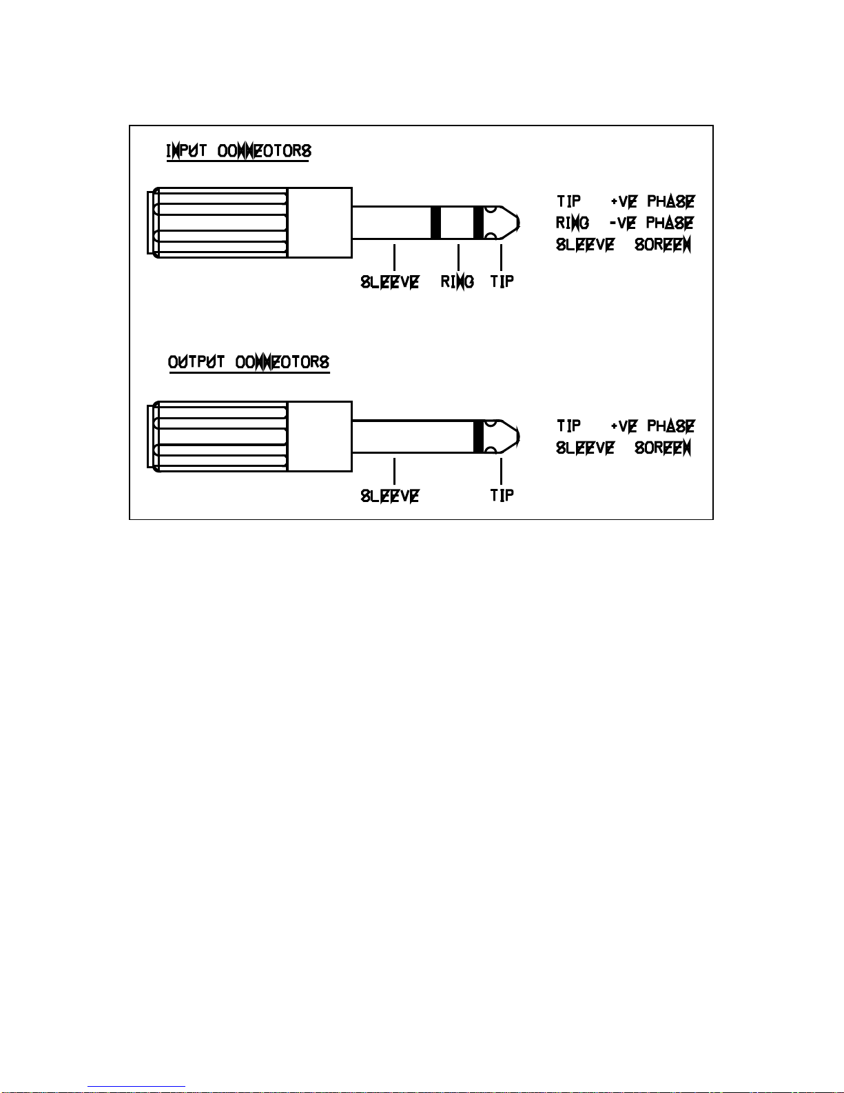
Signal Inputs
Each channel can be connected by either of
the ¼" Jack connectors. Both the jack
sockets for each channel are wired in
parallel to enable amplifier inputs to be
linkedtogetherforlargesound systems.The
inputs which are unbalanced have a 3 pole
jack socket for compatibility with balanced
systems. They should be wired as follows:
Tip Positive phase
Ring Negative phase
Sleeve Screen
For balanced inputs the screen and negative
phase will be connected together if a 3 pole
jack plug is used or theinput canbe wired to
a2 pole jack plug with the positive phase to
the tip and the negativephaseand the screen
connected to the sleeve. DO NOT leave
either of the negative or positive phase
inputs unconnected as this will result in a
reduced output level and increased noise.