SoundPals ADLY-4A User manual
SoundPals™
ADLY-4A User Guide
Four channel AES3 Delay

Printing History
SoundPals
™
ADLY-4/A AES3 Audio Delay
Rev. N/C
JANUARY 2015
Printed in U.S.A.
Part Number 08-2055-00
The information contained in this guide is subject to change without notice or obligation.
Copyrights and Trademarks
© 2015
Contents of this publication may not be reproduced in any form without the written permission of RJM & Associates.
Reproduction or reverse engineering of copyrighted software is prohibited.
FCC Compliance
This equipment has been tested and found to comply with the limits for a Class A digital device pursuant to Part 15
of the FCC Rules. These limits are designed to provide reasonable protection against harmful interference when the
equipment is operated in a commercial environment. This equipment generates, uses, and can radiate radio
frequency energy and, if not installed and used in accordance with the instruction manual, may cause harmful
interference to radio communications. Operation of this equipment in a residential area is likely to cause harmful
interference in which case the user will be required to correct the interference at your own expense.
Warranty Statement
RJM & Associates, LLC warrants that the equipment it manufactures is free from defects in workmanship and
materials and meets applicable published specifications. Equipment that has been operated within published ratings
and has not been subjected to abuse or modification, and which fails because of such defects, will be replaced or
repaired at the Company’s discretion if it is returned, freight prepaid, to RJM within three years of receipt.
This warranty supersedes all other Warranties, express or implied. RJM & Associates is not liable for any
consequential damages.
Company Address
RJM & Associates, LLC
175 Joerschke Drive
Suite A
Grass Valley, CA 95945
530-205-3437

Table of Contents
ii • Table of Contents ADLY-4/A User Guide
Table of Contents ii
Introduction 1
What are SoundPals?.............................................................................................................. 1
Documentation Conventions.................................................................................................... 1
Signals and Values .................................................................................................................. 1
Warnings.................................................................................................................................. 1
Unpacking and Inspection .......................................................................................................2
Power Supply Note .................................................................................................................. 2
ADLY-4/A 3
About the ADLY-4/A ................................................................................................................ 3
ADLY-4/A Installation............................................................................................................... 5
Connecting Power ............................................................................................................. 5
Connecting Inputs ............................................................................................................. 5
Connecting Outputs........................................................................................................... 5
ADLY-4/A Operation and Application ...................................................................................... 6
ADLY-4/A Interconnection ....................................................................................................... 7
Basic Digital Distribution ................................................................................................... 7
Multiple Outputs ................................................................................................................ 8
ADLY-4/A Internal Jumpers ..................................................................................................... 9
ADLY-4/A Troubleshooting ...................................................................................................... 9
ADLY-4/A Specifications........................................................................................................ 10
Audio Specifications ........................................................................................................ 10
Environmental Specifications and Dimensions ............................................................... 11
Inside the Module ........................................................................................... 11
In This Section ....................................................................................................................... 11
Before You Begin...................................................................................................................11
Opening the Module .............................................................................................................. 11
Closing the Module ................................................................................................................ 11
External Power................................................................................................ 12
About Power Supplies ........................................................................................................... 12
CE Compliance ...................................................................................................................... 12
Portable Power Sources ........................................................................................................ 12
Power Supply Specifications ................................................................................................. 12
Power Supply Sources .......................................................................................................... 13

Introduction
ADLY-4/A User Guide
Page
1
What are SoundPals?
Each RJM & Associates SoundPals module is essentially a digital audio building block that can
be used independently, or interconnected to perform more advanced mixing and audio
processing functions.
SoundPals can be used in both standalone and system configurations:
•In a “standalone” configuration, each SoundPals module is designed to perform a specific
audio processing function such as ADAT-to-Analog conversion. In this way, each module
functions as a perfect low-cost adjunct to larger mixing consoles (such as the Graham-
Patten D/ESAM series) — for single-purpose processing tasks.
•In a “system” configuration, SoundPals can be linked to form more comprehensive digital
audio tools. For field recording, studio applications, and workstation applications,
SoundPals can be used to seamlessly perform functions that would otherwise require
extensive peripheral gear. Best of all, SoundPals “systems” can be re-configured quickly
and easily — to suit your changing audio production requirements.
All SoundPals modules are extremely compact, rugged, and identical in size for ease of
installation, interconnection, and use. In addition, SoundPals support AES3id. This allows
longer, more robust AES signal distribution using standard coaxial cable. Error free distances of
1000 feet can be attained using inexpensive coaxial cables.
Documentation Conventions
The following documentation conventions are used in this guide:
•Buttons, knobs, connectors, and switches are indicated in bold-faced capital letters. For
example:
Adjust the left GAIN TRIM to …
•Primary sections are listed in bold text, with a line above:
Primary Section
•Secondary sections are listed in bold text, with no line:
Secondary Section
Signals and Values
Note the following important information regarding audio signal level:
•AES3 = Balanced output with 2 channels of digital audio (left and right)
•AES3id = Unbalanced output with 2 channels of digital audio (left and right)
Warnings
Please observe the following important warnings:
•Heed all warnings on the unit and in the instructions.
•Do not use this product in or near water.
•Route power cords and other cables so that they are not likely to be damaged.
Disconnect power before cleaning. Do not use liquid or aerosol cleaners; use only a
damp cloth.

ADLY-4/A User Guide
Page
2
Unpacking and Inspection
When you receive your SoundPals modules, inspect the cartons for signs of damage. Contact
your dealer and the shipper immediately if you suspect any damage has occurred during
shipping. Check the contents of each box to be sure that all parts are included. If any items are
missing, contact your dealer immediately.
Power Supply Note
SoundPals are delivered with a power connector only. A separate power supply must be
obtained. RJM & Associates offers several power solutions for both domestic and international
customers. Refer to “External Power” for detailed power specifications for users who wish to
configure their own power source, rather than purchase one from RJM.

ADLY-4/A
ADLY-4/A User Guide
Page
3
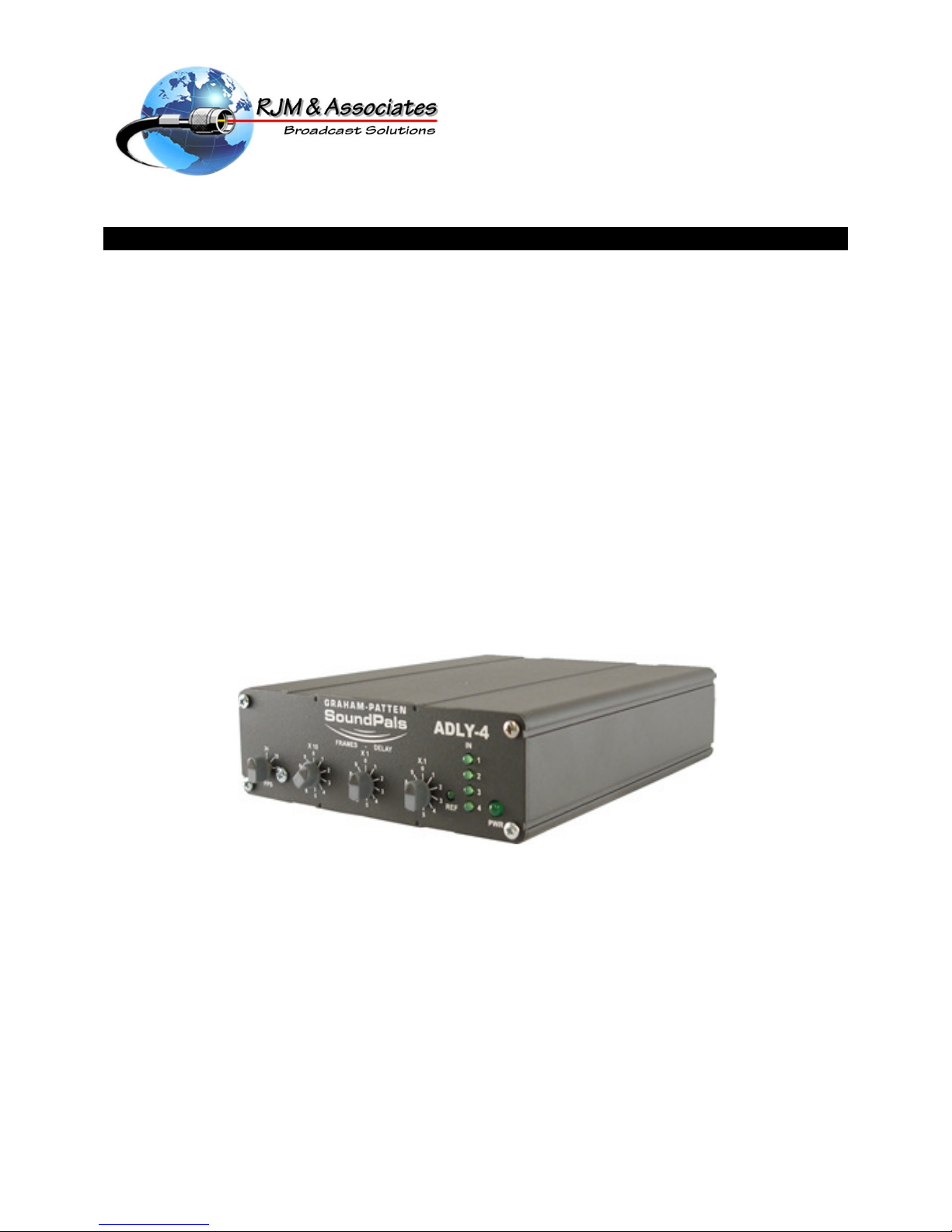
About the ADLY-4/A
The RJM & Associates SoundPals ADLY-4/A is an 8 channel (4 AES pairs) audio delay solution
which ties the audio delay to video frame delay values. The ADLY-4/A delays all 8 channels up to
99.9 video frames at 24, 25 or 30 frames per second and is adjustable in 0.1 frame steps using
three decade switches. It also has a reference switch selectable to either the external AES3id
loop-thru reference BNC’s or the AES channel 1 Input. There are four valid AES input led’s as
well as a valid reference led. The unit will accept any sample rate between 32kHz and 50kHz.
The unit offers the following features:
•Four AES (8 channels) balanced inputs
•Four AES (8 channels) balanced outputs
•10-position rotary 0.1 frame delay switch
•10-position rotary 1.0 frame delay switch
•10-position rotary 10.0 frame delay switch
•Frame rate selection switch
•External AES3id reference loop thru BNC’s
•Valid AES indicator led’s (4 each)
•Valid reference led
•Data Resolution: 24 Bits
•All Channel Status and User Bits pass through at same delay as audio
•Optional rack mounting tray (1 RU)
•Optional rack mounted (1RU) XLR Input/Output Panel (8 AES pairs each)
•Compact size, rugged construction
Note that the ADLY-4/A can synchronize to any sample rate between 32kHz and 50kHz, but is only
video frame accurate at 48kHz.
The figure below illustrates the ADLY-4/A’s front panel:
2
ADLY- 4
1
REF
FRAMES - DELAY
543 67
PWR
1
2
3
4
6
0
5
7
8
9
X.1
X1
1
2
3
4
6
0
5
7
8
9
1
2
3
4
6
0
5
7
8
9
X10
2
3
4
24
25
30
1
IN
FPS
1) Video Frame Rate Switch — selects the video frame rate in frames per second.
2) X10 Frame Delay Switch — the 10-position rotary X10 Frame Delay Switch allows you to
select frame delay in multiples of 10 frames per step. (Note: frame rate is only accurate at
48kHz sample rate.)
ADLY-4/A User Guide
Page
4
3) X1 Frame Delay Switch — the 10-position rotary X1 Frame Delay Switch allows you to
select frame delay in multiples of 1 frame per step. (Note: frame rate is only accurate at
48kHz sample rate.)
4) X.1 Frame Delay Switch — the 10-position rotary X.1 Frame Delay Switch allows you
to select frame delay in multiples of 0.1 (10
th
of a frame) frames per step. (Note: frame
rate is only accurate at 48kHz sample rate.)
5) Reference LED — when lit this green led indicates a valid AES reference either using
the external reference BNC’s or AES input channel 1 depending on the selection of the
Reference Switch on the rear of the unit.
6) Valid AES Input led’s — these four green led’s indicate you have a valid AES input for
each of the led’s that is illuminated.
7) PWR — the green Power LED lights when power is applied.
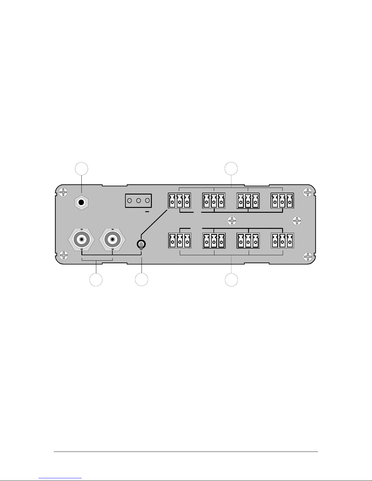
The figure below illustrates the ADLY-4/A’s rear panel:
PWR
G+
REF.
In
123 4
Out
12
35
4
1) Power Connector — accepts the power jack from the 6 VDC supply. Refer to “External
Power” for more information on external power.
2) AES Balanced Inputs — provides 4 AES balanced channel inputs via a 3 pin Phoenix
connector for each AES input channel.
3) External Reference AES3id Loop Thru BNC’s — provides a BNC external input
AES3id reference signal input, which can be looped thru, when the Reference Selection
Switch is in the down position. Note that when not using these BNC’s as a loop-thru, the
open BNC should be terminated with 75 Ohms.*
4) Reference Selection Switch — in the down position selects the AES reference from the
External AES3id Reference BNC’s. In the up position selects AES input channel 1 as the
reference.*
5) AES Balanced Outputs — provides 4 AES balanced channel outputs via a 3 pin
Phoenix connector, one for each AES output channel.
* The AES reference signal, either external or AES channel 1, must have a sampling
frequency between 30kHz and 50kHz.

ADLY-4/A User Guide
Page
5
Installation
This section provides instructions for connecting power, the reference input, and the AES
waveform inputs and outputs.
Connecting Power
Plug a 6 VDC power supply (rated at 150 mA or greater) into the appropriate voltage outlet for
your specific country, and connect the end of the cord into the jack marked PWR. Secure the
locking ring finger tight. The green PWR LED lights when power is applied.
Connecting Reference Input
The ADLY-4/A can be synchronized to an external AES3id signal waveform or can be set to
synchronize to the AES channel 1 input based on the position of the Reference Selection
Switch.
With the Reference Selection Switch in the down position the internal sample rate is locked to
and set by the AES3id signal present on the External Reference AES3id loop-thru BNC’s.
These BNC inputs accept any valid AES3id 75 ohm signal with a sample rate between 30-50 kHz
and a voltage level between 400 mV and 1 volt peak-peak. Either BNC can be used as
input/output. When a valid AES3id signal is present on the BNC’s and Reference Selection
Switch is in the down position, the green Reference LED will light on the front of the unit. If the
External Reference BNC’s are not to be used as a loop-thru, the remaining BNC should be
terminated with 75 ohms. Note that when it is necessary to loop the reference to several
SoundPals, the signal must be terminated only once, and always at the last unit in the chain.
With the Reference Selection Switch in the up position the internal sample rate is locked to and
set by the AES signal present on the AES Channel 1 input. This input will accept any valid
balanced AES 110 ohm signal with a sample rate between 30-50 kHz and a voltage level
between with 2-8 volts peak-peak. When a valid AES3 signal is present on input channel 1’s 3 pin
Phoenix connector and the Reference Selection Switch is in the up position, the green
Reference LED will light on the front of the unit. See “Connecting the AES waveform inputs” for
information on wiring this input.
Connecting the AES Waveform Inputs
There are four AES input channel pairs (8 channels of audio) available on the rear of the unit via
four male 3 pin Phoenix connectors. Cabling for the balanced inputs is as follows: Pin 1 is the
+ lead, Pin 2 is ground and Pin 3 is the –lead. A silkscreen of these connections is clearly
visible next to these connectors on the rear of the unit. Note all four AES input pairs must be
frequency locked at the same sample rate.
Connecting the AES Waveform Outputs
There are four AES output channel pairs (8 channels of audio) available on the rear of the unit via
four male 3 pin Phoenix connectors. Cabling for the balanced outputs is as follows: Pin 1 is the
+ lead, Pin 2 is ground and Pin 3 is the –lead. A silkscreen of these connections is clearly
visible next to these connectors on the rear of the unit. All four AES output pairs will be locked to
the selected reference and will be delayed by the same amount set by the three rotary frame
delay switches.
ADLY-4/A User Guide
Page
6
Operation
This section provides explanations of the rotary frame delay and Ref switches on the front panel
of the ADLY-4/A.
Using the Video Frame Rate Switch
The 3-position Video Frame Rate Switch allows a selection of the delay based on frame rates of
24, 25 and 30 frames per second. Select the frame rate of the video to be delayed by rotating the
switch. It should be noted that the video frame rates are only accurate at a 48kHz sample rate
reference. At other sample rates the delay time is 48kHz divided by the sample rate. As an
example, if the sample is 32kHz, the delay is 48kHz/32kHz or 1.5 times the selected delay.
24
25
30
FPS
Frame Rate Switch
The table below provides delay values in milli-seconds for each Frame Delay Switch based on
where the Video Frame Rate Switch is set. Note that these values are based on a 48kHz
sample rate.
Position 10 Frames @ 48kHz 1 Frame @ 48kHz 0.1 Frames @ 48kHz
24 416.4 ms 41.6 ms 4.16 ms
25 400 ms 40 ms 4.0 ms
30 333.33 ms 33.33 ms 3.33 ms
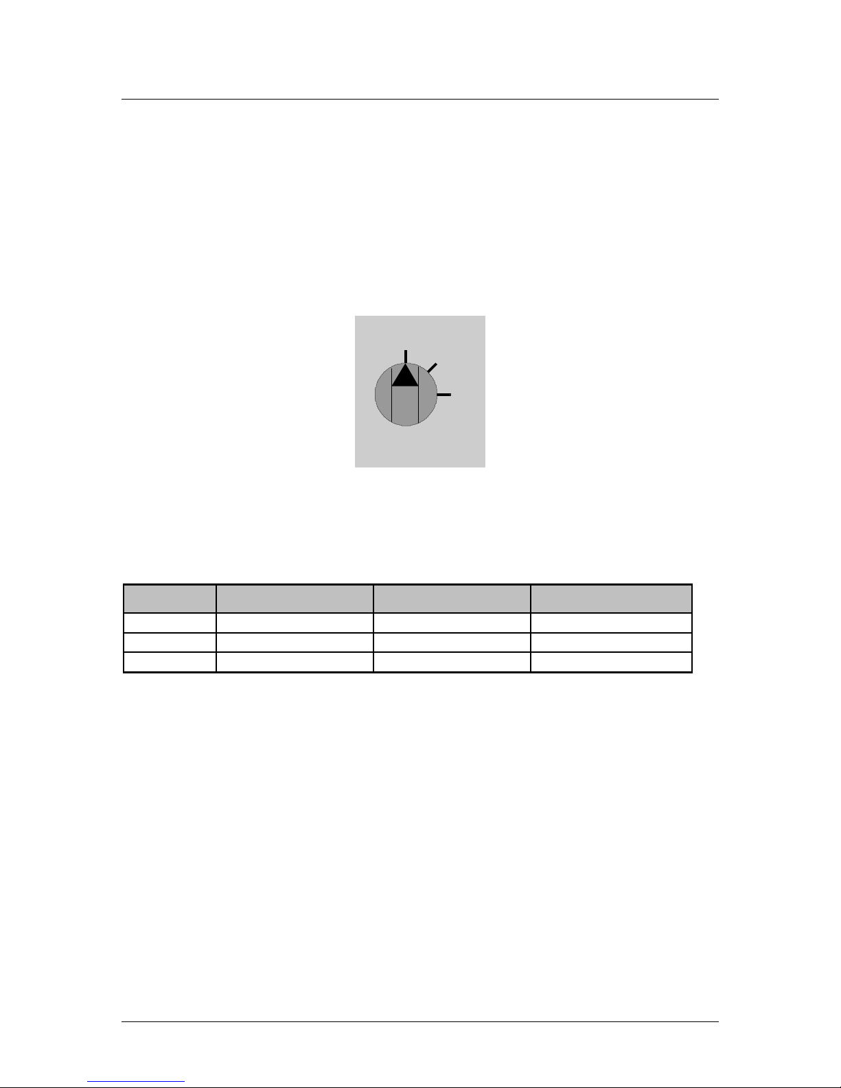
Using the Frame Delay Switches
The three 10-position Frame Delay Switches are divided into three separate values. These
values are X10, X1 and X.1 and are labeled above the switch that they apply to. Dial in the delay
in frames desired using the multiplier labeled above the switch. The illustration below shows a
delay of 74.2 frames. The X10 switch is set to 7 which represents 70 frames, the X1 switch is set
to 4 which represents 4 frames and the X.1 switch is set to 2 which represents .2 frames. Adding
them together makes the 74.2 frames of delay. At a 48kHz audio sample rate and 30 frames per
second video setting this is a total delay of 2.47098 seconds. All four balanced AES outputs will
be delayed by this value.

ADLY-4/A User Guide
Page
7
1
2
3
4
6
0
5
7
8
9
X.1
1
2
3
4
6
0
5
7
8
9
1
2
3
4
6
0
5
7
8
9
X10 X1
FRAMES - DELAY
Using the Reference Selection Switch
The 2-position Reference Selection Switch allows for selection of the ADLY-4/A internal sample
rate to lock to and be set by the Reference Input BNC’s or AES Channel 1 input. With the switch
set as shown, in the down position, the ADLY-4 uses the AES3id signal present on the reference
BNC’s.
REF.
By placing the Reference Selection Switch in the up position the ADLY-4/A internal sample rate
is locked to and set by the AES Channel 1 input present on the 3 pin male Phoenix connector
labeled In 1.
Several things about the reference signal should be noted. First, there must be a valid AES
signal present on either one of the BNC inputs or the AES Channel 1 input at a sampling
frequency of between 30-50kHz. This can be verified by insuring that the Reference LED is lit.
Secondly, the Frame Delay values set by the Frame Delay Switches are only accurate at a
48kHz sample rate signal. Third, the AES reference signal used should be phase lock looped to
the video using a VRG-1 (SoundPal Video Reference Generator) for accuracy.

ADLY-4/A User Guide
Page
8
Interconnection
This section demonstrates a typical ADLY-4/A interconnection diagram.
•De-embedding and Delaying Embedded Audio
In this application, a house NTSC reference is connected to the VRG-1 SoundPal to
create an AES3id reference signal that is locked to the house NTSC signal. This AES3id
signal is then routed to the External Reference AES3id BNC input on the ADLY-4/A. Its
loop-thru output is then terminated. The Reference Selection Switch is set to the down
position to lock the ADLY-4/A to the external BNC AES3id input and the FPS is then set
to 30 frames to be frame accurate to the NTSC signal. A synchronous HDTV signal with
the embedded audio that is to be delayed is then fed to an AEDM-4/HD SoundPal. This
SoundPal de-embeds any two of the four channel groupings into 8 channels (four AES3
channel pairs) of synchronous audio. This audio is then fed to the ADLY-4/A SoundPal
Delay module. The output of the ADLY-4/A Delay module then provides the 8 Channels
(4 AES3 Channel Pairs) of audio delayed by the amount of frames set by the three
Delay-Frame Switches and locked to the house NTSC reference.
AES3id
Loop Thru
AES3
Inputs
8 Channels
Delay-Frame
Switches
X.1
SoundPals
ADLY-4/A
X1
X10
FPS
Switch
AES3
Outputs
8 Channels
Group
AB
H e a d p h o n e
V ol u m e
SoundPals
AEDM-4/HD
AES3
Outputs
8 Channels
HD Video
Out
HD Video
In
Delayed
AES3 Audio
To Destination
Termination
Synchronous
HDTV Signal with
Embedded Audio
Mode
Switch
PWR
Word Clock Out
AES Out
AES3ID Out
Video In
Loop
Termination
SoundPals
VRG-1
NTSC House Reference
Note: It is possible in this setup to lock the ADLY-4/A to the Channel 1 input by placing
the Reference Selection Switch to the up position, therefore eliminating the VRG-1. If the
Channel 1 AES3 Data stream is consistent this will work just fine. If not, for stability
reasons, it is suggested that an external AES3id sync be used to insure that the AES3
input receivers remained locked even with the loss of the AES3 data stream.

ADLY-4/A User Guide
Page
9
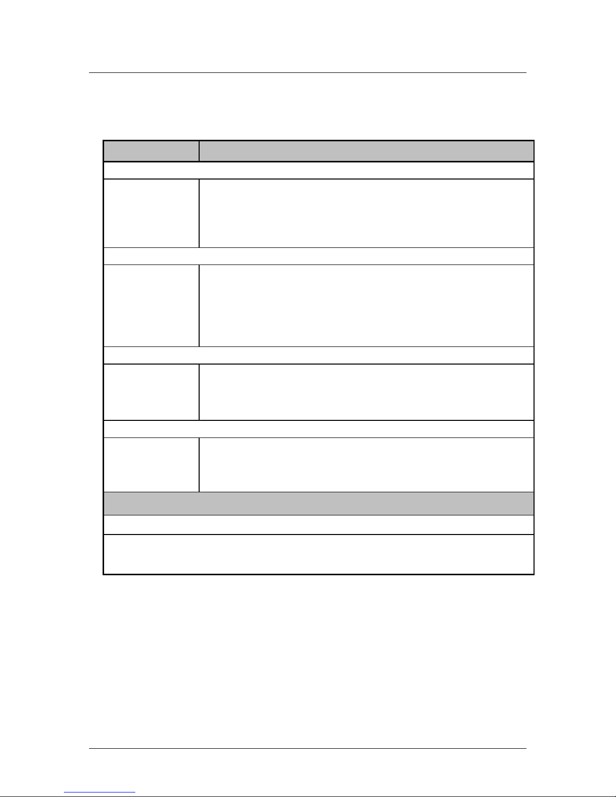
Troubleshooting
The table below lists several ADLY-4/A problems, and provides a variety of “checklist” procedures
designed to solve them.
Problem Procedure
Power LED does not
light, no outputs.
•
Ensure wall supply is plugged in properly and power connection is tight, not
loose.
•
Check voltage from wall power supply for minimum 6 volts DC. Measure
voltage at the supply connector, when disconnected from the ADLY-4/A.
REF LED does not
light with an AES3id
input connected to
the REF input
BNC’s.
•
Check that the Reference Select Switch is in the down position.
•
Ensure that the amplitude of the AES3id signal is between .4 and 1.2 volts
p-p, when connected to the ADLY-4/A REF Input BNC’s.
•
Ensure that sample rate of the reference input is not outside the 30-50kHz
range.
REF LED does not
light with an AES3
input connected to
the Channel 1 Input.
•
Check that the Valid AES Input 1 LED is lit.
•
Check that the Reference Select Switch is in the up position.
Input Valid LED’s
won’t light.
•
Ensure that the amplitude of the AES3 signal is between 2 and 8 volts p-p,
differentially when connected to the ADLY-4/A.
•
Ensure that sample rate of the input is not outside the 30-50kHz range.
Clicking sound in
audio tones.
•
Check that the REF LED is on.
•
Check that the devices that are feeding the ADLY-4/A inputs are also
locked to the same source as the ADLY-4/A reference.
NOTE
Please contact the RJM factory if the problem still exists after completing the above
procedures.
ADLY-4/A User Guide
Page
10
Specifications
This section provides ADLY-4/A audio and environmental specifications.
Audio Specifications
Parameter Specification
AES3 Inputs
Nominal amplitude 2-8 Volts Peak-Peak
Sample Rate 30-50kHz
Input impedance 110 Ω±20% (0.1–6 MHz)
Input Word Length Up to 24 bits
AES3 Outputs
Nominal amplitude 3.5 Volts Peak-Peak
Sample Rate 30-50kHz
Rise time 15-30 ns
Output impedance 110 Ω
Output Word Length Up to 24 Bits (same as input word length)
Status Bits All status bits are passed through unchanged
AES3ID Reference Input
Min. eye opening 165 mV x 0.5UI (typical level 1 V p-p)
Input impedance 75
Ω
Sample frequency 30-50kHz
Internal Delay through Unit
All Switches set to 0 166uS ± 20uS
Options
RT-2, 1RU rack tray for mounting up to 3 units
Power supplies:
•
PSU-1, 90-260V 50/60Hz in-line power supply with detachable IEC power cord
NOTE
All specifications listed above subject to change without notice.

ADLY-4/A User Guide
Page
11
Environmental Specifications and Dimensions
Parameter Specification
Dimensions
(less connectors)
5.2W x 1.62H x 6.625D
13.2 x 4.1 x 16.8 cm
Power <150 mA @ 6Vdc
Operating Temp. 10 – 50
°
C
Operating
Humidity
10 – 90%RH non-condensing
Inside the Module
In This Section
There are no serviceable items inside the SoundPals ADLY-4/A module.
Before You Begin
Check the following items before opening the module and attempting to remove the internal
circuit board:
If required, remove the SoundPals module from the rack tray.
Disconnect the power supply from the front of the product.
Disconnect all input and output cables.
Perform the remaining steps only in a static free environment. Make sure that you and
the product are both grounded.
The following tools are required:
•#2 Philips screwdriver
Opening the Module
Use the following steps to open the ADLY-4/A module:
1. On the front panel, remove the four knobs from the Frame-Delay and FPS Switches.
2. On the front panel, remove the four Phillips screws from the four corners of the
SoundPals module using the #2 Phillips screwdriver.
3. On the front panel, remove the one Phillips circuit board mounting screw.
4. On the rear panel, remove the four Phillips screws from the four corners of the
SoundPals module using the #2 Phillips screwdriver.
5. Pulling the rear panel, carefully draw the internal circuit board and front panel assembly
from the housing.
6. Set the housing and all mounting hardware in a safe place.
Closing The Module
Use the following steps to close a SoundPals module:
1. Ensure that the product label is on the bottom.
2. Carefully slide the internal circuit board and rear panel assembly through the housing.
3. Start all five screws on the front panel.
ADLY-4/A User Guide
Page
12
4. Tighten all four screws on the corners of the rear panel followed by tightening all four
screws on the corners of the front panel.
5. Snug up the last screw next to the FPS switch on the front panel.
CAUTION
Do not over tighten this screw.
7. Replace the four knobs removed earlier from the Frame-Delay and FPS Switches on the
front panel.
External Power
About Power Supplies
An external power supply conforming to the specifications listed in the following “Power Supply
Specifications” section must be used to guarantee that published SoundPals performance
figures are met. Any power supply meeting these specifications will supply adequate power for a
single SoundPals module. Although the specification is written for power supplies running from
AC line inputs, DC (battery) sources may be used if they meet all of the listed requirements.
CE Compliance
For CE compliance, the power supply that you use must comply with the following requirements:
•Low Voltage Directive 73/23/EEC
•EMC Directive 89/336/EEC
•EMC Directive 93/68/EEC
•The connector locking ring must be tight.
Portable Power Sources
For portable SoundPals power sources, sealed lead-acid, nickel cadmium or alkaline primary
batteries may be used. However, the maximum voltage must not exceed 8.6 volts, and a
minimum of 5.6 volts is required for normal operation. Maximum current drain will be 161 mA.
Power Supply Specifications
The following specifications must be met over all anticipated operating conditions including AC
power line range, temperature range, etc.
Parameter Specification
Output voltage 5.6V minimum (measured at trough of ripple) at 161 mA constant current.
8.6V maximum (measured at peak of ripple) at 105 mAconstant current.
Ripple voltage 2V p-p at 700 mA constant current.
400 mV p-p at 700mA constant current with external 2200
µ
F capacitor.
Connector Switchcraft 761K with center positive, sleeve negative.

ADLY-4/A User Guide
Page
13
Power Supply Sources
In addition to the RJM-supplied universal power supply, the following power supplies meet the
SoundPals requirements:
Company Model Note
Stancor STA-4860 120V AC, 60 Hz
Stancor STAF-0797F 220V AC, 50 Hz with European wall plug (CE compliant).
Elpac MI2007 95-250V AC, 47-63 Hz with IEC inlet (line cord required). Will power up to six
units (CE compliant).
Table of contents


