Soundtrack USA Titan-18P User manual

W15AL/W18XA

The symbol is used to indicate that some hazardous live terminals are involved within this apparatus, even
under the normal operating conditions, which may be sufficient to constitute the risk of electric shock or
death.
The symbol is used in the service documentation to indicate that specific component shall be replaced
only by the component specified in that documentation for safety reasons.
Protective grounding terminal
Alternating current/voltage
Hazardous live terminal
ON: Denotes the apparatus is turned on
OFF: Denotes the apparatus is turned off.
WARNING: Describes precautions that should be observed to prevent the danger of injury or death to the operator.
CAUTION: Describes precautions that should be observed to prevent danger of the apparatus.
IMPORTANT SAFETY INSTRUCTIONS
·Read these instructions.
·Keep these instructions.
·Heed all warning.
·Follow all instructions.
Water & Moisture·
The apparatus should be protected from moisture and
rain, can not used near water, for example: near bath-
tub, kitchen sink or a swimming pool, etc.
·Heat
The apparatus should be located away from the heat
source such as radiators, stoves or other appliances
that produce heat.
·Ventilation
Do not block areas of ventilation opening. Failure to
do could result in fire. Always install accordance with
the manufacturer's instructions.
·Object and Liquid Entry
Objects do not fall into and liquids are not spilled into
the inside of the apparatus for safety.
·Power Cord and Plug
Protect the power cord from being walked on or pinched
particularly at plugs, convenience receptacles, and the
point where they exit from the apparatus.
Do not defeat the safety purpose of the polarized or
grounding-type plug. A polarized plug has two blades
with one wider than the other. A grounding type plug
has two blades and a third grounding prong. The wide
blade or the third prong is provided for your safety.
If the provided plug does not fit into your outlet, refer to
electrician for replacement.
CAUTION
RISK OF ELECTRIC SHOCK
DO NOT OPEN
IMPORTANT SAFETY SYMBOLS
°
·Power Supply
The apparatus should be connected to the power supply
only of the type as marked on the apparatus or described
in the manual. Failure to do could result in damage to the
product and possibly the user.
Unplug this apparatus during lightning storms or when
unused for long periods of time.
·Fuse
To prevent the risk of fire and damaging the unit, please
use only of the recommended fuse type as described in
the manual. Before replacing the fuse, make sure the unit
turned off and disconnected from the AC outlet.
·Electrical Connection
Improper electrical wiring may invalidate the product war-
ranty.
·Cleaning
Clean only with a dry cloth. Do not use any solvents such
as benzol or alcohol.
·Servicing
Do not implement any servicing other than those means
described in the manual. Refer all servicing to qualified
service personnel only.
·Only use accessories/attachments or parts recommended
by the manufacturer.
·Warning
Please remember the high sound pressure do not only
temporarily damage your sense of hearing, but can also
cause permanent damage. Be careful to select a suitable
volume.

POWER
ON
OFF
Limit
Signal
Power
Off
On
POLARITY
IN
L L
R R
L
R
OUT
PARALLEL
PARALLEL
FULL RANGE LINE
100Hz LOW-CUT
OUT
100Hz LOW-CUT
OUT
FRO NT/L ED
AC INPUT
AC 100-120V 60Hz
T6.3A/250V
AC 200-240V 50Hz
T3.15A/250V
1 Features
The Sub woofer speakers are designed for professional stage, using high strength and density board,
for cabinet, two metal handle, enjoying strong subwoofer. Attractive appearance with black paint finishing,
containing precise crossover frequency for good performance, four rubber corners in bottom bracket and sides
to protect the unit. User can select different location for own need, Sub woofer speakers includes precise electronic
crossover, with high power woofer used with CLASS D amplifier, especially applied to conference and club.
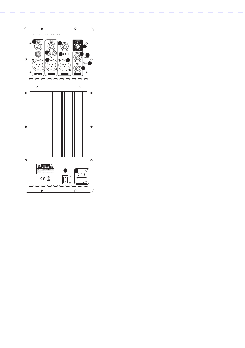
2 Control Element
W118XA
12 4
5
9
6
7
11
10
8
3
X OVER
40Hz 250Hz
GAIN
-20 +10dB
Normal
Reverse

POWER
AUX LEVEL
AUX IN
MIX OUT
LINE IN EQ
AUX IN
AC INPUT
AC110V 60Hz-T4A/250V
1
2
3
4
6
5
7
8
9
11
10
12 13
W115AL
1. MIC INPUT
Plug a mic directly into this port for public address usage and let
your voice be heard. (No phantom power)
2. RCA INPUT
Connect a CD player, digital media player, mixer, or other media
source to these inputs. Control the output volume using the Line
Input volume knob.
3. LINE INPUT(XLR)
Connect a line-level mixer or musrical instrument to this XLR
line-level input. Control the output volume using the Line Input
volume knob. Use this line-level input when linking together two
peaker units.
4. AUX VOLUME CONTROL
This knob is used to control volume of the AUX IN.
5. AUX INPUT
For 3.5" input or other mobile devices signal input.
6. MIX OUT
Connect this XLR output to another active (powered) speaker.
The level of the output is controlled by each channel’s volume
setting (Mic Input volume, Line Input volume, and Media Panel
volume)
7. MASTER VOLUME CONTROL
This control enables you to adjust the total volume level.
8. TREBLE CONTROL
This knob is used to regulate the amount treble applide to the
output signal.
9. BASS CONTROL
This knob is used to regulate the amount bass applied to the output signal.
10. Power LED
Indicates whether speaker is powered on or off.
11. CLIP LED
CLIP LED: This LED will flash red if the signal from inputs or Media Panel source is clipping. If this happens
decrease the setting of the Mic Input volume knob, Line Level volume knob, or Media Panel volume knob.
12. POWER SWITCH
This power switch turns on the system. Remember to adjust the volume level to the lowest setting before
turn on the power switch.
13. AC INPUT CONNECTOR
Connect the included power cord to the AC input connector before push on the power switch.

12"/15" 2-way 12"/15" 2-way
+4
-10
L R
0
- +15
8
2
PAN
L R
0
- +15
8
PRE
2
PAN
L R
0
- +15
8
PRE
2
PAN
L R
0
- +15
8
PRE
2
PAN
L R
0
- +15
8
PRE
2
BAL
L R
0
- +15
8
PRE
2
BAL
+10 -40
0
-15 +15
0
-15 +15
0
-
8
+15
0
-15 +15
MIC
HIGH
12 KHz
EQ
MID
2.5 KHz
LOW
80 Hz
AUX1
1
MUTE
ALT 3-4
+10 +60
TRIM
dB/dBu
LOW CUT
75Hz
18 dB/Oct
LINE IN
+10 -40
0
-15 +15
0
-15 +15
0
-
8
+15
0
-15 +15
MIC
HIGH
12 KHz
EQ
MID
2.5 KHz
LOW
80 Hz
AUX1
2
MUTE
ALT 3-4
+10 +60
TRIM
dB/dBu
LOW CUT
75Hz
18 dB/Oct
LINE IN
+10 -40
0
-15 +15
0
-15 +15
0
-
8
+15
0
-15 +15
MIC
HIGH
12 KHz
EQ
MID
2.5 KHz
LOW
80 Hz
AUX1
3
MUTE
ALT 3-4
+10 +60
TRIM
dB/dBu
LOW CUT
75Hz
18 dB/Oct
LINE IN
+10 -40
0
-15 +15
0
-15 +15
0
-
8
+15
0
-15 +15
MIC
HIGH
12 KHz
EQ
MID
2.5 KHz
LOW
80 Hz
AUX1
4
MUTE
ALT 3-4
+10 +60
TRIM
dB/dBu
LOW CUT
75Hz
18 dB/Oct
LINE IN
0
-15 +15
0
-15 +15
0
-
8
+15
0
-15 +15
HIGH
12 KHz
EQ
MID
2.5 KHz
LOW
80 Hz
AUX1
5/6
MUTE
ALT 3-4
0
-15 +15
0
-15 +15
0
-
8
+15
0
-15 +15
HIGH
12 KHz
EQ
MID
2.5 KHz
LOW
80 Hz
AUX1
7/8
MUTE
ALT 3-4
0
15
8
0
15
8
1
2
0
8
0
8
1
2
0
8
1
STEREO AUX RETURNS
MAIN MIX
ALT 3-4
PROGRAM
(PUSH)
BAL
OR
UNBAL
BAL
OR
UNBAL
BAL
OR
UNBAL
BAL
OR
UNBAL
LEFT/MONO RIGHT
1
2
1
2
FX
AUX SENDSRETURNSSTEREO AUX
MONO
BAL
OR
UNBAL
L
R
LEVEL
LINE IN 5/6
4LINE IN 7/8
+4
-10
MONO
L
R
LEVEL
321 PHONES
FX
FOOTSW
IN OUT
2-TRACK IN/OUT
L
R
L
R
BAL
OR
UNBAL
1
TO AUX
SEND 1
88
8
FX FX
AUX SENDS
FX FX FX FX FX FX
ALT 3-4 MAIN MIX
24-BIT MULTI-FX PROCESSOR
HIGH QUALITY 14 INPUT 2/2 BUS MIXER
24-BIT DSP FX PROCESSOR
2 3 4 5/6 7/8
00 SMALL HALL
03 MID HALL
06 BIG HALL
09 CHURCH
10 SMALL ROOM
13 MID ROOM
16 BIG ROOM
19 CHAPEL
20 PLATE
27 SPRING
30 GATED REV
36 REVERSE
40 EARLY REFL
44 AMBIENCE
48 STADIUM
49 AMBIENCE FX
50 DELAY
59 ECHO
60 CHORUS
66 FLANGER
70 PHASER
74 PITCH SHIFT
80 CHORUS & REVERB
82 FLANGER & REVERB
84 PHASER & REVERB
86 PITCH & REVERB
88 DELAY & REVERB
90 DELAY & GATED
91 DELAY & REVERSE
92 DELAY & CHORUS
94 DELAY & FLANGER
96 DELAY & PHASER
98 DELAY & PITCH
- +15
8
3 4
10
0
10
15
20
25
30
40
60
8
dB
10
MUTE
CLIP
0
10
15
20
25
30
40
60
8
dB
10
MUTE
CLIP
0
10
15
20
25
30
40
60
8
dB
10
MUTE
CLIP
0
10
15
20
25
30
40
60
8
dB
10
MUTE
CLIP
0
10
15
20
25
30
40
60
8
dB
10
MUTE
CLIP
0
10
15
20
25
30
40
60
8
dB
10
MUTE
CLIP
0
10
15
20
25
30
40
60
8
10
0
10
15
20
25
30
40
60
8
10
0
10
15
20
25
30
40
60
8
10
0
10
15
20
25
30
40
60
8
MODE
SOLO (NORMAL)
PFL (LEVEL SET)
L R
MAIN SOLO PFL
MAIN MIX
ALT 3-4
2-TRACK
PHONES/CTRL R
SOURCE
2TK TO MAIN MIX
POWER +48 V
CLIP
10
5
2
0
2
5
20
SOLO SOLO SOLO SOLO SOLO SOLO
POST
PRE
POST
PRE
POST
PRE
POST
PRE
POST
PRE
POST
PRE
SOLO
SOLO
CLIP
-
3
-
6
-
10
-
15
-
20
24-BIT DUAL ENGINE DSP
LEVEL
24-BIT A/D & D/A CONVERTER
+4
-10
L R
0
- +15
8
2
PAN
L R
0
- +15
8
PRE
2
PAN
L R
0
- +15
8
PRE
2
PAN
L R
0
- +15
8
PRE
2
PAN
L R
0
- +15
8
PRE
2
BAL
L R
0
- +15
8
PRE
2
BAL
+10 -40
0
-15 +15
0
-15 +15
0
-
8
+15
0
-15 +15
MIC
HIGH
12 KHz
EQ
MID
2.5 KHz
LOW
80 Hz
AUX1
1
MUTE
ALT 3-4
+10 +60
TRIM
dB/dBu
LOW CUT
75Hz
18 dB/Oct
LINE IN
+10 -40
0
-15 +15
0
-15 +15
0
-
8
+15
0
-15 +15
MIC
HIGH
12 KHz
EQ
MID
2.5 KHz
LOW
80 Hz
AUX1
2
MUTE
ALT 3-4
+10 +60
TRIM
dB/dBu
LOW CUT
75Hz
18 dB/Oct
LINE IN
+10 -40
0
-15 +15
0
-15 +15
0
-
8
+15
0
-15 +15
MIC
HIGH
12 KHz
EQ
MID
2.5 KHz
LOW
80 Hz
AUX1
3
MUTE
ALT 3-4
+10 +60
TRIM
dB/dBu
LOW CUT
75Hz
18 dB/Oct
LINE IN
+10 -40
0
-15 +15
0
-15 +15
0
-
8
+15
0
-15 +15
MIC
HIGH
12 KHz
EQ
MID
2.5 KHz
LOW
80 Hz
AUX1
4
MUTE
ALT 3-4
+10 +60
TRIM
dB/dBu
LOW CUT
75Hz
18 dB/Oct
LINE IN
0
-15 +15
0
-15 +15
0
-
8
+15
0
-15 +15
HIGH
12 KHz
EQ
MID
2.5 KHz
LOW
80 Hz
AUX1
5/6
MUTE
ALT 3-4
0
-15 +15
0
-15 +15
0
-
8
+15
0
-15 +15
HIGH
12 KHz
EQ
MID
2.5 KHz
LOW
80 Hz
AUX1
7/8
MUTE
ALT 3-4
0
15
8
0
15
8
1
2
0
8
0
8
1
2
0
8
1
STEREO AUX RETURNS
MAIN MIX
ALT 3-4
PROGRAM
(PUSH)
BAL
OR
UNBAL
BAL
OR
UNBAL
BAL
OR
UNBAL
BAL
OR
UNBAL
LEFT/MONO RIGHT
1
2
1
2
FX
AUX SENDSRETURNSSTEREO AUX
MONO
BAL
OR
UNBAL
L
R
LEVEL
LINE IN 5/6
4LINE IN 7/8
+4
-10
MONO
L
R
LEVEL
321 PHONES
FX
FOOTSW
IN OUT
2-TRACK IN/OUT
L
R
L
R
BAL
OR
UNBAL
1
TO AUX
SEND 1
88
8
FX FX
AUX SENDS
FX FX FX FX FX FX
ALT 3-4 MAIN MIX
24-BIT MULTI-FX PROCESSOR
HIGH QUALITY 14 INPUT 2/2 BUS MIXER
24-BIT DSP FX PROCESSOR
2 3 4 5/6 7/8
00 SMALL HALL
03 MID HALL
06 BIG HALL
09 CHURCH
10 SMALL ROOM
13 MID ROOM
16 BIG ROOM
19 CHAPEL
20 PLATE
27 SPRING
30 GATED REV
36 REVERSE
40 EARLY REFL
44 AMBIENCE
48 STADIUM
49 AMBIENCE FX
50 DELAY
59 ECHO
60 CHORUS
66 FLANGER
70 PHASER
74 PITCH SHIFT
80 CHORUS & REVERB
82 FLANGER & REVERB
84 PHASER & REVERB
86 PITCH & REVERB
88 DELAY & REVERB
90 DELAY & GATED
91 DELAY & REVERSE
92 DELAY & CHORUS
94 DELAY & FLANGER
96 DELAY & PHASER
98 DELAY & PITCH
- +15
8
3 4
10
0
10
15
20
25
30
40
60
8
dB
10
MUTE
CLIP
0
10
15
20
25
30
40
60
8
dB
10
MUTE
CLIP
0
10
15
20
25
30
40
60
8
dB
10
MUTE
CLIP
0
10
15
20
25
30
40
60
8
dB
10
MUTE
CLIP
0
10
15
20
25
30
40
60
8
dB
10
MUTE
CLIP
0
10
15
20
25
30
40
60
8
dB
10
MUTE
CLIP
0
10
15
20
25
30
40
60
8
10
0
10
15
20
25
30
40
60
8
10
0
10
15
20
25
30
40
60
8
10
0
10
15
20
25
30
40
60
8
MODE
SOLO (NORMAL)
PFL (LEVEL SET)
L R
MAIN SOLO PFL
MAIN MIX
ALT 3-4
2-TRACK
PHONES/CTRL R
SOURCE
2TK TO MAIN MIX
POWER +48 V
CLIP
10
5
2
0
2
5
20
SOLO SOLO SOLO SOLO SOLO SOLO
POST
PRE
POST
PRE
POST
PRE
POST
PRE
POST
PRE
POST
PRE
SOLO
SOLO
CLIP
-
3
-
6
-
10
-
15
-
20
24-BIT DUAL ENGINE DSP
LEVEL
24-BIT A/D & D/A CONVERTER
Application Examples #1
This example shows a two-channel (stereo) setup utilizing one subwoofer and two top-boxes.
Audio signals for the left and right channels are supplied by the mixer console. this signal source can be just about any
variable-output level audio source, such as DJ mixers, professional CD players, or computer-based audio signal sources.
Audio output from the mixer is connected to the subwoofer left (L) and right (R) channels. The subwoofer's R and L FULL
RANGE LINE OUT connectors are used to connect to its respective top-box. Turn ON each top-box's 100 Hz LOW-CUT
FILTER.
Alternately, the top-boxes could be connected to the subwoofer's 100 Hz LOW-CUT OUT and the top-boxes 100 Hz LOW-
CUT OUT FILTER turned off. The only possible issue with this method of connection is unexpected noises (turn-off thumps)
if the subwoofer is powered up or down while the top boxes are on. If connected as shown, power sequencing is not an issue.
Channel 1 or Left channel Channel 2 or Right channel
Mixer or Other Audio Source
18" SUB Woofer
18" SUB Woofer

Channel 1 or Left channel Channel 2 or Right channel
Application Examples #2
This example shows a two-channel (stereo) setup utilizing two subwoofers and two top-boxes.
Audio signals for the left and right channels are supplied by the mixer console. this signal source can be just about any
variable-output level audio source, such as DJ mixers, professional CD players, or computer-based audio signal sources.
Audio output from the mixer is connected to the subwoofer input of each channel. Each subwoofer's FULL RANGE LINE
OUT connector is used to connect to its respective top-box. Turn ON the top-box's 100 Hz LOW-CUT FILTER.
Alternately, the top-boxes could be connected to the subwoofer's 100 Hz LOW-CUT OUT and the top-boxes 100 Hz LOW-
CUT OUT FILTER turned off. The only possible issue with this method of connection is unexpected noises (turn-off thumps)
if the subwoofer is powered down before the top-boxes. If connected as shown, power sequencing is not an issue.
18" SUB Woofer
12"/15" 2-way 12"/15" 2-way
+4
-10
L R
0
- +15
8
2
PAN
L R
0
- +15
8
PRE
2
PAN
L R
0
- +15
8
PRE
2
PAN
L R
0
- +15
8
PRE
2
PAN
L R
0
- +15
8
PRE
2
BAL
L R
0
- +15
8
PRE
2
BAL
+10 -40
0
-15 +15
0
-15 +15
0
-
8
+15
0
-15 +15
MIC
HIGH
12 KHz
EQ
MID
2.5 KHz
LOW
80 Hz
AUX1
1
MUTE
ALT 3-4
+10 +60
TRIM
dB/dBu
LOW CUT
75Hz
18 dB/Oct
LINE IN
+10 -40
0
-15 +15
0
-15 +15
0
-
8
+15
0
-15 +15
MIC
HIGH
12 KHz
EQ
MID
2.5 KHz
LOW
80 Hz
AUX1
2
MUTE
ALT 3-4
+10 +60
TRIM
dB/dBu
LOW CUT
75Hz
18 dB/Oct
LINE IN
+10 -40
0
-15 +15
0
-15 +15
0
-
8
+15
0
-15 +15
MIC
HIGH
12 KHz
EQ
MID
2.5 KHz
LOW
80 Hz
AUX1
3
MUTE
ALT 3-4
+10 +60
TRIM
dB/dBu
LOW CUT
75Hz
18 dB/Oct
LINE IN
+10 -40
0
-15 +15
0
-15 +15
0
-
8
+15
0
-15 +15
MIC
HIGH
12 KHz
EQ
MID
2.5 KHz
LOW
80 Hz
AUX1
4
MUTE
ALT 3-4
+10 +60
TRIM
dB/dBu
LOW CUT
75Hz
18 dB/Oct
LINE IN
0
-15 +15
0
-15 +15
0
-
8
+15
0
-15 +15
HIGH
12 KHz
EQ
MID
2.5 KHz
LOW
80 Hz
AUX1
5/6
MUTE
ALT 3-4
0
-15 +15
0
-15 +15
0
-
8
+15
0
-15 +15
HIGH
12 KHz
EQ
MID
2.5 KHz
LOW
80 Hz
AUX1
7/8
MUTE
ALT 3-4
0
15
8
0
15
8
1
2
0
8
0
8
1
2
0
8
1
STEREO AUX RETURNS
MAIN MIX
ALT 3-4
PROGRAM
(PUSH)
BAL
OR
UNBAL
BAL
OR
UNBAL
BAL
OR
UNBAL
BAL
OR
UNBAL
LEFT/MONO RIGHT
1
2
1
2
FX
AUX SENDSRETURNSSTEREO AUX
MONO
BAL
OR
UNBAL
L
R
LEVEL
LINE IN 5/6
4LINE IN 7/8
+4
-10
MONO
L
R
LEVEL
321 PHONES
FX
FOOTSW
IN OUT
2-TRACK IN/OUT
L
R
L
R
BAL
OR
UNBAL
1
TO AUX
SEND 1
88
8
FX FX
AUX SENDS
FX FX FX FX FX FX
ALT 3-4 MAIN MIX
24-BIT MULTI-FX PROCESSOR
HIGH QUALITY 14 INPUT 2/2 BUS MIXER
24-BIT DSP FX PROCESSOR
2 3 4 5/6 7/8
00 SMALL HALL
03 MID HALL
06 BIG HALL
09 CHURCH
10 SMALL ROOM
13 MID ROOM
16 BIG ROOM
19 CHAPEL
20 PLATE
27 SPRING
30 GATED REV
36 REVERSE
40 EARLY REFL
44 AMBIENCE
48 STADIUM
49 AMBIENCE FX
50 DELAY
59 ECHO
60 CHORUS
66 FLANGER
70 PHASER
74 PITCH SHIFT
80 CHORUS & REVERB
82 FLANGER & REVERB
84 PHASER & REVERB
86 PITCH & REVERB
88 DELAY & REVERB
90 DELAY & GATED
91 DELAY & REVERSE
92 DELAY & CHORUS
94 DELAY & FLANGER
96 DELAY & PHASER
98 DELAY & PITCH
- +15
8
3 4
10
0
10
15
20
25
30
40
60
8
dB
10
MUTE
CLIP
0
10
15
20
25
30
40
60
8
dB
10
MUTE
CLIP
0
10
15
20
25
30
40
60
8
dB
10
MUTE
CLIP
0
10
15
20
25
30
40
60
8
dB
10
MUTE
CLIP
0
10
15
20
25
30
40
60
8
dB
10
MUTE
CLIP
0
10
15
20
25
30
40
60
8
dB
10
MUTE
CLIP
0
10
15
20
25
30
40
60
8
10
0
10
15
20
25
30
40
60
8
10
0
10
15
20
25
30
40
60
8
10
0
10
15
20
25
30
40
60
8
MODE
SOLO (NORMAL)
PFL (LEVEL SET)
L R
MAIN SOLO PFL
MAIN MIX
ALT 3-4
2-TRACK
PHONES/CTRL R
SOURCE
2TK TO MAIN MIX
POWER +48 V
CLIP
10
5
2
0
2
5
20
SOLO SOLO SOLO SOLO SOLO SOLO
POST
PRE
POST
PRE
POST
PRE
POST
PRE
POST
PRE
POST
PRE
SOLO
SOLO
CLIP
-
3
-
6
-
10
-
15
-
20
24-BIT DUAL ENGINE DSP
LEVEL
24-BIT A/D & D/A CONVERTER
+4
-10
L R
0
- +15
8
2
PAN
L R
0
- +15
8
PRE
2
PAN
L R
0
- +15
8
PRE
2
PAN
L R
0
- +15
8
PRE
2
PAN
L R
0
- +15
8
PRE
2
BAL
L R
0
- +15
8
PRE
2
BAL
+10 -40
0
-15 +15
0
-15 +15
0
-
8
+15
0
-15 +15
MIC
HIGH
12 KHz
EQ
MID
2.5 KHz
LOW
80 Hz
AUX1
1
MUTE
ALT 3-4
+10 +60
TRIM
dB/dBu
LOW CUT
75Hz
18 dB/Oct
LINE IN
+10 -40
0
-15 +15
0
-15 +15
0
-
8
+15
0
-15 +15
MIC
HIGH
12 KHz
EQ
MID
2.5 KHz
LOW
80 Hz
AUX1
2
MUTE
ALT 3-4
+10 +60
TRIM
dB/dBu
LOW CUT
75Hz
18 dB/Oct
LINE IN
+10 -40
0
-15 +15
0
-15 +15
0
-
8
+15
0
-15 +15
MIC
HIGH
12 KHz
EQ
MID
2.5 KHz
LOW
80 Hz
AUX1
3
MUTE
ALT 3-4
+10 +60
TRIM
dB/dBu
LOW CUT
75Hz
18 dB/Oct
LINE IN
+10 -40
0
-15 +15
0
-15 +15
0
-
8
+15
0
-15 +15
MIC
HIGH
12 KHz
EQ
MID
2.5 KHz
LOW
80 Hz
AUX1
4
MUTE
ALT 3-4
+10 +60
TRIM
dB/dBu
LOW CUT
75Hz
18 dB/Oct
LINE IN
0
-15 +15
0
-15 +15
0
-
8
+15
0
-15 +15
HIGH
12 KHz
EQ
MID
2.5 KHz
LOW
80 Hz
AUX1
5/6
MUTE
ALT 3-4
0
-15 +15
0
-15 +15
0
-
8
+15
0
-15 +15
HIGH
12 KHz
EQ
MID
2.5 KHz
LOW
80 Hz
AUX1
7/8
MUTE
ALT 3-4
0
15
8
0
15
8
1
2
0
8
0
8
1
2
0
8
1
STEREO AUX RETURNS
MAIN MIX
ALT 3-4
PROGRAM
(PUSH)
BAL
OR
UNBAL
BAL
OR
UNBAL
BAL
OR
UNBAL
BAL
OR
UNBAL
LEFT/MONO RIGHT
1
2
1
2
FX
AUX SENDSRETURNSSTEREO AUX
MONO
BAL
OR
UNBAL
L
R
LEVEL
LINE IN 5/6
4LINE IN 7/8
+4
-10
MONO
L
R
LEVEL
321 PHONES
FX
FOOTSW
IN OUT
2-TRACK IN/OUT
L
R
L
R
BAL
OR
UNBAL
1
TO AUX
SEND 1
88
8
FX FX
AUX SENDS
FX FX FX FX FX FX
ALT 3-4 MAIN MIX
24-BIT MULTI-FX PROCESSOR
HIGH QUALITY 14 INPUT 2/2 BUS MIXER
24-BIT DSP FX PROCESSOR
2 3 4 5/6 7/8
00 SMALL HALL
03 MID HALL
06 BIG HALL
09 CHURCH
10 SMALL ROOM
13 MID ROOM
16 BIG ROOM
19 CHAPEL
20 PLATE
27 SPRING
30 GATED REV
36 REVERSE
40 EARLY REFL
44 AMBIENCE
48 STADIUM
49AMBIENCE FX
50DELAY
59ECHO
60CHORUS
66FLANGER
70PHASER
74PITCH SHIFT
80 CHORUS & REVERB
82FLANGER & REVERB
84PHASER & REVERB
86PITCH & REVERB
88DELAY & REVERB
90DELAY & GATED
91DELAY & REVERSE
92DELAY & CHORUS
94DELAY & FLANGER
96DELAY & PHASER
98DELAY & PITCH
- +15
8
3 4
10
0
10
15
20
25
30
40
60
8
dB
10
MUTE
CLIP
0
10
15
20
25
30
40
60
8
dB
10
MUTE
CLIP
0
10
15
20
25
30
40
60
8
dB
10
MUTE
CLIP
0
10
15
20
25
30
40
60
8
dB
10
MUTE
CLIP
0
10
15
20
25
30
40
60
8
dB
10
MUTE
CLIP
0
10
15
20
25
30
40
60
8
dB
10
MUTE
CLIP
0
10
15
20
25
30
40
60
8
10
0
10
15
20
25
30
40
60
8
10
0
10
15
20
25
30
40
60
8
10
0
10
15
20
25
30
40
60
8
MODE
SOLO (NORMAL)
PFL (LEVEL SET)
L R
MAIN SOLO PFL
MAIN MIX
ALT 3-4
2-TRACK
PHONES/CTRL R
SOURCE
2TK TO MAIN MIX
POWER +48 V
CLIP
10
5
2
0
2
5
20
SOLO SOLO SOLO SOLO SOLO SOLO
POST
PRE
POST
PRE
POST
PRE
POST
PRE
POST
PRE
POST
PRE
SOLO
SOLO
CLIP
-
3
-
6
-
10
-
15
-
20
24-BIT DUAL ENGINE DSP
LEVEL
24-BIT A/D & D/A CONVERTER
18" SUB Woofer
Mixer or Other Audio Source
18" SUB Woofer 18" SUB Woofer

27kg
38 kg
525×525×760mm
2.3KHz
615×570×675 mm
123dB
-3dBV
Treble, Bass
40Hz-250Hz
Class H
+2dBV
Gain control, Limit/Clip(red led), Signal Presence(green led),
AC Power(blue led), AC Power switch
Thermal limiting, On/off muting, DC protection, Short circuit protection,
RF protection, Fn cooling
Amp Type
Input Sensitivity
Amp Power
X-over
Peak Power
Input Headroom/Clipping
Dimensions (H
Dimensions (H
W
W
D)
D)
×
×
×
×
Net Weight
Net Weight
AC 100-120V 60Hz/AC 200-240V 50Hz
THD
Input Connectors/Impedance
Protections
Crossover
Output Connectors
Protection, Agency certs.
AC Power Connector and Cordset
200W RMS
400W
<=0.1%
Over Temp; Over Load; DC Protect;
XLR 22K Bal, 11K Unbal
XLR
SPL
EQ
AMP Power
1.0" Exit-1.0" Compression Drive
500W RMS
W15AL
W18XA
Two Way
45Hz-150Hz
45Hz-20KHz
40Hz-200Hz
95dB
4ohm
125dB
Specifications
Specifications
Type
Frequency Range (-3dB)
Driver
Woofer
4. TECHNICAL SPECIFICATIONS
3. WIRING
XLR
1
2
31
2
3
1: Shield 2: Hot (+) 3: Cold (-)
Tip
Ring
Sleeve
+
-
1/4" TRS JACK
Frequency Range
Frequency Range (-10dB)
Sensitivity(1m/1w)
Maximum Peak SPL
Impedance
Transducer Description LF
15" 65mm 60OZ
18" 75mm 80OZ
This manual suits for next models
3
Table of contents


