Southern Roadcraft SRV8 User manual

Southern Roadcraft Ltd.
The Shell Garage, 37 Albion Street,
Brighton, Sussex, BN4. 4DN.
Tel . No.
Assembly
Manual
Roadster
N
SRVS
sR v8 BUILD MANUAL UPDATE FBBRIIARY 1994
Please note the following amenclments to the SR VB build manual.
Page2. We are now implementing the Jaguar Series 2 steering column as availability of
the Series I has become limited.
Page 2. The MGB master cylinder and servo can now he replaced with a Ford unit
specially assembled for Southern Roadcraft.
Page 3. It is now lnore common to use an American engine and gearbox such as the
Cheuolet 350 or Ford 302 or 351. Any small block V8 engino can be used and most
big block engines can be catered for by special request. The Rover V8 engine and
gearbox is still suitable although now less popular. Roadcraft Repower, our engine
department, can assist with all your engine enquiries. As an Edelbrock main dealer we
are able to supply all parts for uprating performance etc.
Fig. 7. The Jaguar anti roll bar keeper plate is no longer requirod. All fittings are
available in the Southern Roadcraft anti roll bar kit.
Page 9. An alurninium fuel tank is now available providing larger capacity and neater
fit. the fitting procedure is different to that laid out in the manual for the steel vercion.
Page 9. Ws now offer stainless steel panels as an alternative to aluminium. These
provide a longer lasting high polished finish.
Page 19. The original 3" side pipe system has now been replaced with a 4" stakiless
system with a four into one collector on the outside of the body.
Pagc 26. It is now possible to fit larger rear bulkhead speakers when fitting the
aluminium firel tank as special cut-outs are provided in ths tank.
Please check wirh us if you have any queries regarding updates.

THE SR VB ROADSTER
Congratulations on your decision to purchase a Southern Roadcraft SR VB
Roadster. Whichever stage of build you have purchased we trust the
following information will provide for a straightforward and trouble
free bui1d. Should you require any further assistance please feel free
to contact your nearest Southern Roadcraft dealer or the factory direct.
The foll-owing sequence of instructions provided are for your reference
and are recommended for the home builder. It is the responsibility of
the home builder to check the accuracy of these instructions whilst
assembling the car. Every effort is made by the manufacturer to provide
all necessary assembly information and accuracy of parts supplied, although
Southern Roadcraft's policy of continual improvement may mean that sections
of these instructions may be outdated by redesigned parts.
If you are unsure about any aspect of your car's construction CONSULT A
QUALIFIED MOTOR ENGINEER. On completion of your vehicle the car should
be taken to a reputable garage and thoroughty examined before any road
use. Your insurance company may also require a separate engineers report.
IrrJe recommend that you lully study the build up insl,ructions before
commencing the assembly of the car.
Please check and identlfy att parts supplied to you immediately and inform
your supplier within seven days should there by any discrepancies. If you
have purchased the kit in basic kit form you should have all the parts
listed below.
1. Chassis
2. Rear diff locator beam (I)
3. Radius rods including rose joints and lock nuts (2)
4. Door hinge (2)
5. Door hinge boxes (2)
6. Engine mounts (2)
7. Steering arms (2)
B. Track rod extenders(2)
9. Front lower shock absorber plates (2)
10. Clutch, brake and throttle pedals
11. Radiator lrame ( lower )
12. lladiul.or I'r'anre (upper)
13. Ijonne L lringe (2)
14. Bonnet hinge plate (2)
15. Nut and bolt kit (1)
' 16. Bodyshetl, bonnet, boot and doors

SR VB ROADSTER
DONOR VEI{ICLES
The donor vehj.cle required is the Series 2 Jaguar XJ6 ( 1974 onwards with
four pot front calipers and ventilated front discs). The following items
should be retained:
1. A11 front suspension, discs and calipers, anti roll bar rubbers and
brackets. You do NOT require the subframe, steering rack, steering
arms, anti roll bar, front dampers, springs, lower spring seat.
N.B. You should keep and make note of all bolts etc. which you
remove as special bolts such as caliper bolts are NOT supplied in
the nut and bolt kit.
2. AI1 rear suspension with the foltowing exceptions. You do NOT
require the subframe, shock absorbers and springs ( although these
may be useful during the build up)
N.B. Do NOT discard the reducing sleeve found in the top bolt hole
of the rear shock absorber, these are used on the front suspension.
You do NOT require the radius arms which are bolted to the wishbone.
N.ll. Retai.n the bolts and lock washers.
The following il-ems require modification by SRC on an exchange basis. They
should be delivered free of dirt and grease and unpainted.
1. Rear wishbones and driveshafts (Please remove all UJs
bearings, grease nipples, etc. )
2. Propshaft (with UJs in place buL remove the sliding
sectlon ).
3. Seat runners ( in one piece as in the car ).
The majority of the running components used in the SR VB Roadster come from
the Series 2 Jaguar XJ6 as previously explained. There are different final
drive ratios available but when using a standard or mifdly tuned Rover V8
engine any ratio from 3.3:1 to 3.7:L would be suitable.
You will also require a Series 1 Jaguar XJ6 steering column together with
the indicator switch gear ( the Serles 2 is NOT suitable ), Jaguar propshaft
and seat runners.
The following components are used from a late type MGB (Rubber bumper model
1976 onwards ) :
1. Steering rack
2. Handbrake lever ratchet
3. Tandem type brake master cylinder and servo

OBTAINING TI{E DONOR PARTS
There are various options open to you regarding obtaining the running
gear.
1. Buy a donor car, strip the parts required and sell- the remainder.
This is often the most economical way but can be time consuming.
2. Purchase the parts required already stripped from a breakers yard -
an easier option but transport can be a problem.
3. Purchase either secondhand or reconditioned units from SRC.
If you are stripping the vehicle yourself it is recommended to use parts
from a good donor car as this wil-I reduce the cost of reconditioning.
When selecting an engine and gearbox it is recommended to use the SDI Rover
VB engine and five speed gearbox as this unit bolts directly to our
standard chassis. However, it is possible to use a variety of power
units but it should be noted that alternative units could incur price
increases on the basic kit, interior carpets, exhaust. system and wiring.
Beware of purchasing an automatic engine with a view to converting it to
manual. Although the engine may be cheap and a five speed gearbox available
from a 2lOO or 2600 Rover, finding a secondhand beI} housing, clutch and
flywheel is rare and these items are expensive if purchased new. The
rubber engine mounts, gearbox mount and cross member, engine ancilliaries,
radiator and expansion tank should be retained. If reconditioning your
engine and gearbox you may find the Haynes Rover VB manuat useful (No.365).

o)l
L()
oG,
occ
ai
o
E
o
tL
o
.g
E
(o
E,
C,
c
o
-o
a
;o-
o
F
6
ro
0)
o-
dd
x
o
m
(o
E
0)
(L
a
P
c
f
o
C
E
6
()
C',
c
'=
0)
0)
@
L
0)
c
C
f
E
G
a)
a
C
.(o
F
o)
l
LL .9
a
.9
E
a
(-
G
E_:
'o)
]f,C
CG
+il c o.
f I - =:
3l g #
-Jl ir
9I,H E
(,I * a
U)l e A
(ol = 0)
5l E;
to
lO o
FI iT C
-l I E
i.r.l < l=
o
lz
o
L
co
U
t-
o
I
ro
o
E.
a
f
!o
G
(o
C
0)
L
0)
+-
t5
P
o
co
ICI
o
a
j
(]
m
o
LI
l'
q
P
f
o
0)
c
'6
C
tll
s
,/'- - ,
0,,"
/t-"*
/,'rul,
)4.
O
o
a
o-
€7
h
:v

CHASSIS BUILD.TJP
Your chassis is supplied in a ready state for build up. It is not
necessary to apply any addit,ional paint to the chassis. However, some
customers prefer to underseal and wax inject the unit.
The first stage of construction is to get the chassis mobife on the Jaguar
suspens ion .
Prace the chassis on 4 axle stands in order to make assembly easier.
FRONT SUSPENSION _ PREPARING THE PARTS
laJith the complete front subframe removed from the car, dismantle the
suspension units from the subframe.
N.B. Great care should be taken when dismantling the front suspension
as the Jaguar springs possess a great amount of energy due to their
compression.
These units are not required on the SR VB Roadster and so are often best
cut through TWICE with oxygen/acetylene cutting equipment. (Alternatively,
heavy duty spring compressors can be used). The lower wishbone pins are
often stuck in the front subframe and so may require the subframe to be
cut up in order to remove them. Take care when driftlng out t,he pins so as
not to damage l-tre thread. The individual parts can now be cleaned, painted
and reconditioned as necessary. The following parts are not required.
Subframe
FronL springs
Spring Platform (on lower wishbone)
Shock absorbers
Steering rack
Steering arms
Anti rolf bar
We recommend when dismantling the parts, that you store them in individual
plastic bags, laberred up accordingly in order to assist re-assembly.
Refer to Haynes Manual No. 478
throughout dismantling and re-assembly
(Available from Southern Roadcraft).
REAR SUSPENSION _ PREPARING TIIE PARTS
With the complete rear suspension removed from the car, dismantle the
differential and suspension from the cage. Clean and paint and re-
condition the units as required.
The foll-owing parts are not, required:
Rear cage
Shock absorbers and springs
Radius arms (keep all bolts)
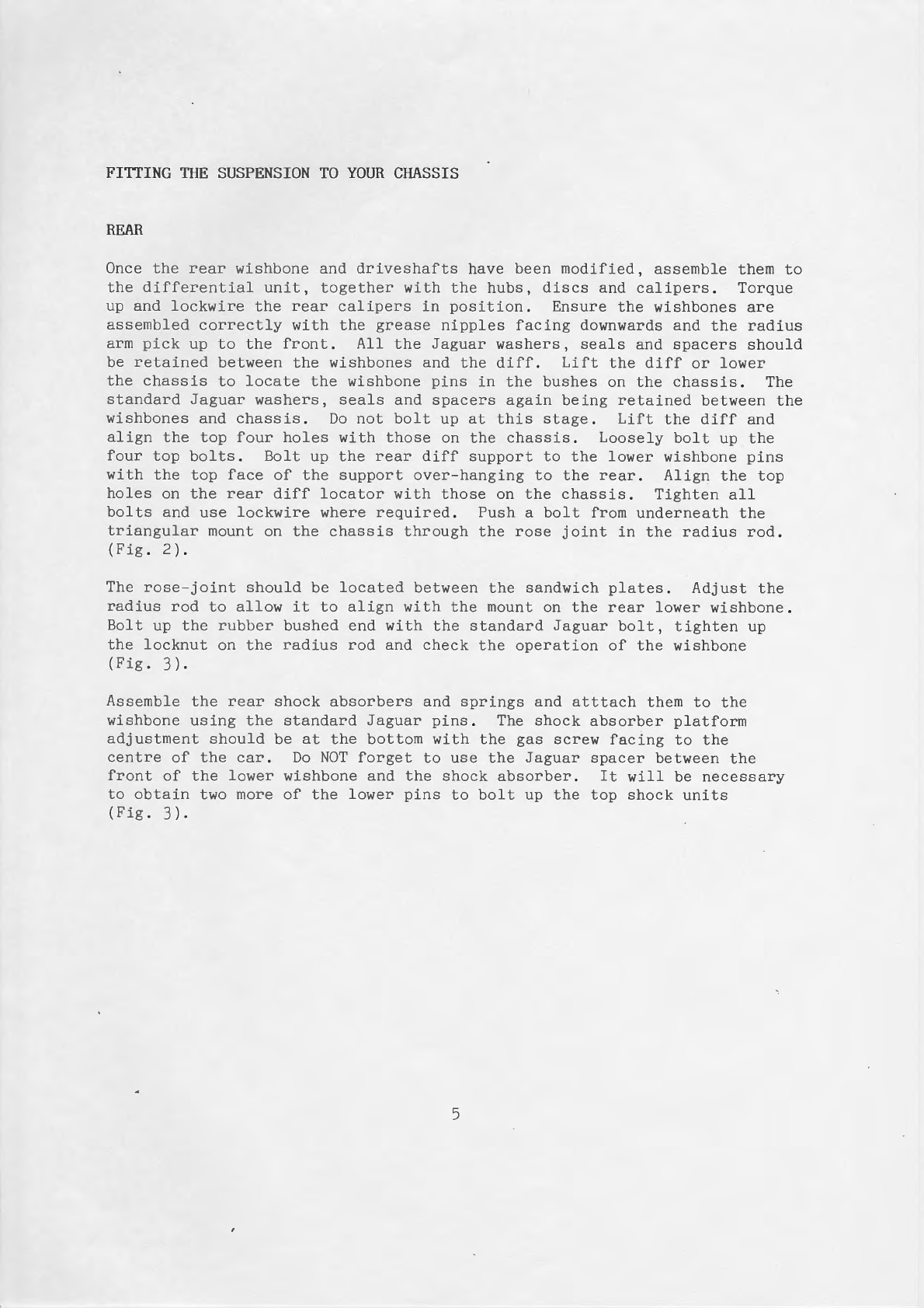
FITTING fiIE SUSPENSION TO YOUR CHASSIS
REAR
Once the rear wishbone and driveshalts have been modified, assembl-e them to
the differential unit, bogether with the hubs, discs and calipers. Torque
up and lockwire the rear calipers in position. Ensure the wishbones are
assembled correctly with the grease nipples facing downwards and the radius
arm pick up to the front. A11 the Jaguar washers, seals and spacers should
be retained between the wishbones and the diff. Lift the diff or lower
the chassis to locate the wishbone pins in the bushes on the chassis. The
standard Jaguar washers, seals and spacers again being retained between the
wishbones and chassis. Do not bolt up at this stage. Lift the diff and
align the top four holes with those on the chassis. Loosely bolt up the
four top boIts. Bolt up the rear diff support to the lower wishbone pins
with the top face of the support over-hanging to the rear. Align the top
holes on the rear diff l-ocator with those on the chassis. Tighten all
bolts and use lockwire where required. Push a bolt from underneath the
triangular mount on the chassis through the rose joint 1n the radius rod.
( Fie. 2) .
The rose-joint should be located between the sandwich plates. Adjust the
radius rod to allow it to align with the mount on the rear lower wishbone.
Bolt up the rubber bushed end with the standard Jaguar bol-t, tighten up
the locknut on the radius rod and check the operation of the wishbone
(Fie.3).
Assemble the rear shock absorbers and springs and atttach them to the
wishbone using the standard Jaguar pins. The shock absorber platform
adjustment should be at the bottom with the gas screw flacing to the
centre of the car. Do NOT forget to use the Jaguar spacer between the
front of the lower wishbone and the shock absorber. It will be necessary
to obtain two more of the 1ower pins to bolt up the top shock units
(Fis. 3).

Fig. 2 Radius Rod into Location with Locknut.
1 Note bolt inserted upside down to
allow witMrawal after body fitment.

Fig. 3 Radius Rod into Wilhlglu
--
1 Note platform adjustment at base,
gas scre\r" faces towards centre of car.

FRONT
Assembfe the front suspension as one unit referring to the Haynes Manual.
It should be noted Lhat the ]ower wishbones have a kink facing forward
(Fig. Il). UolL the lower wishbone to the tube provided on the chassis
using the standard Jaguar bolt, rubbers and washers.
The camber and castor angles can be pre-set at this stage on attachment
of the top wishbone. As a rough guide you should flind a setting of three
washers packed between the wishbone pivot and chassis on the front bolt
together with all three shims to the front between the top balljoint and
wishbone satisfactory (Figs. 5 & 5a). The correct settings are given in
the table aLtached.
The SRC anti roll bar droplinks should now be assembled to the lower shock
absorber plates. The sLandard Jaguar drop link rubbers sandwich the shock
absorber plate. These are retained top and bottom by the Jaguar cup
washers (Fig. 6). These shock plates ca.n now be fitted sandwiching the
lower wishbone.
The anti roll- bar can bow be fitted to the chassj.s using the standard
Jaguar rubbers and clamps. Push the ends of the anti ro11 bar through
the drop linl< ltushes (il may be necessary to raise the suspension to enable
this). 1ltig.'/)
BoIt in the front shocks inserting the hole size reducers located in the
top of the rear Jaguar shocks. The adjustment platform should be at the
bottom with the gas screw facing inwards. BoIt the front speclally
fabricated steering arms to the centre top point on the stub axle carrier
and the top bolting point of the caliper, with the taper pick up for the
track rod lacing forward, pointing towards the disc (the track rod inserLs
from the underside ).
HANDBRAKE LEVER AND CABLE
Bott the handbrake mounting plate from the MGB to the three captive nuts
on the chassis, Lhe ratchet mechanism should be facing forward. Insert
the handbrake and bolt on the cable lever (SRC flabricated) from inside the
transmission tunnel. Connect the handbrake cable to the rear calipers and
handbralie levcr'(inserl"ing the cable adjusting part through the mount on
the chassis). Check the operation of the handbrake. Adjust as necessary
ensuring that the cabLe will not foul with the discs, etc. (Figs. B).

Fig 4 Lower Wishbone.
-
Kink faces forward.
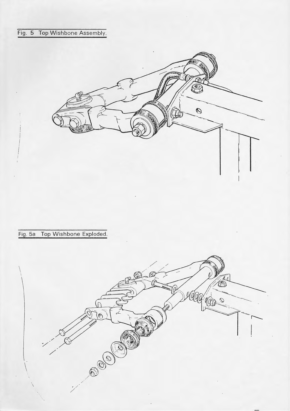
Fig. 5 Top Wis.hbone Assernbly.
Fig. 5a Top Wishbone Exploded.
/
!
\I\I
A}
.^-N)
,o)
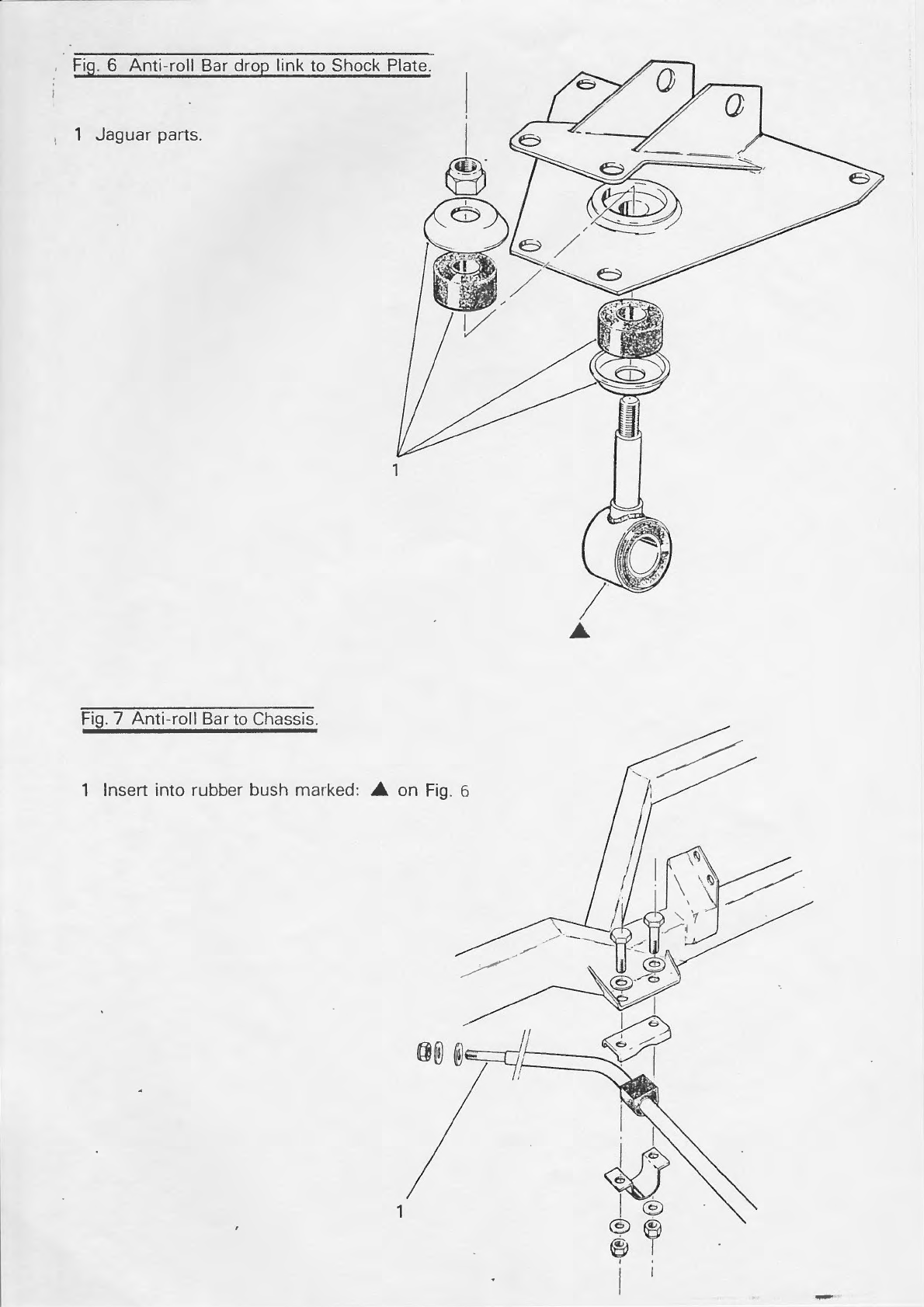
Fig. 6 Anti-roll Bar drop link to Shock Plate.
1 Jaguar parts.
1 lnsen into rubber bush marked: A on Fig. 6

Fig. B Handbrake Cable & Lever.
H

STEERING RACK TO C}I,ASSIS
Take the MGB steering rack (Lg76 onwards, with 22" shaft) and align with
themountsonthechassis.centralisetherack,markanddrillthefour
holes 5/L6" (Fis. 9).
The two track rod extenders are fitted to the ::ack by the removal of the
track rod ends. Screw on the extenders (fitting a locknut on both sides
of the extenders ) and replace the track rod ends '
When adjusting the track of Lhe
sides, and check that there is
exLenders and track rod ends '
car, be sure to evenly adjust from both
always sufficient thread securing the
STEERING COLT]MN
This can Lre pre-fitted prior to body fitment. (Removal is required to fit
the aluminlum panels) The column bolts to the adiustable mounting points
onthechassis.Thetopmountsboltdirectlytothechassiswhilstthe
lower mounts require twt column mounting rubbers (cotton reel type)' The
column extension can be fitted - this requires two Jaguar steering
universar joints. The extension is fitted between the joints, and the
position of the bolt holes marked on the extension' Either file a groove
or a flat on the splines of the extension shalt to allow the bolt to pass
through.
BRAKE I.{ASTER CYLINDER
Pre-fitment of the brake master cylinder and servo unit should be carried
out before bodY fitting.
FuIr instructions for this are supplied in the brake pipe fitting kit'
together with a1l pipes, hoses, "fip", 'T'pieces and silicone brake fluid'
Locate the brake masLer cylinder and servo on the pedal box and temporarily
bolt up ( the unit will have to be slackened off to insert the aluminium
panels once the body has been fitted)' Run the brake pipes as required'
remembering to l.it Ln in-line brake light switch. The pipes shourd run
fr:om the mast.er cylinder, straight back to the footwell and then down the
chussls, irr rtr.tlcr Lo ttti.ttilttisc interference with the exhausts' (Fis' BP3)

Fig.9 Steering Rack & Erctenders

Once the pipes have been fitted and tightened, it is essential that a
silicone brake ftuid with a high boiling point is used, due to the close
proximity of the exhausts. The system should now be bled and inspected for
leaks whilst access is not restricted.
Three pedals are supplied in the body/chassis kit.
A. Throttle - made from round section steel and with
the smal-lest pad.
B. Brake - made from flat steel, with pad in line with
the pivot point.
C. Clutch - made from flat steel with ardog leg'bend
in it (offsetting the pad from. the pivot
point ) .
N.B. ALL LHD CARS SHOTJLD HAVE THO PEDALS OF TYPE B TO OPERATE BNAKE
AND CLUTCH.
The chassis is now complete up to Rolling Chassis specification.
NADIATOR AND FRAME
It is recommended that these are pre-fitted prior to body fitting. This
all-ows you to familiarise yourself with the frame and ensure alignment of
bolt holes. Rover SDl radiator rubber grommets are used at the bottom
of the frame to locate the pins of the radiator. (Fig.lo). Gently bend
upper or lower frame to ease assembly. Top holes marked'2'on Fig. 10
may be enlarged if necessary.

Fig. 1
1 Drill lOmm Hole.
Fig. 2 N,/S caliper with flexipipe.
1 T'piece with brake switch.
Jpl I
I it0

Fis. 3
i Pipe must bend forward at this point
to give clearance from starter motor.
2 Clutch pipe.
3 Rear'pipe.
4 Near side pipe follows lower crossbeam-
5 Offside pipe.
FEU
1 T' is mounted at top & to
rear'of tunnel.
\,,/
N
/P\
\ t\*
\\
>tb
,/e.


