Soutwest Microwave MicroWave 330 User manual

Version 0
Southwest Microwave, Inc.
Security Systems Division
INTREPID™
MicroWave 330
A DIGITAL MICOWAVE
OUTDOOR PERIMETER INTRUSION DETECTION SYSTEM
MicroWave 330 Installation
and Operation Manual

2Version 0
Trademark Notice and Certifications
INTREPID™, MicroPoint™ and MicroTrack™ are registered trademarks of Southwest Microwave, Inc.
Copyright 1995 and 2012 Southwest Microwave, Inc. All rights Reserved.
FCC Notice
MicroWave 330 is classified as a field disturbance sensor.
This device complies with FCC Rules Part 15.245. Operation is subject to the following two conditions:
This device may not cause harmful interference and this device must accept interference received, including
interference that may cause undesired operation.
Notice: changes or modifications not expressly approved by Southwest Microwave, Inc. could void the
user’s authority to operate the equipment.
This equipment has been tested and found to comply with the limits for a Class A digital device, pursuant to
part 15 of the FCC Rules. These limits are designed to provide reasonable protection against harmful
interference when the equipment is operated in a commercial environment. This equipment generates, uses,
and can radiate radio frequency energy and, if not installed and used in accordance with the instruction
manual, may cause harmful interference to radio communications. Operation of this equipment in a
residential area is likely to cause harmful interference in which case the user will be required to correct the
interference at his own expense.
RoHS Compliant
Radiation Safety
The allowable standard minimum of safe radiation exposure level in the United States as established by the
American National Standards Institute is 10mW/cm2. There is currently a proposal to drop this limit to
1mW/cm2. The average Southwest Microwave sensor surface radiation level (when in operation) is
approximately.0186mW/cm2or 1/50 of the proposed lower standard. This level rapidly dissipates at
distances from the unit. For example, at one meter, the figure reduces to .0012mW/cm2 or 1/800 of the
proposed level.
Copyright Southwest Microwave, Inc. May 2012
Southwest Microwave, Inc.
9055 South McKemy Street
Tempe, Arizona 85284-2946
Tel: (480) 783-0201
Fax: (480) 783-0401
Email: infossd@southwestmicrowave.com
Web: www.southwestmicrowave.com

3Version 0
INTREPID™ MicroWave 330 Software
Southwest Microwave, Inc. thanks you for your purchase of the INTREPID MicroWave 330 Digital Microwave
Intrusion Link. Please refer to the Universal Installation Service Tool II (UIST II) for the software setup of this
sensor.
One disk is required to setup the system. It is called:
Universal Installation Service Tool II (UIST II)
This software is used to configure and set-up the system as well as being used for maintenance and
troubleshooting the system.
Software provided by Southwest Microwave, Inc. is subject to the license agreement terms of the individual
product. A copy of the license agreement is available by contacting Southwest Microwave, Inc.

4Version 0
Table of Contents
1. Introduction................................................................................................................................................ 5
2. Hardware.................................................................................................................................................... 5
2.1 MicroWave 330 Link............................................................................................................................ 5
2.2 Optional Power Supplies ...................................................................................................................... 6
2.3 Oprional Accessories............................................................................................................................ 6
3. Principles of Operation and Detection..................................................................................................... 6
3.1 Description............................................................................................................................................ 6
3.2 Range of Operation............................................................................................................................... 7
3.3 Overlaps................................................................................................................................................ 8
3.3.1 High Security Overlaps ................................................................................................................... 9
3.4 Transmitter Block Diagram.................................................................................................................. 9
3.5 Receiver Block Diagram..................................................................................................................... 10
3.6 Specifications...................................................................................................................................... 11
4. Installation Instructions.......................................................................................................................... 13
4.1 Location of MicroWave 330............................................................................................................... 13
4.1.1 Required Area................................................................................................................................ 13
4.1.2 Terrain ........................................................................................................................................... 14
4.1.2.1 Terrain in High Security Applications.................................................................................... 14
4.1.3 Physical Protection........................................................................................................................ 15
4.1.4 Best Security.................................................................................................................................. 15
4.2 Mounting of MicroWave 330............................................................................................................. 16
5. Modes of Operation................................................................................................................................. 18
5.1 Free Running Mode............................................................................................................................ 18
5.2 Tethered Mode.................................................................................................................................... 19
6. Wiring....................................................................................................................................................... 20
6.1 Power Supply Wiring ......................................................................................................................... 20
6.2 Communications Wiring..................................................................................................................... 21
6.3 Tethered Wiring.................................................................................................................................. 21
6.4 Synchronized Wiring.......................................................................................................................... 22
6.5 Remote Test........................................................................................................................................ 23
7. Terminals, Switches and Indicators....................................................................................................... 24
7.1 MicroWave 330T Transmitter............................................................................................................ 24
7.1.1 Channel Select Switch................................................................................................................... 24
7.1.2 External / Internal Modulation Switch .......................................................................................... 24
7.2 MicroWave 330R Receiver ................................................................................................................ 25
7.2.1 Address Switch.............................................................................................................................. 26
7.1.2 Audio Alarm Switch...................................................................................................................... 26
7.2.3 Communications Ports................................................................................................................... 26
8. Connecting the Transmitter and Receiver............................................................................................. 26
8.1 MicroWave 330T Transmitter Connections....................................................................................... 26
8.2 MicroWave 330R Receiver Connections ........................................................................................... 27
9. Alignment and Testing ............................................................................................................................ 27
10. Preventive Maintenance.......................................................................................................................... 28
11. Limited Warranty.................................................................................................................................... 29
12. Returning Equipment under Warranty................................................................................................. 29
13. Returning Equipment fro Non-Warranty Repair................................................................................. 30
14. Replacement Parts................................................................................................................................... 30

5Version 0
1.0 Introduction
The MicroWave 330 is part of the INTREPID™ Series II family of products. It is digital microwave field
disturbance sensor providing perimeter protection for open areas, gates, entryway, walls and rooftop
applications. It provides volumetric detection of human intruders with minimal environmental nuisance alarms.
Advanced digital signal processing (DSP) allows continuous monitoring of intrusion alarm and tamper switch
status, received signal strength for path fault and detection parameters. A system controller such as the Relay
Control Module II (RCM II), Control Module II (CM II), Graphic Control Module II (GCM II), Perimeter
Security Manager (PSM) or SDK (Software Development Kit) is required to poll and configure alarm sources
from MicroWave 330 for annunciation.
MicroWave 330 operates at K-band (24.125 GHz) frequency, achieving superior performance to X-band
sensors. Because K-band is 2.5 times higher the X-band, the multipath signal generated by an intruder is more
focused, and detection of slow-moving intruders is correspondingly better. At K-band frequency, the unit also
has low susceptibility to outside interference from air/seaport radar or other microwave systems.
MicroWave 330 communicates with other INTREPID Series II devices using RS422 communications. This
communication can be done over 22 or 24 gauge stranded shielded twisted pair wire (max 5,000 feet [1,500m]
between devices) or with fiber optic devices. The address of each MicroWave 330 is set by a dip switch on the
receiver circuit board.
MicroWave 330 operates from 10.5 to 60 VDC @ 2.5 Watts with a minimum startup current of 250mA. The
operating currents with standard power supplies are: 12 VDC @ 125mA (Tx) / 208mA (Rx), 24 VDC @ 63mA
(Tx) / 104mA (Rx) and 48 VDC @ 32mA (Tx) / 52mA (Rx).
2.0 Hardware
2.1 MicroWave 330 Digital Microwave Link
Each MicroWave 330 Digital Microwave Link includes a MicroWave 330 Transmitter, Microwave 330
Receiver and two MB62 Universal Mounting Brackets as shown in Figure 1.
MicroWave 330 dimensions are 10.6 in diameter (270mm) and 10.125 in (257mm) front to back (from radome
face to mounting bracket). Each unit weighs 4.5 lbs (2.041kg).
Figure 1 – MicroWave 330 Hardware

6Version 0
2.2 Optional Power Supplies
12 VDC power supply: Model PS13 Power Supply operates from 85-246VAC, 47-63Hz and furnishes 13.6
VDC at up to 2.8A. Power supplies contain automatic switchover and battery charging circuitry for optional
standby batteries of up to 25AH. Temperature rated from 14° to 122° F (-10° to 50° C). UL, ETS, EMC, CE,
RoHS compliant.
12 VDC power supplies: Model PS40 Power Supply operates from 120 VAC, 50-60Hz, 0.5A and furnishes
13.7 VDC at up to 1.6A. Model PS41 Power Supply operates from 220 VAC, 50-60Hz, 0.25A. Both contain
automatic switchover and battery charging circuitry for optional standby batteries of up to 25AH and are fused
on both input and output for maximum protection. Temperature rated from -40° to 150° F (-40° to 66° C).
24 VDC power supply: Model 78B1064 operates from 120VAC to provide 24VDC at 5A with 6.5AH battery
backup. Includes; indoor enclosure 15 x 11 x 4 in. (381 x 280 x 102mm). Temperature rated from 32° to 122° F
(0° to 50° C).
48 VDC power supplies: Model PS48 operates from 120VAC to provide 48VDC at 3A. Includes; indoor
enclosure 14 x 12 x 4 in. (356 x 305 x 102mm). Model PS49 operates from 220VAC to provide 48VDC at 3A.
This supply does not include enclosure. Temperature rated from 32° to 122° F (0° to 50° C). Temperature rated
from 32° to 122° F (0° to 50° C). UL, CSA, TUV, CE compliant.
2.3 Optional Accessories
MB65 Mounting Bracket: Model MB65 is a heavy duty, position locking non corrosive mounting bracket for a
4 inch (102mm) O.D. post.
RS14 Radome: Model RS14 is a shielded radome used to add additional RFI/EMI protection for Microwave
330 transmitter or receiver.
48C15529-A01 Enhanced Reflector: Model 48C15529-A01 is an optional reflector to provide a shorter “dead
zone” to MicroWave 330 transmitter and receiver. This option reduces maximum range to 400 feet (122m).
02A15483-A01 Radome Latch Kit: Model 02A15483-A01 replaces the 6 radome screws for quicker access to
the sensor electronics. Two kits are required for each MicroWave 330 Digital MicroWave Link.
JB70A: Lightning/Surge Protection module protects the data communications and power lines. Includes;
enclosure with terminal strips for wire connections.
3.0 Principles of Operation and Detection
3.1 Description
The MicroWave 330 Transmitter radiates amplitude modulated K-band energy that travels to the MicroWave
330 Receiver where it is detected. A microprocessor and proprietary algorithms provide powerful Digital Signal
Processing to recognize the unique bi-static digital signatures of intruders walking, jumping, running or crawling
through the detection field. Targets are classified and scored in real time at each sensor and stored in the
receiver’s flash memory. When an intruder approaches the beam the energy at the receiver changes in signal
amplitude directly related to the targets size and density allowing the sensor to discriminate between targets.
MicroWave 330 will alarm on average sized humans walking, running or crawling on hands and knees through
the detection pattern. Field adjustments can provide alarm on larger or smaller targets, depending on the specific
site requirements. Operation of MicroWave 330 is illustrated in Figure 2.
7Version 0
Figure 2 – Operation of MicroWave 330 Link
3.2 Range of Operation
A single MicroWave 330 may cover a distance of 800 feet (244m). The receiver is equipped with automatic gain
control (AGC), which automatically adjusts receiver for the distance to be covered and sets the Path Fault
parameter.
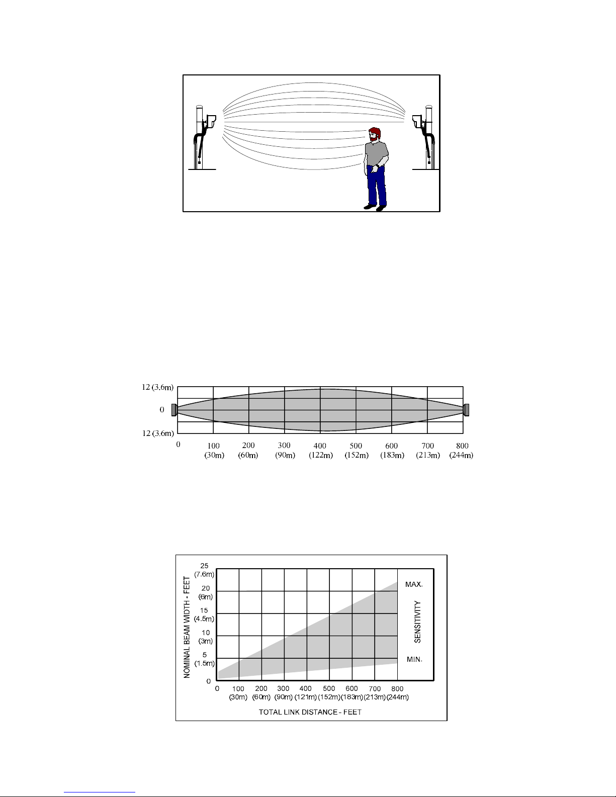
Typical maximum width protection pattern of MicroWave 330 is shown in Figure 3 for mounting height of 2.5
feet (.76m) above smooth earth. Maximum width will be when Transmitter-Receiver distance is at
maximum and Receiver “Sensitivity” control is set to maximum
Figure 3 – Typical Maximum Horizontal Pattern
Figure 4 illustrates how pattern width varies with Transmitter-Receiver distance and sensitivity setting. Actual
patterns will vary somewhat with site topography and surface condition. Generally, lower mounting height or
rougher surface will increase pattern width. For example, if the total link distance is 500 feet (152.4m) and the
sensitivity adjustment set to mid-point, Figure 4 indicates the detection pattern width to be 7.5 feet (2.3m).
Figure 4 – Typical Maximum Horizontal Pattern

8Version 0
Vertical protection pattern will also depend upon Transmitter-Receiver distance, mounting height and
“Sensitivity” setting. Actual patterns will vary somewhat with site topography and surface condition. Typical
pattern height is 50 to 75% of pattern width. Approximate vertical protection pattern is shown in Figure 5. For
example, at 50 feet (15m) with minimum sensitivity the pattern height is 5 feet (1.5m).
NOMINAL BEAM HEIGHT - FEET
20
(6m)
15
(4.5m)
10
(3m)
5
(1.5m)
0
DISTANCE - FEET
50
(15m)
100
(30m)
150
(45m)
200
(60m)
250
(76m)
300
(90m)
0350
(107m)
400
(121m)
SENSITIVITY
MAX.
MIN.
25
(7.6m)
Figure 5 – Typical Vertical Pattern
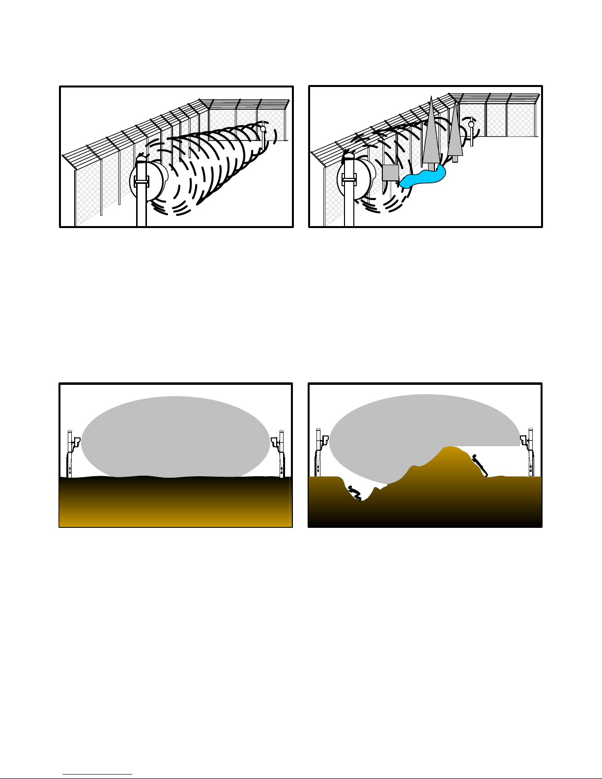
3.3 Overlaps
Protection pattern below centerline will tend to fill area between beam centerline and ground except for a “dead
zone” immediately in front of and below Transmitter and Receiver. This zone is best protected by overlapping
links at ends and corners as shown in Figures 6.
Figure 6 – Overlaps and Dead Zone
Corner overlaps should be 30 feet (9.2m) minimum. Intermediate or in line overlaps should be 60 feet (18.3m)
minimum with a beam centerline offset of 18 to 20 inches (46-51cm). Basket weave overlaps should be 60 feet
(18.3m) minimum and a minimum of 5 feet (1.5m) off the fence (except for corners).
9Version 0
Figure 7 shows amount of overlap required to detect against hands and knees crawling intruders, as a function of
“Sensitivity” setting. It is always recommended to keep the sensitivity setting at the lowest possible value to
minimize nuisance alarms but maintaining a high probability of detection.
DEAD ZONE - FEET
Figure 7 – Sensitivity vs Dead Zone
3.3.1 High Security Overlaps
For maximum-security applications where detection of prone “commando style” crawl is required, the
intermediate over-lap should be 60 feet (18.3m) minimum with parallel beam centerline offset of 18 inches
(46cm) maximum. The corner overlaps should be 30 feet (9.2m) minimum. Terrain flatness should be no more
than plus three inches or minus three inches deviation from a plane drawn between the transmitter and receiver.
The zone length (Transmitter to Receiver) should not exceed 400 feet (122m).
High security applications also use stacked link configurations to meet site requirements. A stacked link may
consist of two or more MicroWave 330 links or used in combination with the Model 300B link which operates
at X-band frequency of 10.525 GHz. A stacked link greatly reduces the dead zone and increases PD.
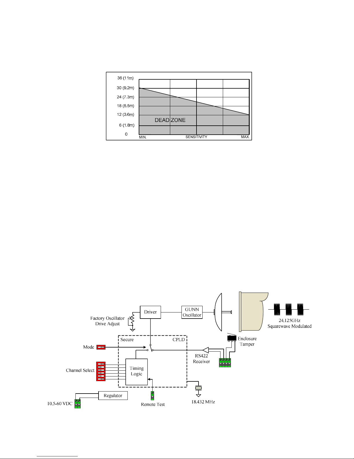
3.4 Transmitter Block Diagram
MicroWave 330T Transmitter consists of two major subassemblies – RF Assembly and Transmitter Circuit
Board. A block diagram is shown in Figure 8.
Slave
Modulation
Tamper
Figure 8 – MicroWave 330 Transmitter

10 Version 0
The RF assembly consists of a Gunn oscillator, which generates K-band microwave energy and the parabolic
antenna system. The Transmitter circuit board contains voltage regulator and modulation circuit to drive the
microwave oscillator and a secure CPLD. Modulation frequency in Free Run Mode is selected from one of six
channels (A, B, C, D, E, and F) by a dip switch on the Transmitter Circuit Board.
The CPLD is responsible for the generation of the asynchronous modulation frequencies when the “Mode”
switch is set to “Internal” position and also for determining the quality of the signal provided on the tether when
the “Mode” switch is set to “External” position.
A “Test” terminal is provided on the Transmitter Circuit Board. Application of 5.0 to 14.0 VDC will cause
Transmitter to turn off and illuminate the red “Channel Error” LED, generating a test alarm at receiver. A green
LED on Transmitter Circuit Board indicates that power is on.
3.5 Receiver Block Diagram
MicroWave 330R Receiver consists of two major subassemblies – RF Assembly and Receiver Circuit Board. A
block diagram is shown in Figure 9.
~
~
~
∫
+
-
+-
+
+
-
Secure
24.125Ghz
Squarewave Modulated
Cavity
Det.
Bias
Low Noise BPF
30dB
AGC
5th
LPF
1st
LPF Level
Shift VCXO CLK
(I)
(Q)
18.432 MHz
HPF Jam
HPF Wrong
Channel
Power
Supply
10.5-60VDC
Sync
TX +
RX -
TX -
RX +
TX +
TX -
Channel
Modulation
CLK
Secure
CPLD
Timing
Logic
RS232
Configuration
Port Com 1
RS422
Alarm
Network
Com 2
RS422
Alarm
Network
TX +
RX -
TX -
RX +
TX +
TX -
RX -
RX +
Gnd
Gnd
Watchdog
CPU
Align (ADC)
Target (ADC)
PS (ADC)
Memory
(optional)
Enclosure
Tamper
HI
External
Tamper
LO
Node Address
BDM
Reset
RTC
Figure 9 – MicroWave 330 Receiver

11 Version 0
MicroWave 330R Receiver RF Assembly consists of a parabolic antenna (identical to antenna of Transmitter)
and a Schottky diode detector. The detector converts modulated K-band energy from Transmitter into a low
frequency signal for processing by Receiver Circuit Board.
The received audio signal is amplified by an automatic gain control (AGC) preamplifier enabling the
preamplifier output to be held to a constant level regardless of Transmitter Receiver distance (distance must be
within maximum distance of link). This also set the “Path Fault” alarm parameter.
The detector output is a voltage level that is held constant under normal conditions by the slow-acting AGC
loop. Rapidly changing signal strength caused by a target moving into the microwave beam is not affected by
AGC loop and causes an AC signal to appear at the detector output. Signal is amplified, filtered, digitized and
compared with detection parameters.
Whenever signal matches the detection parameters, an alarm is generated. “Sensitivity” is adjusted in the UIST
II software program.
Microwave 330R Receiver is equipped with various alignment and troubleshooting features. Alignment voltage
test point provides a DC voltage proportional to received signal strength that may be measured with an ordinary
VOM. It is usually viewed in the UIST II software program.
A red “Alarm” LED lights whenever an intrusion occurs. A red “Wrong Channel” LED lights whenever
Transmitter and Receiver are set to different modulation channels. A red “Jam” LED lights when a secondary
interfering signal is present. A red “Pulse” LED indicates the application program is running. There are also
LED’s for communications status of the RS422 and RS232 ports.
3.6 Specifications
1.0 Detection Capability
1.1 Range: 100 feet (30.5m) to 800 feet (244m).
1.2 Beam Diameter: 2 feet (.6m) to 22 feet (6.7m) depending upon link distance and “Sensitivity” setting
per Figure 4.
1.3 Target: 77 pound (35kg) human – walking, running, hands and knees crawling or jumping. Prone
crawling or rolling 77 pound (35kg) human or simulated with a 12-inch (30cm) diameter metal
sphere detected at maximum range of 400 feet (122m) with flat terrain.
1.4 Minimum Target Velocity: 0.1ft. /sec. (30mm/sec.)
1.5 Maximum Target Velocity: 50ft. /sec. (15m/sec.).
2.0 Reliability
2.1 Equipment False Alarm Rate: 1/year/unit based upon signal-to-noise ratio at maximum sensitivity
setting.
2.2 Probability of Detection: 0.99% minimum on 77-pound (35kg) human upright or on hands and knees.
2.3 Self Supervision: Alarm on failure (inherent in design, fully self-supervised) and remote test.

12 Version 0
2.4 Automatic Gain Control: Link automatically adjusts to slow changes in path loss due to environment.
AGC range: -60dB.
2.5 Cross Modulation: When installed in accordance with following installation instructions cross
modulation (interference) from adjacent links will be 25dB below primary signal.
3.0 Transmittal Signal
3.1 Radiated Power: 33Bm peak EIRP (maximum), square wave modulated.
3.2 Carrier Frequency: K-band 24.125GHz.
3.3 Modulation Frequencies: Six field-selectable modulation frequencies.
3.4 Above specifications for USA are in accordance with F.C.C. regulations part 15.245.
4.0 Power Requirement
4.1 Voltage: 10.5 to 60.0VDC 2.5W maximum (Tx or Rx).
4.2 Current: Transmitter and Receiver under normal ambient operating conditions:
12 VDC: Tx @ 125mA – Rx @ 208mA
24 VDC: Tx @ 063mA – Rx @ 104mA
48 VDC: Tx @ 032mA – Rx @ 052mA
4.3 Transmitter fused for 0.25 amps and Receiver fused for 0.5 amps.
5.0 Alarm Indication
5.1 Red Alarm LED.
5.2 Red Jam LED.
5.3 Red Wrong Channel LED.
5.4 Audible alarm with Sonalert.
5.4 Tamper Switch, Transmitter and Receiver: Form C contacts rated 2.0 amps at 28 VDC.
6.0 Alignment and Test Aids
6.1 Alignment Voltage: Available in software or at Receiver Test Point. Positive voltage, suitable for
100,000 ohms/volt VOM, increases with receiver signal strength. Range 0.5-5.0 VDC.
6.2 Wrong Channel LED: Red LED on Receiver board lights when Transmitter and Receiver set to
different channels.
6.3 Jam LED: Red LED on Receiver board lights when receiver is receiving multiple RF sources.
6.4 Pulse LED: LED on Receiver board blinks showing the application software is running.
6.5 Communication LED’s: Green LED’s on Receiver board to indicate RS422 and RS232 transmit and
receive communication polls.

13 Version 0
6.6 Transmitter “ON” LED: Green LED on Transmitter circuit board indicates that power is on.
6.7 Channel Error LED: Red LED on Transmitter to indication Tx/Rx set to different modulation
channel or Remote Test is on.
7.0 Communications Ports
7.1 1 - RS232 configuration port. 2 – RS422 communications ports.
8.0 Weight, Transmitter, or Receiver: 4.5 pounds (2.04kg). Shipping weight 18 pounds (8.2kg)
9.0 Operating Environment
8.1 Temperature: -40° F to +150° F (-40° C to +66° C)
8.2 Relative Humidity: 0 to 100%.
10.0 Dimensions (Transmitter or Receiver)
Figure 10 – MicroWave 330 Transmitter or Receiver Dimensions
4.0 Installation Instructions
4.1 Location of Microwave 330
4.1.1 Required Area
MicroWave 330 must be located in an area which is free of obstructions and moving objects such as chain link
fences parallel to the detection field, trees, bushes and large areas of water as shown in Figure 11. Large moving
objects within the protection pattern will be indistinguishable from an intruder and will cause nuisance alarms.
The clear area required for a MicroWave 330 installation depends upon the distance to be covered by the link.
Protection patterns for various conditions are given in Figures 4. In each installation the clear area must be at
least as large as the maximum protection pattern.
14 Version 0
DO DONT
Figure 11 – Clear Area
4.1.2 Terrain
Since the operation of Link requires transmission of energy from Transmitter to Receiver, it is important to
maintain a clear line of sight between the units. Therefore, the ground must be flat across the protected area.
Any bumps, hills or ditches in the area will shadow the beam and may provide crawl space for an intruder.
Bumps or hills must be leveled, and ditches filled so that the area is flat to within six (6) inches (15cm) as shown
in Figure 12.
DO DONT
Figure 12 – Terrain
The protected area can be any stable, reasonably smooth material such as concrete, asphalt, tilled earth or gravel.
If there is grass or vegetation in the protected area it must be kept cut to a maximum of three (3) inches (8cm) in
height. Snow accumulation should not exceed three (3) inches (8cm) in height. MicroWave 330 should
not be operated over open water.
4.1.2.1 Terrain in High Security Applications
For maximum-security applications where detection of prone “commando style” crawl is required, the terrain
flatness should be no more than plus three inches or minus three inches deviation from a plane drawn between
the transmitter and receiver. The zone length (Transmitter to Receiver) should not exceed 400 feet (122m).

15 Version 0
4.1.3 Physical Protection
Install the Transmitter and Receiver in locations that provide protection from accidental damage as well as from
tampering. Simple devices such as bumper posts or parking guards may be used to protect equipment from
damage from vehicles as shown in Figure 13.
DO DONT
Figure 13 – Physical Protection
4.1.4 Best Security
Choose the location that will provide best security, yet be free from false nuisance alarms. Always locate
MicroWave 330 inside a controlled access area to prevent unwanted nuisance alarms due to random foot traffic,
vehicles, or large animals. Typically, units should be mounted 2 ½ to 3 feet (0.76-0.91m) above ground level,
and far enough inside fence to provide a clear area of protection as shown in Figures 14 & 15.
For maximum security it is necessary to overlap the ends of links so that the “dead zone” below and
immediately in front of the adjoining link is protected. A 60-foot (18m) overlap is recommended at intermediate
points, and a 30-foot (9.2m) overlap is recommended at corners. If site demands shorter overlap, increased
sensitivity will reduce dead zone, per Figure 7, but will also widen beam, per Figure 4.The offset of overlapping
links in line should be 18 inches (46cm) as shown in Figure 6. Additional protection may be added at critical
points by installing SOUTHWEST MICROWAVE, INC. Model 380 or 385 Transceiver, Model 415 PIR,
MS15/MS16 Dual Tech sensor or stacking MicroWave 330 links or stacking with Model 300B microwave link.
DO DONT
Figure 14 – Best Security

16 Version 0
Figure 15 – Overlapping Links
Note from Figure 15 that at each point of overlap either two Transmitters or two Receivers are installed. This
arrangement prevents an adjacent Transmitter and Receiver from establishing an unwanted link across the short
overlap distance. If there is an odd number of links in an installation, a transmitter and receiver will need to be
overlapped. This should be done in a corner as shown in Figure 15. Alternatively the synchronization capability
in MicroWave 330 could be utilized.
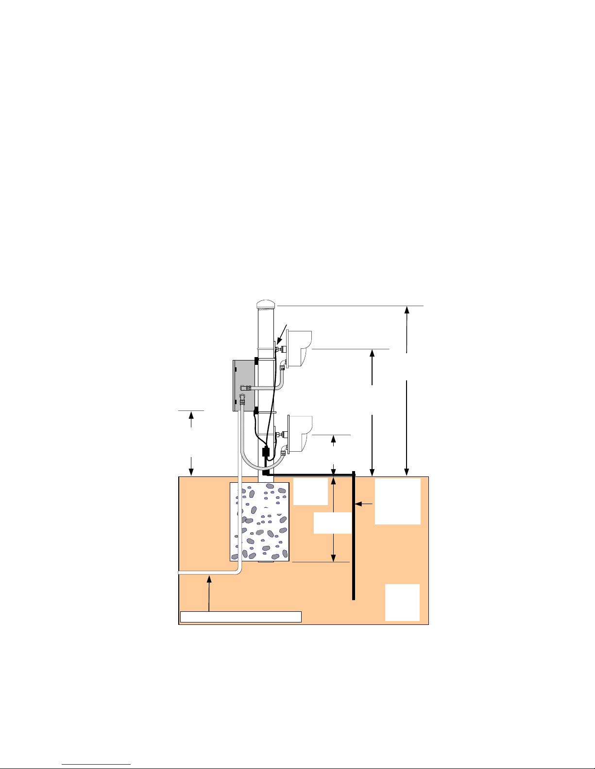
4.2 Mounting Microwave 330
Prepare a rigid mounting surface for the MicroWave 330 Transmitter and Receiver as shown in Figure 16.
Ground Lug
1/2" (1.3cm)
Flexible
Conduit
4" (10.2cm) O.D.
Galvanized Pipe
Cap
Gnd. Lug & Wire
#6 AWG
Ground Bus
Install Per Local
Electrical Code
Concrete
Tamper, Com, Sync and Power Lines
24" (61cm)
Grounding
Rod
per Local
Electrical
Code
36"
(0.91m)
Nominal
48"
(1.22m)
Nominal
Figure 16 – Mounting Detail
17 Version 0
Do not mount units on a cyclone fence or any vibrating surface. A recommended mounting post is a 3 ½ inch
(9cm) galvanized pipe (outside diameter 4 inches, 10cm), sunk into the ground in a concrete base, and
protruding above ground level to a height of 4 feet (1.2m). Mount the Transmitter and Receiver 2 ½ to 3 feet
(0.76 to 0.91m) above ground level and allow for height adjustment of at least plus or minus 6 inches (15cm).
Height adjustment may be required during final alignment to achieve optimum protection pattern. An 18-inch
(46cm) ½ inch (1.3cm) flex conduit is recommended between conduit fitting of T/R and rigid conduit.
Stacking MicroWave 330
For high security applications where “prone crawl” detection is required, the MicroWave 330 can be stacked to
provide a high probability of detection with a very low nuisance/false alarm rate and a reduction in dead zone as
shown in Figure 17.
To eliminate mutual interference between links, one link can be rotated 90° to change the polarity from an E-
plane (vertical polarization) to an H-plane (horizontal polarization) which will cross polarize the waveguides to
eliminate potential interference. MicroWave 330 includes synchronization circuitry that can also be utilized to
eliminate potential interference.
1/2" (1.3cm)
Flexible
Conduit
4" (10.2cm) O.D.
Galvanized Pipe Gnd. Lug & Wire
BX20 or BX35
Junction Box
(optional)
Grounding
Rod
per Local
Electrical
Code
Install Per
Local
Electrical
Code
330
330
#6 AWG
Ground
Bus
Cap
Concrete 24"
(61cm)
Tamper, Com, Sync and Power Lines
36"
(0.91m)
Nominal
48"
(1.22m)
Nominal
12" (30cm)
Nominal
17"
(43.2cm)
Nominal
Figure 17 – Stacked Mounting Detail
1. Remove the MicroWave 330 T/R Link(s) from the shipping containers. Separate the swivel assembly
from the mounting plate by turning the large nuts counter-clockwise. Large nuts require 1 ¼ inch
(32mm) open-end wrench.
18 Version 0
2. Secure the mounting bracket to the post with U-bolt or to other mounting surface with appropriate
screws or fasteners.
3. Secure the swivel assembly to MicroWave 330 Transmitter and Receiver and attach to mounting
bracket.
4. Rotate the MicroWave 330 Transmitter and Receiver so that the conduit fittings are pointed straight
down.
5. Tighten the large nuts on the swivel assembly to hold the units in place.
5.0 Modes of Operation
MicroWave 330 has two modes of operation. One is the Normal Free Running configuration and the other is the
Tethered configuration. In either configuration a controller is required for operation. The controllers that can be
used are the Relay Control Module II (RCM II), Control Module II (CM II), Graphic Control Module II (GCM
II), and Perimeter Security Manager (PSM) or a third party SDK development. See controller manuals for more
information.
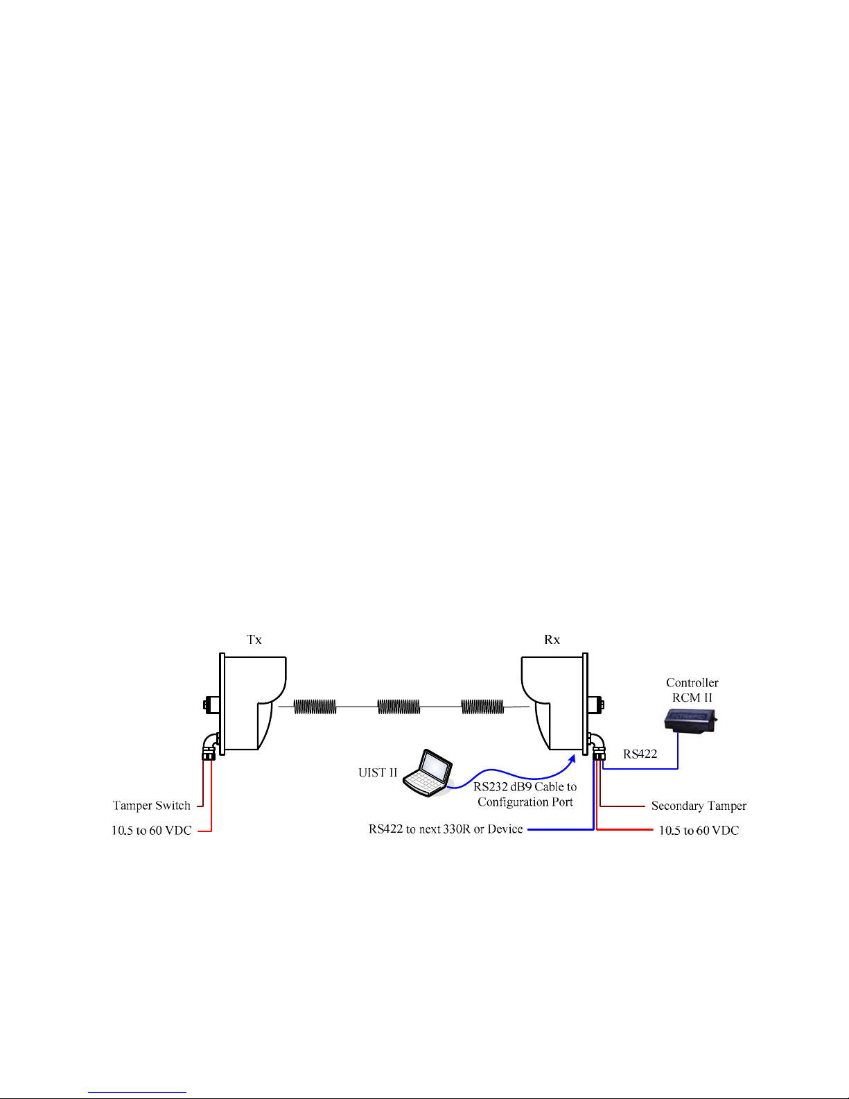
5.1 Free Running Mode
In the Free Running mode the controller and laptop are connected to the MicroWave 330 receiver as shown in
Figure 18. MicroWave 330 setup and detection parameters are configured using the Universal Installation
Service Tool II (UIST II) running on a laptop or desktop computer connected to the RS232 Configuration Port,
Com 3. Alarm reporting is configured at the controller and is communicated on the RS422 alarm polling
network, Com 1 and Com 2. If a CM II or GCM II controller is used, MicroWave 330 can be configured using
the UIST II through the controller.
Figure 18 – Free Running
In the Free Running mode the MicroWave 330 transmitter and receiver are independently configured. The
transmitter and receiver must have their modulation channel set to the same modulation frequency. The tamper
switch from the transmitter is monitored independently. The receiver has two tamper switches. One can be
monitored over the alarm polling network and the other can be monitored independently. A typical Free Run
configuration using an RCM II as the controller and a Relay Output II (ROM II) module is show in Figure 19.
Optionally an AIM II can be used to monitor transmitter tampers. Note: power wiring has been left off this
example for clarity.

19 Version 0
RECEIVER
TRANSMITTERRECEIVER
TRANSMITTERTRANSMITTER RECEIVER
RCM IIROM II
RS422 To Alarm Panel
Tampers to Alarm Panel Tampers to Alarm Panel
Tampers to Alarm Panel
Figure 19 – Free Running Example
5.2 Tethered Mode
In the Tethered mode the controller and laptop are connected to the MicroWave 330 receiver as shown in Figure
20. MicroWave 330 setup and detection parameters are configured using the Universal Installation Service Tool
II (UIST II) running on a laptop or desktop computer connected to the RS232 Configuration Port, Com 3. Alarm
reporting is configured at the controller and is communicated on the RS422 alarm polling network, Com 1 and
Com 2. If a CM II or GCM II controller is used, MicroWave 330 can be configured using the UIST II through
the controller.
Figure 20 – Tethered Mode
The Tethered mode requires a wire connection between the transmitter and receiver for synchronous operation.
The modulation signal from the receiver is provided on the tether to the transmitter and the transmitter tamper is
wired into the External Tamper Input on the receiver so it is included in the alarm polling network. The tether
also allow for changing the modulation frequency using the UIST II.

20 Version 0
Also available in the tethered mode is synchronization. MicroWave 330 incorporates synchronization circuitry
that provides time division multiplexing so multiple links and Model 380 or Model 385 microwave transceivers
can be used in close proximity without mutual interference. Two (2) MicroWave 330 links and seven (7)
transceivers can be connected on the sync line.
A typical Tethered configuration using a CM II as the controller and a ROM II is show in Figure 21. Note:
power wiring has been left off this example for clarity.
RECEIVER
TRANSMITTERRECEIVER
TRANSMITTERTRANSMITTER RECEIVER
CM IIROM II
RS422 To Alarm Panel
Tether
Figure 21 – Tethered Configuration
6.0 Wiring
6.1 Power Supply
MicroWave 330 operates from 10.5 to 60 VDC @ 2.5W. The operational current rating with standard power
supplies are: 12 VDC @ 125mA Tx / 208mA Rx, 24 VDC @ 63mA Tx / 104mA Rx and 48 VDC @s 32mA
Tx / 52mA Rx. Figure 22 shows the typical voltage drop for a 500 foot (152.4m) length of cable using various
wire gauges.
Figure 22 – Voltage Drop
Table of contents


