–5 –
Parts, Tools, Materials
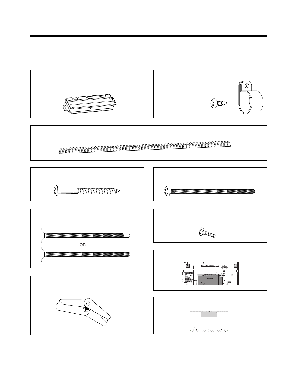
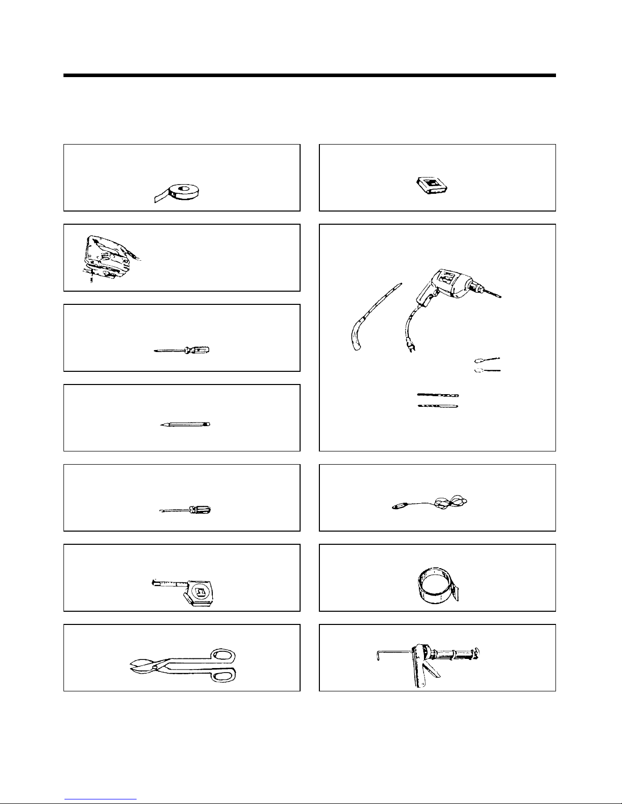
THE FOLLOWING PARTS ARE SUPPLIED WITH THE OVEN:
NOTE: Depending on your ventilation requirements, you may not use all of these parts.
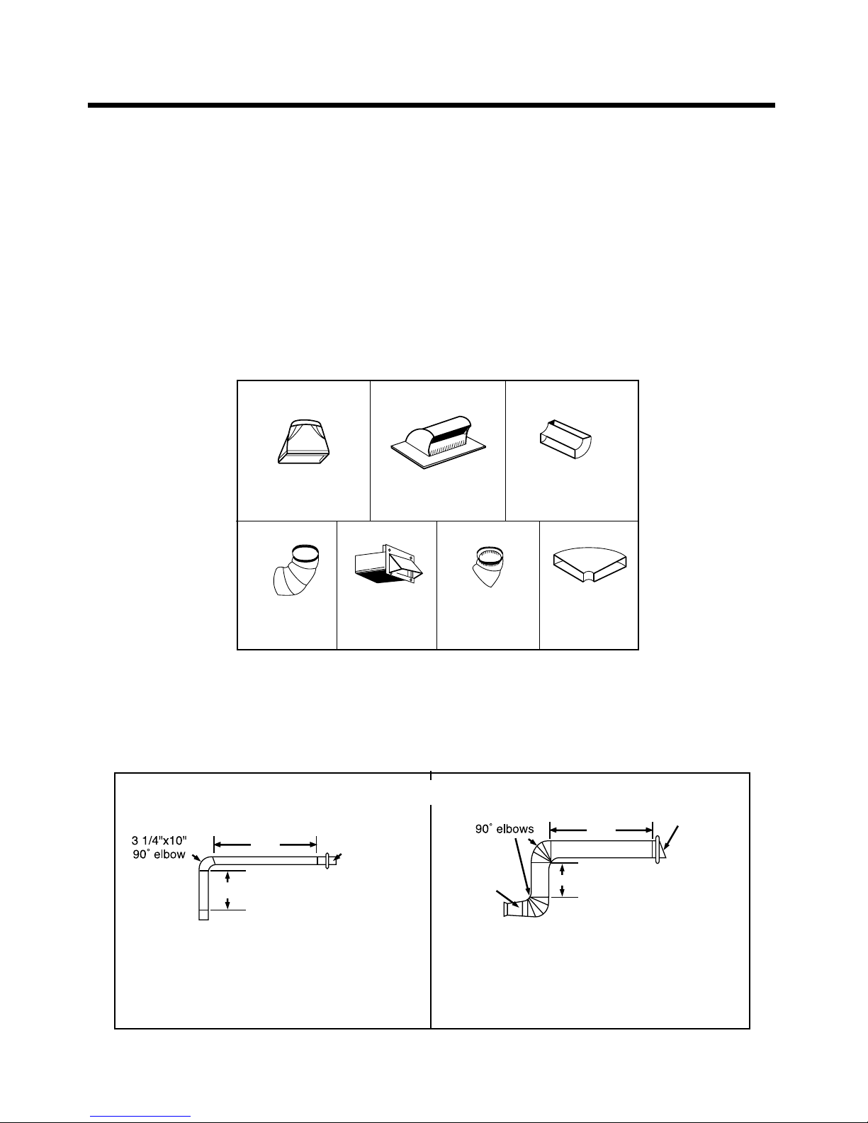
Damper/duct connector
(for roof venting or wall venting installation)
Not Actual Size (2 pieces must be assembled as
shown) Not used if venting into kitchen.
One power cord clamp and
One dark-colored mounting screw
(to hold the power cord)
Actual Size
Four 1/4" x 2" lag screws - Actual Size
(for wall stud holes)
Three 1/4" x 3" toggle bolts - Actual Size
(for drywall holes)
Two 1/4" x 3" bolts - Actual Size
(for securing to the upper cabinet
Three 1/4" x 3" bolts - Actual Size
(for securing to the upper cabinet)
Two tapping screws - Actual Size
(for attaching the damper duct connector)
One upper cabinet template- Not Actual Size
One rear wall template- Not Actual Size
(1piece mounting plate only)
One power cord clamp bushing - Actual Size (for the cord hole in a metal upper cabinet)
NOTE: You need to install at least one lag screws into a 2" x 4" stud and three anchor bolts into the wall.
and the mounting area must meet the 150 lbs. weight requirement.
D
A B
C
4922W5A060E
PrintedinChina
NOTE:IT IS VERY IMPORTANTTO
READAND FOLLOW THE DIRECTIONS
INTHE INSTALLATIONINSTRUCTIONS
BEFOREPROCEEDING WITH THIS
REARWALL TEMPLATE.
1.Placethe template flat against the rear
wall,aligningthe circles Aand Bwith the
correspondingholespreviously drilled in the
rearwallfor holes A and B of the wall plate.
2.Withthe template aligned to the holes, tape the
templatetothe rear wall.
3.Usea saber or keyhole saw to cut out the shaded
areaF.through the rear wall.
4.Removethe template from the rear wall.
5.RETURNTO AND PROCEED WITH THE
INSTALLATIONINSTRUCTIONS.
1/4″
12
4
F. CUT OUT FOR WALL
VENTED ONLY
CUTHOLE THROUGH REAR WALL FOR EXHAUST ADAPTOR
REAR WALL TEMPLATE
Locateandmarkholes to align with holesin the
mountingplate.
IMPORTANT:
LOCATEATLEASTONE STUD ON EITHER SIDE OF
THECENTERLINE.
MARKTHELOCATIONFOR 2 ADDITIONAL, EVENLY
SPACEDTOGGLEBOLTSIN THE MOUNTING PLATE
AREA.
C
L
Locateandmark holes to alignwith holes in the
mountingplate.
IMPORTANT:
LOCATEATLEAST ONE STUD ON EITHERSIDE OF
THECENTERLINE.
MARKTHELOCATIONFOR 2 ADDITIONAL,EVENLY
SPACEDTOGGLEBOLTS IN THE MOUNTING PLATE
AREA.
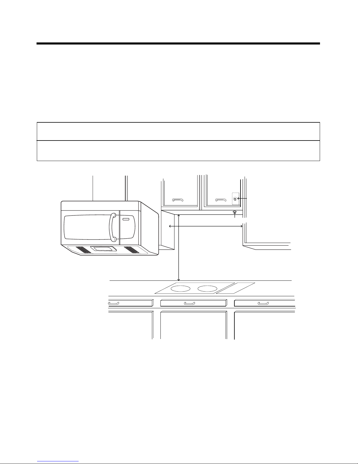
30
″
MINIMUM WIDTH REQUIRED
CAUTION– IF EXHAUST ADAPTOR IS POSITIONED OUTSIDE
RECOMMENDEDDIMENSION, GREASE-LADEN AIR WILL
DISCHARGEINTO HOUSE STRUCTURE.


 User manual")


M Service manual")


