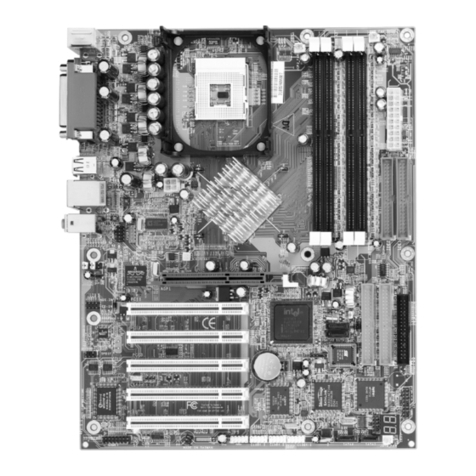
Soyo Computer SY-7IWM User manual

SY-7IWM
SY-7IWM/M
Motherboard
Quick Start Guide
Hardware
Installation
Quick BIOS
Setup
Introduction
The SOYO CD
Aureal Sound
Driver
Installation
The MR
Drivers
Installation

SOYO™
2
SY-7IWM & SY-7IWM/M Motherboard
Socket 370 for Intel Celeron
TM
processors
Intel FW82810 AGP/PCI/AMR Motherboard
100 & 66 MHz Front Side Bus supported
Micro ATX Form Factor
Copyright © 1999 bySoyo Computer Inc.
Trademarks:
Soyo is the registered trademark of Soyo Computer Inc. All trademarks are the properties of
their owners.
Product Rights:
All names of the product and corporate mentioned in this publication are used for identification
purposes only. The registered trademarks and copyrights belong to their respective companies.
Copyright Notice:
All rights reserved. This manual has been copyrighted by Soyo Computer Inc. No part of this
manual may be reproduced, transmitted, transcribed, translated into any other language, or
stored in a retrieval system, in any form or by any means, such as by electronic, mechanical,
magnetic, optical, chemical, manual or otherwise, without permission in writing from Soyo
Computer Inc.
Disclaimer:
Soyo Computer Inc. makes no representations or warranties regarding the contents of this
manual. We reserve the right to amend the manual or revise the specifications of the product
described in it from time to time without obligation to notify any person of such revision or
amend. The information contained in this manual is provided to our customers for general use.
Customers should be aware that the personal computer field is subject to many patents. All of
our customers should ensure that their use of our products does not infringe upon any patents. It
is the policy of Soyo Computer Inc. to respect the valid patent rights of third parties and not to
infringe upon or to cause others to infringe upon such rights.
Restricted Rights Legend:
Use, duplication, or disclosure by the Government is subject to restrictions set forth in
subparagraph (c)(1)(ii) of the Rights in Technical Data and Computer Software clause at
252.277-7013.
About This Guide:
This Quick Start Guide can help system manufacturers and end users in setting up and installing
the Motherboard. Information in this guide has been carefully checked for reliability; however,
to the correctness of the contents there is no guarantee given. The information in this document
is subject to amend without notice.
For further information, please visit our Web Site on the Internet. The address is
"http://www.soyo.com.tw".
7IWM & 7IWM/M Serial - Version 1.0 - Edition: June 1999
*Thesespecificationsaresubjecttoamendwithoutnotice

SY-7IWM & SY-7IWM/M
Quick Start Guide
3
Introduction
1
1
Introduction
Congratulationsonyourpurchaseofthe
SY-7IWMorSY-7IWM/M
Motherboard.ThisQuick
StartGuideillustratesthestepsforinstallingandsettingupyournewMotherboard.
ThisguideprovidesalluserswiththebasicstepsofMotherboardsettingandoperation.For
furtherinformation, pleaserefertothe SY-7IWM&SY-7IWM/MMotherboardUses’Guide
thatcamewithyour Motherboard.
Unpacking
WhenunpackingtheMotherboard, checkforthe followingitems:
u
TheSY-7IWMorSY-7IWM/MFW82810AGP/PCI/AMR
Motherboard
u
ThisQuickStart Guide
u
TheInstallation CD-ROM
u
OneIDEDeviceATA66FlatCable
u
OneFloppyDisk DriveFlatCable
u
Serialportflat cablewith a9-pinconnector bracket
uModemRiserCard (Optional)
LINE
PHONE

SY-7IWM & SY-7IWM/M Quick Start Guide
4
Introduction
SY-7IWM & SY-7IWM/M Motherboard Layout
(Optional)
VGA
PRT
PS/2 KB
Connector
PS/2 Mouse
Connector
PCI Slot #1
PCI Slot #3
AMR
3V
Lithium
Battery
1
CPUFAN
1PWRFAN
Winbond
W83627HF
-AW
IDE 2 IDE 1
1
1
1
FDC
ATX Power
LINE-OUT
LINE-IN
MIC JACK
JOYSTICK
JP2
J6
JP15
1
2
5
64
3
JP44
WOL
Header
31
Intel
FW82810
J9 CD-IN
J11
PHONE-IN
J10
AUX-IN
1
Socket 370
JP5
DIMM 1
DIMM 2
DIMM 3
COM1COM2
PCI Slot #2
1
1
4
4
4
CODEC
AC97
AU8810
Aureal
Intel
Fw82801
Intel
82802AB
4MB
IR1
1
1
5
5
SDRAM
SDRAM
1
3
1
CHAFAN
Speaker
Keylock
Power
LED
ACPI
LED
HDD
LED
_
+
_
+
_
+
_
+
Reset
PWRBT
CMOS Clear
Jumper
13
USB 3
USB 1
USB 2
(Optional for 7IWM only)

SY-7IWM & SY-7IWM/M
Quick Start Guide
5
Introduction
Key Features
Ø
SupportsIntelCeleron™processors
(300A-500MHz)
Ø
Supports100&66MHzFrontSideBus
Frequency
Ø
Auto-detectCPUvoltage
Ø
AdjustableCPUCoreVoltage(Normal,
4%,6%)
Ø
Chipsetintegrated3DAGPAccelerator
Ø
EasyCPUsettingsinBIOSwiththe
“SOYOCOMBOSetup”
Ø
Easyover-clockingwiththe“SPORT”
modesetting
Ø
AurealAu8810Audio(SY-7IWMonly)
Ø
PC98,ACPI
Ø
UltraDMA/66(ATA 66)
Ø
SupportsWake-On-LAN(WOL)
Ø
SupportsACPISuspendIndicator
Ø
SupportSuspendToDRAM(STR)for
instantlyAvailable/OnNowEaseofPC
implementation(optional)
Ø
Power-onbymodem,alarm,PS/2
KeyboardandMouse*
Ø
Powerfailureresume
Ø
Supportsonboardhardwaremonitoring
andincludes Hardware Doctor™utility
Ø
Fanspeedcontrol
Ø
BatteryLowvoltage Detect
Ø
Support7setsofvoltagemonitoring
Ø
Supportsmultiple-bootfunction
Ø
Y2KComplaint
Ø
SupportsAudioModemRiserslot (AMR
1.0compliant)*
Ø
3x32-bitbusmasteringPCIslots
Ø
2xUSBportsonboard(2xUSBback
shiedconnectorsUSB1andUSB2), and
1xUSBheaderUSB3, (USB3isexactly
sameasUSB2)
Ø
1xIrDAport
Ø
ATXpowerconnector
Ø
HardwareRandom Number Generator
(RNG)forenablingenhancedplatform
security
*If theuser wantsto usea ModemRiser card(MR) makesure touse a
PRIMARY
modeMRfor
7IWM
andonthe contrary, usea
Secondary
mode MRfor
7IWM/M
.
*AMRcard (Software ModemRiserCard) configuredinPrimarymode for7IWMor in Secondarymode
for7IWM/Mcomeswith yourmotherboardforyour testing convenience.Pleasereferto chapter 8for
detailsontheMR carddriverinstallation.
*Power-onby modem onlyfor externalmodem.

SY-7IWM & SY-7IWM/M
Quick Start Guide
6
Hardware
Installation
2
2
Installation
ToavoiddamagetoyourMotherboard,pleasefollowthesesimpleruleswhile
handlingthisequipment:
l
BeforehandlingtheMotherboard,groundyourselfbytouchingontoanunpainted
portionofthesystem'smetalchassis.
l
RemovetheMotherboardfromitsanti-staticpackaging.Holdthemotherboardbythe
edgesandavoidtouchingitscomponents.
l
ChecktheMotherboardfordamage.Ifanychipappearstobeloose,presscarefully
toseatitfirmlyinitssocket.
Followthedirectionsinthissectionwhichisdesignedtoguideyouthroughaquickand
correctmethodtoinstallyournew
SY-7IWM& SY-7IWM/M
Motherboard.Fordetailed
information,pleaserefertotheSY-7IWM&SY-7IWM/MMotherboardUser'sguideand
TechnicalReferenceonlinemanualonintheCD-ROMpackagethatcamewith your
Motherboard.
Gatherandprepareallnecessarycomponentstocompletetheinstallationsuccessfully:
u
Celeron
TM
Socker370processorwithbuilt-inCPUcoolingfan(boxedtype)
u
SDRAMmodule
u
Computercasewithadequatepowersupplyunit
u
Monitor
u
PS/2Keyboard
u
PointingDevice(PS/2 Mouse)
u
Speaker(s)(optional)
u
DiskDrives:HDD,CD-ROM, Floppydrive…
u
ExternalPeripherals:Printer,Plotter,andModem(optional)
u
InternalPeripherals:ModemandLANcards(optional)
Note: 1.
ThisMotherboardfeaturesonebuilt-inVGAportandthreebuilt-inaudio-stereo
ports.ThereforyoudonotneedtoinstallneitheraVGAcardnorasoundcard.
2.
Ifyouwanttouseanexternalspeakerconnectedto"Line-out"port,pleasemake
suretousean"amplifiedspeaker"thatcangenerateproperoutputsoundvolume.

SY-7IWM & SY-7IWM/M
Quick Start Guide
7
Hardware
Installation
Install the Motherboard
Toperformtheinstallationofyournew
SY-7IWM& SY-7IWM/M
Motherboard,follow the
stepsbelow:
Step 1. CPU Installation
Mark your CPU Frequency:
Recordtheworkingfrequency ofyourCPU
thatshouldbeclearlymarkedontheCPUcover.
300MHz(66x4.5) 333MHz(66x5.0) 366MHz(66x5.5) 400MHz(66x6.0)
433MHz(66x6.5) 466MHz(66x7..0) 500MHz(66x7.5)
ThisMotherboardisdesignedtosupportprocessorswith100MHzFSB.However,Socket
370processorswith100MHzFSBarenotavailableatpresent.
CPU Mount Procedure:
Tomountthe Celeron
TM
processorthatyouhave
purchasedseparately,followtheseinstructions.
1.
Liftthesockethandleuptoaverticalposition.
2.
AlignthebluntedgeoftheCPUwiththematchingpinholeedgeonthesocket.
3.
Seattheprocessorinthesocketcompletelyandwithoutforcing.
4.
Thenclosethesockethandle tosecuretheCPUin place.
RemembertoconnecttheCPUCoolingFantotheappropriatepower
connectorontheMotherboard. Thefanis akeycomponentthatstabilizes the
system.Itpreventstheequipmentfromoverheatingandprolongsthelifeof
yourCPU.
12
3 4
S
ocket370
S
ocket370
S
ocket370
S
ocket370

SY-7IWM & SY-7IWM/M
Quick Start Guide
8
Hardware
Installation
Step 2. Connections to the Motherboard
ThissectiontellshowtoconnectinternalperipheralsandthepowersupplytotheMotherboard.
Theinternalperipheralsconsistof IDEdevices(HDD,CD-ROM), FloppyDiskDrive,Chassis
Fan,FrontPanelDevices(ACPILED,InternalSpeaker,ResetButton,IDELED,and
KeyLockSwitch.),Wake-On-LANcard,VGAcard,SoundCard,andotherdevices.
FormoredetailsonconnectinginternalandexternalperipheralstoyournewSY-7IWM&
SY-7IWM/MMotherboard,pleasereferto SY-7IWM&SY-7IWM/MMotherboardUser's
GuideandTechnicalReference onlinemanualonthe CD-ROM.
Connectors and Plug-ins
Wake-On-LANHeader: JP44 CPU Cooling Fan: CPUFAN ChassisFan:CHAFAN
Pin1 Pin2 Pin3 Pin1 Pin2 Pin3 Pin1 Pin2 Pin3
5VSB GND MP-Wakeup GND 12V SENSOR GND 12V SENSOR
PowerFan:PWRFAN IrDA (Infrared Device Header): IR1
Pin1 Pin2 Pin3 Pin1 Pin2 Pin3 Pin4 Pin5
GND 12V SENSOR VCC None IRRX GND IRTX
Pin1 Pin2 Pin3 Pin4
CD -IN: J9
ConnecttoyourCD-ROMaudio output.
RG G L
Pin1 Pin2 Pin3 Pin4
AUX-IN: J10
ForAuxiliaryAudiodevices(1.0Vrms typ.)
RG G L
Pin1 Pin2 Pin3 Pin4
ModemSound:
J11
Connecttomodem
soundconnector
IN GGeneral mono output. GMono
PowerLED Keylock
Pin1 Pin2 Pin3
Pin1 Pin2
5V NC GND
ControlPin GND
Speaker
Pin1 Pin2 Pin3 Pin4
5V NC NC Speakerout
HDDLED ACPILED PWRBT RESET
Pin1 Pin2 Pin1 Pin2 Pin1 Pin2 Pin1 Pin2
LEDAnode LED
Cathode LEDAnode LED
Cathode Power
On/Off GND Power
Good GND
ATXPower Supply: ATX PW ATXPowerOn/Off:PWRBT
AttachtheATXPowercabletothisconnector.(Thismotherboard
requiresanATXpowersupply,anATpowersupplycanNOTbeused.)
When using the Power-On by PS/2 Keyboard function,
please make sure the ATX power supply is able to provide at
least 720mA on the 5V Standby lead (5VSB) in order to meet
the standard ATX specifications.
Connectyourpowerswitchtothis
header(momentaryswitch type).
Toturnoff the system,press
thisswitch and hold down for
longerthan 4 seconds.
Power LED
Key Lock
Speaker
Reset
PWRBT
ACPI LED
HDD LED
++
+
+
_
_
_
_
1
1
1

SY-7IWM & SY-7IWM/M
Quick Start Guide
9
Hardware
Installation
Step 3. Configure Memory
YourboardcomeswiththreeDIMMsockets,andprovidessupportupto512MBmain
memoryusingDIMMmodulesfrom8MBto256MB.
Memory Configuration Table
Number of
Memory Modules DIMM 1 DIMM 2 DIMM 3
1Double-sided/
Single-sided Double-sided/
Single-sided
2Double-sided/
Single-sided Single-sided Single-sided
RAM Type SDRAM
Memory Module Size (MB) 8/16/32/64/256 Mbytes
Note: PC100 Compliant DIMM module is required regardless of 66 or 100 MHz
FSB speed.
Step 4. Set J6 &JP2 to configure CPU FSB Frequency
Manual Mode Description
J6 JP2
OpenJ6 Shortpin
1-2
SetpowerupFSBfrequencyto66MHziftheuser
wantstoruntheCPUataFSBfrequencyof
66MHz.Only66~83MHzFSBcanbesetinthe
BIOS.
“SPORT”Mode Description
J6 JP2
OpenJ6 Shortpin
2-3
SetPowerupFSBfrequencyto100MHziftheuser
wantstoruntheCPUatanFSBfrequencyof
100MHzorhigher.Thissettingwillallowtheuserto
runtheCPUatahigherFSBfrequency,especially
whentheuserwantsto runa66MHzFSBCPU at
100MHzandhigherFSBfrequencies.
Note
:The“SPORT”modesettingfacilitatesFSBover-clocking.Doingsowillhoweverforce
yourCPUtooperateoutofits specifications,andthereforeSOYOcannotguaranteethe
properfunctionofyoursystem.
1
2
3
1
2
1
2
3
1
2

SY-7IWM & SY-7IWM/M
Quick Start Guide
10
Hardware
Installation
Step 5. Set the CPU Frequency
ThisMotherboarddoesnotuseany jumperstosettheCPUoperatingfrequency;theCPU
settingscanbechangedthroughtheBIOS[SOYOCOMBOSETUP].Pleasereferto
Chapter3“QuickBIOSSetup”fordetailsonsettingthe
Celeron
TM
processorfrequency.
Step 6. CPU Core Voltage Adjust (JP15)
IncaseyourCPUisrunningonafrequencyhigherthenit isspecifiedfor,increasingitscore
voltagecanenhanceitsstability.Over-clockingyour CPUdoeshoweverforceyoursystem
tooperateoutsideofitsspecifications,andthereforeSOYOcannotguaranteesystem
stability.
CPU Core Voltage Adjust JP15 Setting
Default Vcore
Shortpin1-2
4% higher
Shortpin3-4
6% higher
Shortpin5-6
Step 7. CMOS Clear (JP5)
Afteryouhaveturnedoffyourcomputer,cleartheCMOSmemoryby momentarilyshorting
pins2-3onjumperJP5,forafewseconds.ThenrestoreJP5totheinitial1-2jumpersetting
inordertorecoverandretainthedefaultsettings.
JumperJP5canbeeasilyidentifiedbyitswhitecoloredcap.
CMOS Clearing Clear CMOS Data Retain CMOS Data
JP5Setting Shortpin 2-3 for
atleast 5 seconds to
clearthe CMOS
Shortpin 1-2 to
retain new settings
Note: You must unplug the ATX power cable from the ATX power connector when
performing the CMOS Clear operation.
1
2
3
1
2
3
1
3
5
1
3
5
1
3
5

SY-7IWM & SY-7IWM/M
Quick Start Guide
11
Hardware
Installation
Note on Over-clocking Capability
TheSY-7IWM&SY-7IWM/Mprovidesover-clockingcapability.Duetotheover-clocking
settingyoursystemmayfailtobootuporhangduringruntime.Pleaseperformthefollowing
stepstorecoveryour systemfromtheabnormal situation:
1.
Turnoffsystempower(IfyouuseanATXpowersupply,anddependingonyoursystem,
youmayhavetopressthepowerbuttonformorethan4secondstoshutdownthe
system.)
2.
SettheJ6toopenandsettheJP2pin1-2ifyouuseaFSB66MHzCPU.
3.
Pressandholddownthe<Insert>keywhileturningonthesystempower.Keepholding
downthe<Insert>keyuntilyouseethemessageoftheCPUtypeandfrequencyshown
onthescreen.
4.
Pressthe<Del>keyduringthesystemdiagnosticcheckstoentertheAwardBIOSSetup
program.
5.
Select[SoyoComboFeature]andmovethecursortothe[CPUFrequency]fieldtosetthe
properworkingfrequency.
6.
Select[Save&ExitSETUP]andpress<Enter>tosavethenewconfigurationtothe
CMOSmemory,andcontinuethebootsequence.
Note: SOYOdoesnotguaranteesystemstabilityiftheuseroverclocksthesystem.
Any malfunctionsduetoover-clocking arenotcoveredbythewarranty.

SY-7IWM & SY-7IWM/M Quick Start Guide
12
Quick BIOS
Setup
3
3
Quick BIOS Setup
ThisMotherboarddoesnotrequireanyhardwarejumperstosettheCPUoperating
frequency.Instead,CPUsettings aresoftwareconfigurable throughtheBIOS
[SoyoCombo
Feature].
The[SoyoComboFeature]menucombinesthemainparametersthatyouneed
toconfigureyoursystem.TheyareallinonemenutoenableaquicksetupinBIOS.
Aftercompletionof hardwareinstallation, turnthepower switchon, thenpressthe
<DEL>
key
whilethesystem diagnosticis checkingtoenter theAward BIOSSetupprogram. TheCMOS
SETUPUTILITYwillbedisplayed onscreen. Thenfollowthese stepsto configuretheCPU
settings.
Step 1. Select [Standard CMOS Features]
Set[Date/Time]and[Floppydrivetype], thenset [HardDisk Type]to “Auto”.
Step 2. Select [Load Optimized Defaults]
Selectthe“LoadOptimizedDefaults”menuandtype“Y”attheprompttoloadtheBIOS
optimalsetup.
Step 3. Select [Soyo Combo Feature]
Movethecursortothe
[CPUFrequency]
fieldto setthe CPUfrequency.
Thefollowingtableshowsallavailable[CPUFrequency]settingsonyourSY-7IWB
Motherboard.Ifyousetthisfieldto[Manual], thenyouwillberequiredtofillinthenexttwo
consecutivefields:(1)theCPUHost/PCIClock,and (2)theCPURatio.
CPU Frequency
300MHz (66 x 4.5)
333MHz (66 x 5.0)
366MHz (66 x 5.5)
400MHz (66 x 6.0)
433MHz (66 x 6.5)
466MHz (66 x 7.0)
500MHz (66 x 7.5)
Select the working frequency of your CeleronTM
processor among these preset values.
Note: Mark the checkbox that corresponds to
the working frequency of your CeleronTM processor
if the CMOS configuration is lost.
Note:
ifyouuseBusFrequenciesof75MHz,makesure thatyourPCIcardsarecompatible
withthehigherPCIclock.
Step 4. Select [SAVE & EXIT SETUP]
Press
<Enter>
tosavethenewconfigurationtothe CMOSmemory,andcontinue withthe
bootsequence.

SY-7IWM & SY-7IWM/M
Quick Start Guide
13
Install Your
Operating
System
4
4
Install Your Operating
System
AfterfinishingtheHardwareinstallationandBIOSsetup,youhavetoinstalltheoperating
systembeforeyougotothenextstep.

SY-7IWM & SY-7IWM/M
Quick Start Guide
14
The SOYO CD
5
5
The SOYO CD
YourSY-7IWM&SY-7IWM/MMotherboardcomeswithaCD-ROMlabeled"SOYOCD."
TheSOYOCDcontainstheuser'smanualfileforyournew(1)Motherboard,(2)the
driverssoftwareavailableforinstallation,and(3)adatabaseinHTMLformatwith
informationonSOYOMotherboardsandotherproducts.
Step 1. Insert the SOYO CD into the CD-ROM drive
TheSOYOCDwill auto-run,andtheSOYOCDStartUp Menuwillbeshownasbelow.
(SOYOCD Start Up ProgramMenu)
IfyouuseWindows 95/98,theSOYOCDStart UpProgramautomaticallydetectswhich
SOYOMotherboardyouownanddisplaysthecorrespondingmodelname.
Step 2. Read SOYO [7IWM] Manual
Clickthe
Read Manual
buttontoopentheuser'smanualfileofyourMotherboard.

SY-7IWM & SY-7IWM/M
Quick Start Guide
15
The SOYO CD
PleasenotethatiftheStartUpprogramwasunabletodeterminewhichSOYO
Motherboardyouown,themanualselectionmenuwillpopup,asshownbelow.Then
selecttheuser'smanual filethatcorrespondsto yourMotherboardmodelname andclick
OK.
(ManualSelection Menu)
Theuser'smanualfilesincluded onthe SOYOCD canbereadinPDF(Postscript
Document)format.InordertoreadaPDFfile,theappropriateAcrobatReadersoftware
mustbeinstalledinyoursystem.
Note:
TheStartUpprogramautomaticallydetectsiftheAcrobatReaderutilityisalready
presentinyoursystem,andotherwisepromptsyouonwhetherornotyouwanttoinstallit.
YoumustinstalltheAcrobatReaderutilitytobeableto readtheuser'smanualfile. Follow
theinstructionsonyourscreenduringinstallation,then oncetheinstallationiscompleted,
restartyoursystemandre-runtheSOYOCD.
Step 3. Install Drivers
Clickthe
Install Drivers
buttontodisplaythelistof driverssoftwarethatcanbe installed
withyourMotherboard.TheStartUpprogramdisplaysthedriversavailableforthe
particularmodelofMotherboardyou own.Werecommendthat youonlyinstallthose
drivers.IfyouuseWindowsNT,onlyselectthedriverslistedhere.
However,todisplay thelistofall driverssoftwareavailablewithSOYOMotherboards,click
the
DisplayalldriversontheSOYO CD
button.Pleasemakesuretoinstallonlythe
driver
sadapted toyour system, orotherwise thiscause systemmalfunctions.
SOYO CD Manuals
Please select your manual in the box below
and click OK.
686 boards:586 boards:
OKBack
7IWM

SY-7IWM & SY-7IWM/M
Quick Start Guide
16
The SOYO CD
(SY-7IWMDriverInstallationMenu)
(SY-7IWM/MDriver Installation Menu)
Please select the driver you want to install and click OK, You will have to
restart your system after installation. Only the drivers that are relevant
to your board are displayed initially.
Intel Whitney VGA Drivers for Win 9x
Intel .inf utility for Win 9x
Intel Whitney security utility for Win 9x/NT
SOYO CD Xpress utility
83627hf Winbond Hardware Doctor for Win 95/98
Cancel
Display all drivers
on the SOYO CD
OK
Driver Installation
Please select the driver you want to install and click OK, You will have to
restart your system after installation. Only the drivers that are relevant
to your board are displayed initially.
Intel Whitney VGA Drivers for Win 9x
Intel .inf utility for Win 9x
Intel Whitney security utility for Win 9x/NT
Aureal Audio Application
SOYO CD Xpress utility
83627hf Winbond Hardware Doctor for Win 95/98
Cancel
Display all drivers
on the SOYO CD
OK
Driver Installation

SY-7IWM & SY-7IWM/M
Quick Start Guide
17
The SOYO CD
A short description of all available drivers follows:
ØINTEL Whitney VGA Drivers for Win9x
In order to be able to make use of the integrated VGA function in your Whitney
chipset, you will need to install this driver first. For Windows 95/98 only.
ØINTEL Whitney .inf utility for Win 9x
Windows 95 and 98 will not recognize the new INTEL Whitney chipset properly. To
update the necessary .inf files that will help Windows recognize the Whitney chipset,
please run this utility.
ØINTEL Whitney security utility for Win 9x/NT
This utility makes use of the random number generator in the FWH of your 810/820
chipset. for Win 95/98/NT.
ØAureal Audio Application (SY-7IWM only)
Using this application sound effects can be generated and the sound system can be
tested. Before installing this Application, the Aureal Vortex driver must be installed.
Refer to the driver installation section of this manual.
Ø83627hf Winbond hardware Doctor for Win95/98
Yourmotherboardcomeswithahardwaremonitoring IC.Byinstalling thisutility
Temperature,FanspeedandVoltagescanbemonitored.Itisalsopossibletosetalarms
whencurrentsystemvaluesexceedorfallbelowpre-setvalues.
ØSOYO CD Xpress Utility
Thisutilitywillenhanceyour CD-ROMDrivedata-thoughputbyusingspaceonthe
Harddiskascache.Thiswayapplicationprogramscanaccessdatafaster.Thisutilityis
suitableforWindows 95/98.
Select which driver you want to install and click
OK,
or click
Cancel
to abort the driver
installationandreturntothemainmenu.
Note:
Onceyouhaveselectedadriver,thesystemwill automaticallyexittheSOYOCDto
beginthedriverinstallationprogram.Whentheinstallationiscomplete,mostdrivers
requiretorestartyoursystembeforetheycanbecomeactive.
Step 5. Check the Latest Releases
Clickthe'CheckthelatestReleases' buttontogotheSOYO Websiteto automaticallyfind
thelatestBIOS,manualanddriverreleasesforyourmotherboard.Thisbuttonwillonly
workifyourcomputer isconnectedtothe internetthroughanetworkormodem
connection.Makesuretogetyourmodemconnectionupbeforeclickingthisbutton.

SY-7IWM & SY-7IWM/M
Quick Start Guide
18
The SOYO CD
Step 6. Enter the SOYO CD
Clickthe
EnterSOYO CD
buttontoentertheSOYOHTMLdatabase.TheStartUp
programwillactivatethedefaultHTMLbrowserinstalledonyoursystem(forexample,
InternetExplorerorNetscape)tovisualize thecontentsoftheSOYO CD.
TheSOYOCDcontainsusefulinformationaboutyour MotherboardandotherSOYO
productsavailable.Foryourconvenience,this informationisavailableinHTML format,
similartotheformatwidelyusedontheInternet.
Note:
IfnoHTMLbrowserisinstalledonyoursystem,theStartUpprogramwillprompt
youonwhetherornotyouwouldliketoinstalltheInternetExplorer*browser.ClickYESto
installtheHTMLbrowser.Aftertheinstallationiscomplete,pleaserestart yoursystem.
Thenre-runtheSOYOCD andyouwillbeable tobrowsetheSOYOHTMLdatabase.
(*InternetExplorerisaMicrosoftTrademark)

SY-7IWM & SY-7IWM/M
Quick Start Guide
19
Aureal Sound
Driver
Installation
6
6
Aureal Sound Driver Installation
(Applies only to 7IWM board)
Installation of the Aureal Sound drivers under
Windows 95/98
SYSTEMREQUIREMENTS:
1. AccesstoMicrosoftWindows 95orMicrosoftWindows 98installationCD-ROM.
2. Good-qualityspeakersorheadphonesandconnectingcables.
3. JoystickandMIDIkeyboardfortestingthegameport.
WavetableMemoryRequirements:
The Vortex hardware wavetable engine uses a native 4MB sample set. The samples are stored on hard
disk and swapped to DRAM as required. The typical DRAM footprint is <2MB. As a result, the Vortex
sample set provides better sound quality than 2MB sample sets offered by other vendors, but does not
requiremorememory.
SOFTWAREINSTALLATION
DRIVERINSTALLATION
Ifyouhaveolder driversinyour system,pleaseuninstallthemfirstas described below.
1. Poweronthe system,placingthe "SOYO-CD"intheCD-ROMdrive.
2. During the load process, Windows 95/98 should detect the Vortex chip and display a message
such as "New Hardware Found". If Windows prompts you for the drivers of the "PCI Multimedia
Audio Device", then select "Driver Disk Provided by Manufacturer". Select the Vortex CD-ROM's
\driv-all\Aurealdirectory.
Note: Some Windows 95 versions (OSR2) do not show this prompt. Instead, they ask whether to search
thediskette andCD-ROM drivesfor theappropriatedrivers.
InstalleddriversmayincludeVortexPCI audio,Vortexwavetable,Vortexmixer,Vortexgameportinterface,
VortexMPU401interface,andvortexSoundBlasteremulation.
Depending on the version of Windows 95/98 and the configuration of the system, you may be prompted
to provide several file locations. Here are the CD-ROMs and directory locations for which you may be
prompted:

SY-7IWM & SY-7IWM/M
Quick Start Guide
20
Aureal Sound
Driver
Installation
VortexInstallation&Driver Disk \driv-all\Aureal
Windows95/98Installation Disk \driv-all\Aureal
VortexApplicationSetup \driv-all\Aureal\Setup
PCIMultifunctionAudioDevice \driv-all\Aureal
UNINSTALLINGWINDOWS95/98DRIVERS
TouninstalltheVortexsoftware,you canusethe followingprocedure:
1. Opento theWindows 95/98Device Manager(right-click on"My computer"andselect"Properties").
2. Openthe"MultifunctionAdapters"treeandselect"VortexMultifunctionPCIPlatform"
3. Pressthe"Remove"button atthebottom oftheDevice Managerwindow pane.
Thedriversare now removed from memory, but are still on the harddisk.To delete the files from the hard
disk:
a. OpentheWindows95/98controlpanel's "Add/RemovePrograms"applet.
b. Toremovethe drivers,double-click "AurealVortex".AVortexuninstallerapplicationstarts.
c. To remove the demo applications, double-click "Aureal Vortex Applications". There is no need to
rebootthecomputer.
Aureal. A3D, A3D-I, A3D-Interactive, and the Aureal logo are trademarks and Vortex is a registered
trademarkof AurealSemiconductorInc.
This manual suits for next models
1
Table of contents
Other Soyo Computer Motherboard manuals
Popular Motherboard manuals by other brands
Supermicro
Supermicro Supero H8DAR-i user manual
Advantech
Advantech PCM-9374 Startup manual
Cytron Technologies
Cytron Technologies EasyMP3 Shield user manual
Texas Instruments
Texas Instruments EV2400 user guide
Motorola
Motorola MVME5500 Installation and use

Sapphire Audio
Sapphire Audio IPC-AM3DD785G installation guide
