SpaceLas Topic Light DP12RGB User manual
DP12RGB
USER MANUAL

INTRODUCTION
Thank you for purchasing this Topic Light - SpaceLas product.
To ensure proper operation, please read this manual carefully before
using the product. It could help you avoid dangerous and hazardous
situations which could lead to serious injury or property damage.
The manufacturer and its distributors cannot be held responsible for any
damages caused by improper use or misuse of this SpaceLas laser
system.
The owner/user is fully responsible for using this product in accordance
to laser safety regulations of the country or state where the system is
being used.
Keep this User Manual for future consultation. If you sell this product to
another user, be sure that they also receive this document.
1.WHAT IS INCLUDED
1 X Laser projector
1 X Flight case/ Plastic hard case (selectable)
1X Safety key for projector
1 X E-stop RJ45 plug (Shunt)
1X Power cord
1X Metal safety wire
2.UNPACKING INSTRUCTIONS
Open the flight case/ carton box carefully unpack everything inside.
Ensure all parts are present and in good condition.
Do not use any equipment that appears to be damaged.
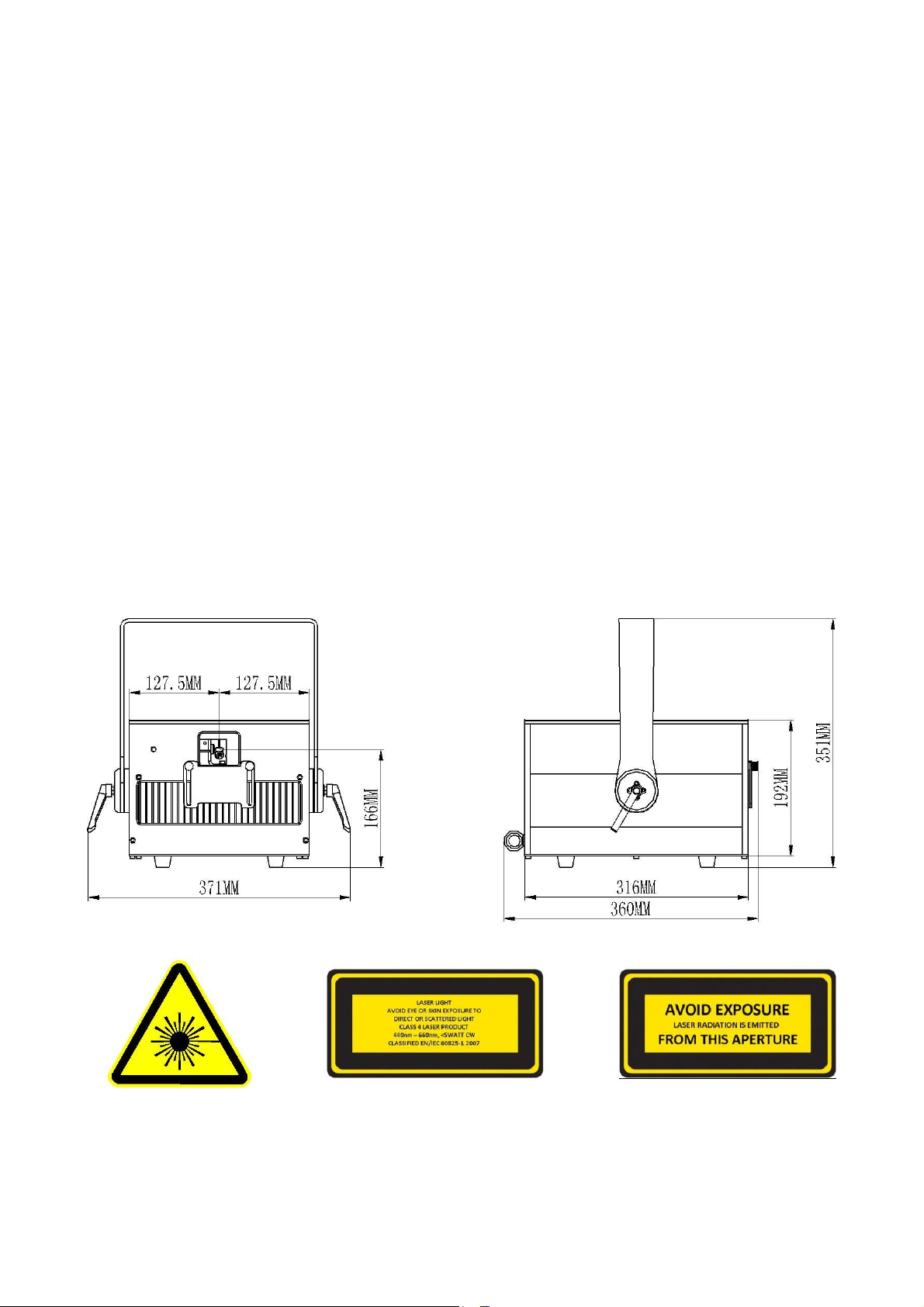
3.DIMENSIONS
All dimensions are given in millimeters
Hazard Warning Symbol Explanatory Label Aperture Label
-1-

4.SAFETY NOTES
WARNING! This projector is a Class 4 laser product. It must never be used for audience-scanning
applications. The output beam of the projector must always be at least 3 meters above the floor in the
audience. See the Proper Operation section for further information.
Please read the following notes carefully! They include important safety information about the
installation, usage, and maintenance of this product.
■Keep this User Manual for future consultation. If you sell this product to anotheruser, be sure that they
also receive this document.
■Always make sure that the voltage of the outlet to which you are connecting this product is within the
range stated on the decal or rear panel of the product.
■Product is not designed for use outdoors in adverse weather conditions. To prevent risk of fire or shock,
do not expose this product to rain or moisture.
■Always install this product in a location with adequate ventilation, at least 20 in (50 cm) from
adjacent surfaces. Be sure that no ventilation slots are blocked.
■Always disconnect this product from the power source before cleaning it or replacing the fuse.
■Make sure to replace the fuse with another of the same type and rating.
■If mounting it overhead, always secure this product to a fastening device using a safety chain or cable.
■In the event of a serious operating problem, stop using the projector immediately. Never try to repair the
unit except in a controlled environment under trained supervision. Repairs carried out by unskilled people
can lead to damage or malfunction of the unit, as well as exposure to dangerous laser light.
■Never connect this product to a dimmer pack.
■Make sure the power cord is not crimped or damaged.
■Never disconnect the power cord by pulling or any moving part. Always use the hanging/mounting bracket
or the handles. Or tugging on the cord.
■Never carry a product from the power cord.
■Always avoid eye or skin exposure to direct or scattered light from this product.
■Lasers can be hazardous and have unique safety considerations. Permanent eye injury and blindness is
possible if lasers are used incorrectly. Pay close attention to each safety REMARK and WARNING
statement in this user manual. Read all instructions carefully BEFORE operating this device.
■Never intentionally expose yourself or others to direct laser light.
■This laser product can potentially cause instant eye injury or blindness if laser light directly strikes the eyes.
■It is illegal and dangerous to shine this laser into audience areas, where the audience or other
personnel could get direct laser beams or bright reflections into their eyes.
■It is a US Federal offense to shine any laser at aircraft.
■No service allowed by customer. There are no user serviceable parts inside the unit. Do not open the
housing or attempt any repairs yourself.
Service is only to be handled by the factory or authorized factory trained technicians.
■Product is not to be modified by the customer.
■Caution use of controls or adjustments or performance of procedures other than those specified herein
may result in hazardous radiation exposure.
-2-

5.TECHNICAL SPECIFICATIONS
Laser:
Laser Classification: Class 4
Laser sources:Full diode lasers
Beam diameter (1/e2):<4.0mm
Beam divergence (1/e2):<1.0mrad (full angle)
Laser Wave Length:445-640nm
Maximum total output power:<14,000mW
Projector:
Scanner:35kpps@8°
Aperture:5mm
Scan angle:50degree,Max:70degree
Laser emission window:B+W antireflective coated
AC power input:100-240VAC / 50-60Hz
Input power:200W maximum
Max. ambient temperature:40°C
Min. ambient temperature:-5°C
Weight:15.5kg
-3-
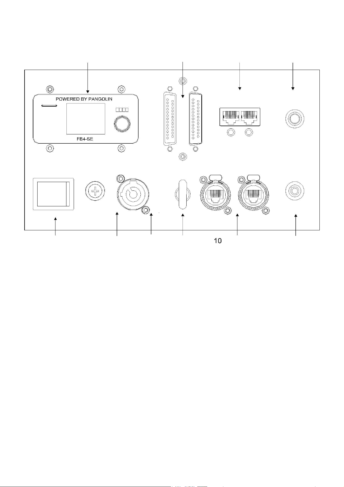
6.THE SPECIFICATION OF THE FRONT AND REAR PANEL
9876
REMOTELOCK SCAN SAFETY
POWER SWITCH
12
ETHERNET
On/Off
FUSE 6.3A
ON OFF
IN
100-240VAC
POWER
OFF ON
SECURITY
KEY SWITCH
INPUT OUTPUT
1324 5
1. ON/OFF, POWER SWITCH
2. POWER IN/OUT
3. MAIN FUSE HOLDER
4. SAFETY WIRE EYELET
5. KEY SWITCH
6. SCAN-FAIL SAFETY SWITCH
7. REMOTE LOCK (INTERLOCK)
8. ILDA IN/ILDA OUT
9. PANGOLIN FB4 SCREEN
10. FB4 INTERFAC
-4-
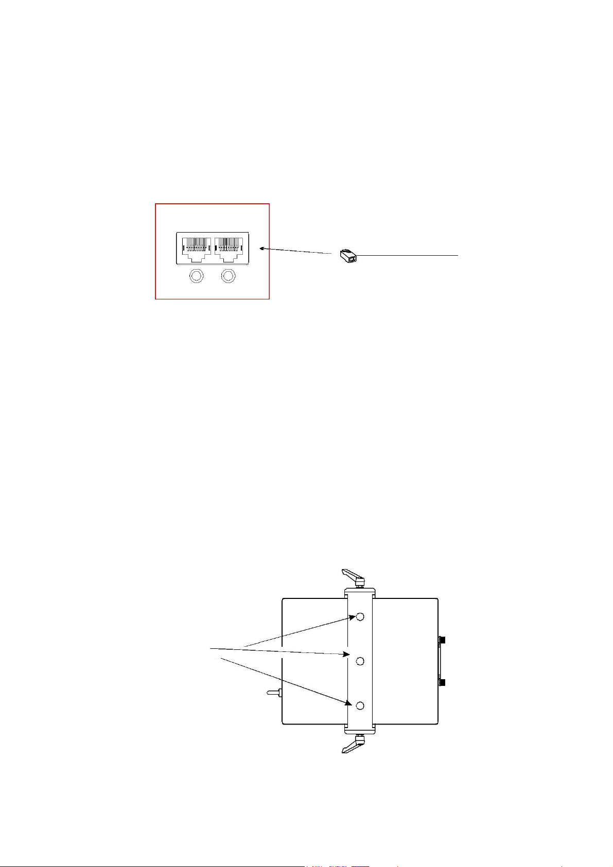
8. REMOTE INTERLOCK / REMOTE E-STOP BOX
1. If you do not use E-stop box, please insert the white RJ45 plug (shunt) to the projector.
(Refer photo below)
2. Connect the remote E-stop box to any of the RJ45 connector (Remote lock) on the rear of the
projector using Ethernet cable. Ensure that the other end of the cable is firmly attached to the E-
stop box.
REMOTELOCK
Insert the white RJ45 plug
to the projcctor
12
9.RIGGING
•Be sure that the structure onto which you are mounting this product can support its weight.
•Mount the product securely. You can do this with a screw, a nut, and a bolt. You may also use a
mounting clamp if rigging this product onto a truss. The U-shaped support bracket has three
mounting holes which may be used to secure the clamps to the projector.
•When mounting this product overhead, always use a safety cable.
• Always consider ease of access to the unit before deciding on a location for this product
15mm
-5-

10. OPERATION OF 360DEGREE BRACKET
360 degree
11. EASY BEAM ALIGNMENT MECHANISM
1. Screw bolt 1, to access the color alignment of red laser.
2. Screw bolt 2, to access the color alignment of green laser.
bolt 2
bolt 1
-6-

12.PROPER USE
This product is for overhead mounting only. For safety purposes, this projector should be mounted
on steady elevated platforms or sturdy overhead supports using suitable hanging clamps. In all
cases, you must use safety cables.
International laser safety regulations require that laser products must be operated in the fashion
illustrated below, with a minimum of 3 meters (9.8 ft) of vertical separation between the floor and
the lowest laser light vertically. Additionally, 3 meters of horizontal separation is required between
laser light and audience or other public spaces.
Projector
Beams
safety cable
3 meters
Caution –use of controls or adjustments or performance of procedures other than
those specified herein may result in hazardous radiation exposure.
-7-
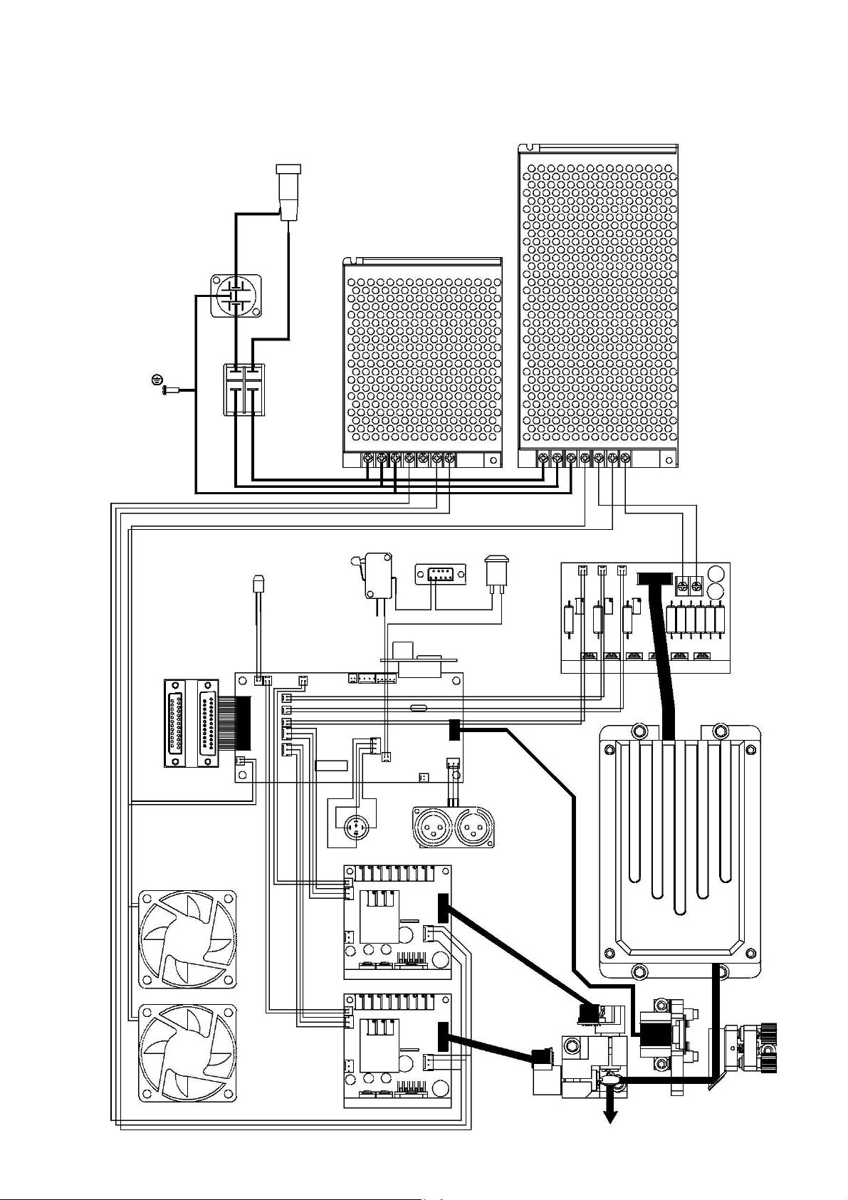
13.WIRING DIAGRAM
Fuse
Scanners
power supply(PUS)
AC110/230V NI
GND
Power Switch
-24V GND +24V
RGB Module
power supply(PUS)
0V 0V 12V12V
KeyOn/Off Switch
RGB Driver board
Interlock
RG
B
Emission LED
Auto power
+ - + - + -
cut swtich
+
-
DB-25-pin
+ -
+ -
GND
X-
Mechanical
X+
beam stop
GND
Y-
Y+
DMX
Screen lock
Fan
X Driver
Y Driver
-8-

14.ILDA CONNECTION
Connect the projector to your controller using a standard 25-pin ILDA cable (DB-25).
Be sure to tighten the connecting screws to ensure the cable does not become disconnected.
This projector is wired to accept ILDA standard analog signals for X, Y and color information.
The ILDA standard uses a DB-25 cable to carry these signals from the controller to the projector.
1
3
5
7
9
11
13
2
4
6
8
10
12
ILDA PINOUT
Pin :
Pin :
1
X+
14
X-
15
17
19
21
23
25
2
Y+
15
Y-
3
Intensity/Blanking+
16
14
16
18
20
22
24
Intensity/Blanking-
4
Interlock A
17
Interlock B
Above-DB25 male connector,viewed from front.
5
Red+
18
Red-
6
Green+
19
Green-
7
Blue+
20
Blue-
8
Deep blue+
21
Deep blue-
Below-DB25 female connector,viewed from front.
9
Yellow+
22
Yellow-
10
Cyan+
23
Cyan-
11
Z+
24
Z-
13
87 65
43
1
12
Not connected
25
Ground
12 11 10 9
2
13
Shutter
24
23
22
20
18
16
14
25
21
19
17
15
THE PROJECTORS ONLY USE THE FOLLOWING PINS:
PIN:
PIN :
1
X+
14
X-
2
Y+
15
Y-
3
Intensity/Blanking+
16
Intensity/Blanking-
4
Interlock A
17
Interlock B
5
Red+
18
Red-
6
Green+
19
Green-
7
Blue+
20
Blue-
13
Shutter
25
Ground
-9-

Table of contents


")

