Spacesaver Modular Bi-File Lateral User manual

Modular Bi-File®Lateral
Installation Instructions
920-563-6362
E-mail: ssc@spacesaver.com
Internet: www.spacesaver.com

2
Contents
Hardware Identification . . . . . . . . . . . . . . . . . . . . . . . . . . . . . . . . . .3
Pre-Installation . . . . . . . . . . . . . . . . . . . . . . . . . . . . . . . . . . . . . . . .6
Component Identification . . . . . . . . . . . . . . . . . . . . . . . . . . . . . . . .7
Installation . . . . . . . . . . . . . . . . . . . . . . . . . . . . . . . . . . . . . . . . . . .8
System Expansion . . . . . . . . . . . . . . . . . . . . . . . . . . . . . . . . . . . .20

3
Hardware Identification

4
Hardware Identification

5
Hardware Identification

6
Pre-Installation
Preparation before installation:
1. Read through the entire installation procedure before you begin this project.
2. Understand all safety statements.
3. Make sure your Modular Lateral storage system will fit within the desired location.
4. Plan to assemble the Modular Lateral system where it will be used.
5. Have the necessary tools to assemble and level the system.
Required tools:
• Power Screwdriver or Portable Hand Drill
• Phillips and Slotted Driver Bit
• 4" Long Phillips Bit
• Leveling Device (preferably a rotary laser level)
• Utility Knife
• Dead Blow Hammer or Rubber Mallet
• Hex T-Handle Wrenches: 5/32" x 6"
• Slotted Screwdriver (assorted sizes)
• Phillips Screwdriver (assorted sizes)
• Measuring Rule or Tape
• Torpedo Level
• Carpenters Level
• Apex 1/4” Square Socket
Wear eye protection and other
applicable safety equipment while
assembling your Modular Lateral
system. Know how to safely
operate the required power tools
before starting this project.
To ensure safe and easy installa-
tion, be prepared to have an addi-
tional person on-hand to assist
with certain installation steps and
lifting operations.

7
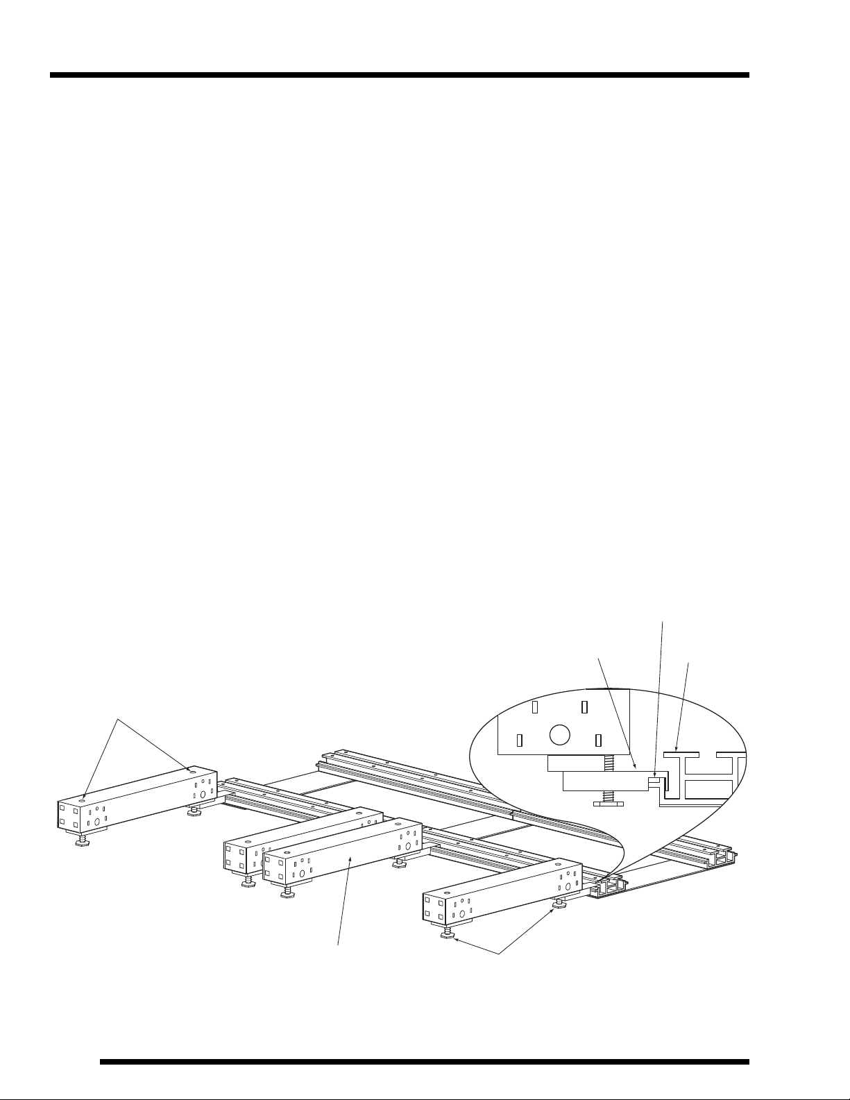
Component Identification
NOTE: The following components will be referred to in the sections to follow.
1. Aluminum extruded rail
2. Rail tie plates under the floor
3. Stationary Base
4. Rail leveler locations
5. End stop assembly locations
(2) places (In-Rail)
6. Appliance leveler
7. Stationary end piece
8. Spacer plate
9. Cover plate
10. Floor Sections
11. Splice plate (Biscuit Type) in floor
See Hardware Identification page 3
12. Ramp section
13. Tension pins
14. Tapered ramp end caps
15. Floor end cover protector
16. Center flange wheel moveable
carriage section
17. Flat wheel moveable carriage section
18. Moveable carriage side cover
19. Moveable carriage end cover
20. Stationary side cover
21. Stationary bracket. Hidden behind
cover bumper. See Hardware
Identification page 3
22. Soft cover bumper
23. Moveable bracket. Hidden behind
cover bumper. See Hardware
Identification page 3
24. Reinforcement block

88
Installation
Assembling Rail Base
1. Arrange the aluminum extruded rail (channel side down) on the floor near the final
location. Various rail lengths are provided for different system configurations. Make
sure all splices line up.
NOTE: To keep the rail assembly square, loosely install all self-tapping screws. Once
alignment is confirmed, tighten screws in a random sequence.
2. Fasten rail tie plates (countersunk holes facing out) to the bottom side of the alu-
minum rail using self-tapping screws. Universal tie plates are used at both ends of
the rail assembly and at all rail splices. All sixteen countersunk holes will be used to
attach rail splices, eight self-tapping screws per rail. Tie plates are shifted inward
when used at rail ends, only eight self-tapping screws will be required.
x 16
x 8
x 8
Universal Tie Plate (2)
960181.001
Self-tapping screw
#10-32 x1/2"
Aluminum extruded rail (1)

9
Installation
9
Locating and Leveling Rail Base
1. Position rail channel side up in the final location. If installing the unit against a wall,
place the rail assembly 2-1/2” plus the depth dimension of the stationary base away
from the back wall.
2. Insert leveling screws at each rail leveler location. Use a 5/32” allen wrench to turn
each leveler, until it touches the floor below.
NOTE: A laser type level is recommended for the next step but not required.
3. Use the level to determine the highest point on the floor. Spot check along each rail,
over the entire footprint of the rail assembly. If the high point is under a splice plate,
raise the rail assembly to create a 1/8” space between the tie plate and the floor. A
1/4” space between the tie plate and the floor is required if the high point is located
anywhere else.
NOTE: If the unit will be expanded in the future, check for a higher point in the expansion
area. If found, set the rail assembly 1/4” above the expansion area high point.
990036.002
Socket Head
Leveling Setscrew
Half Dog Point
5/16" - 18 x 1-1/2" (4)
Wall cross-section
2-1/2"
+
Depth of
Stationary Base
Floor cross-section
1010
Installation
Leveling Stationary Bases
1. Position a stationary base over the edge of the back rail assembly. The stationary
base has a notched spacer channel that will mate with the rail edge.
NOTE: The appliance leveler is completely raised in the stationary base at this point.
NOTE: Use a 1/4” square Apex socket to adjust the appliance leveler.
2. Adjust the appliance leveler closest to the rail until the notch from the spacer channel
begins to lift off the rail.
3. Place a torpedo level on the stationary base section and raise the opposite end until
level.
4. Repeat steps 1, 2, and 3 with each stationary base section, distributing them along
the rail near their final location.
Adjusting Leveler
Location
Stationary Base (3) 960210.001
Appliance Leveler (6)
3/8 - 16 x 2-1/4"
Back Rail
Notched
Spacer Channel
Stationary Base (3)

11
Installation
11
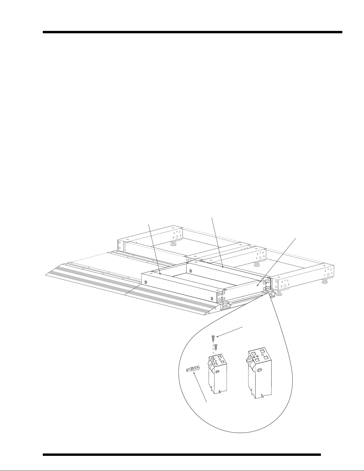
Assembling Stationary Bases
NOTE: A specially designed tab and hole interlocking system is used to attach many of
the following pieces. Use a rubber or dead blow mallet to assemble.
1. Using the interlocking system, attach a stationary end piece with two of the previously
installed stationary bases. Tap into place with a rubber or dead blow mallet.
2. With all stationary bases assembled, set one stationary base end 1-9/16” from the rail
end.
3. Connect stationary bases using a optional spacer plate and the interlocking system.
Tap into place using a rubber or dead blow mallet.
4. Set the cover plate between the stationary base and rail assembly. Using self-tapping
screws, fasten the cover plate to the stationary base spacer channel.
960180.001
Self-Tapping Screw
#10-32 x 1/2"
Stationary Base End (7)
Spacer Plate (8)
1-9/16"
Cover Plate (9)
Interlocking System
Tab
Hole
12
Installation
12
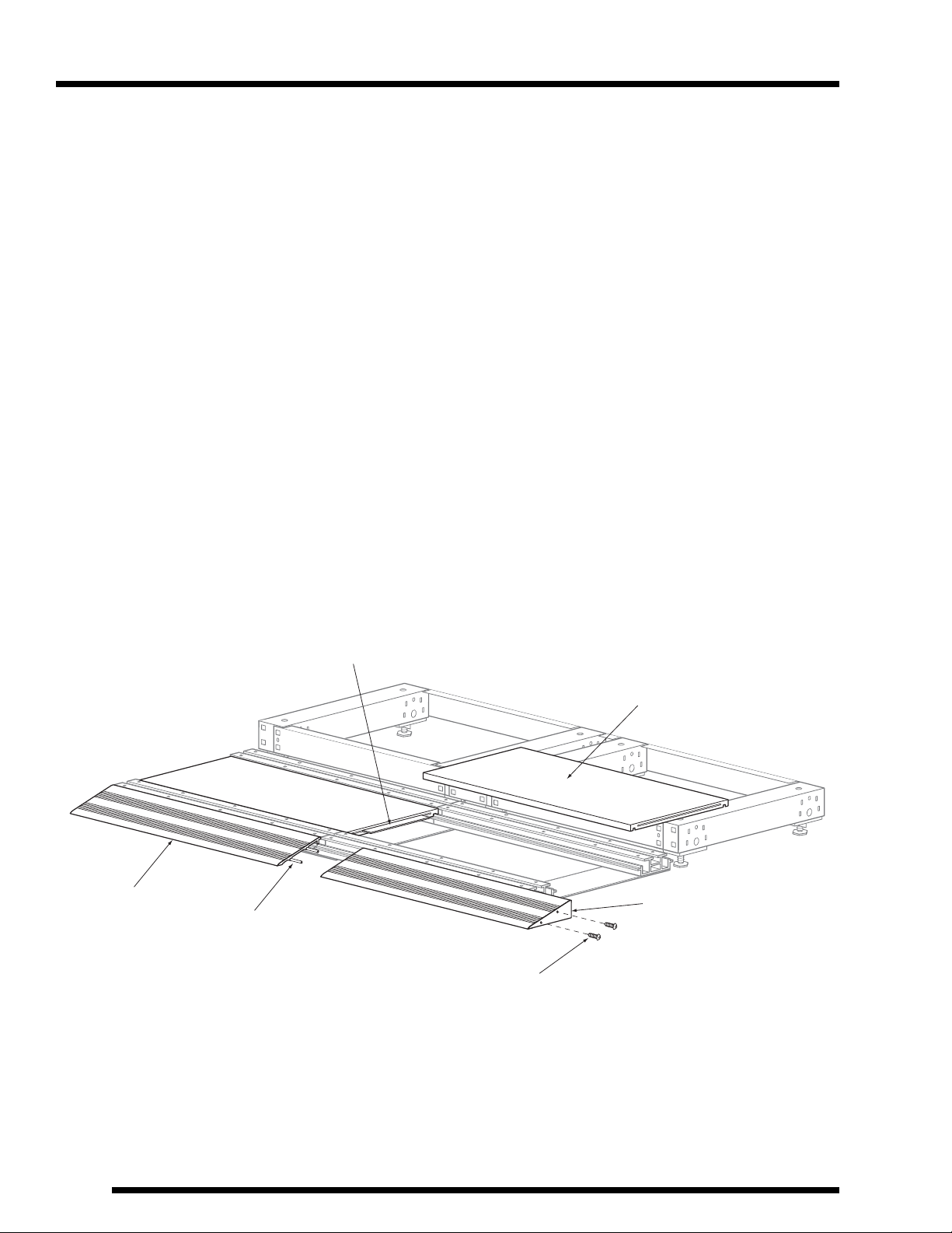
Assembling Floor and Ramp
1. Insert floor sections between the assembled rails. The under side of each floor sec-
tion has a routed slot that attaches to a formed rail. A slot is also routed across the
end of each floor section. Tap a biscuit type splice plate into the center of each slot.
The next floor section will share this splice plate producing a stabilized joint between
floor sections.
2. Use a rubber or dead blow mallet to avoid damage to the floor sections. Tap the end
floor section until it is aligned with the end of the rail assembly.
3. Slide ramp section from the side onto the front rail. If space does not permit, floor
section may be raised slightly allowing the ramp to slip into place from the front.
4. Ramp sections are held together at the splice using two tension pins. Tap each pin
about half way into one ramp. Engage the next ramp section and tap the joint closed.
5. Fasten ramp end caps with sheet metal screws using the same openings as the ten-
sion pins.
96002.02
Sheet Metal Screw
Pan Head Phillips
#6 x 3/4"
91011.02
Tension Pin (13)
Floor Section (10)
38199.01
Biscuit Type Splice Plate (11)
1/8 x 3/4 x 6"
Ramp End Cap (14)
Ramp (12)
13
Installation
13
Assembling Moveable Carriage
NOTE: The reinforcement block is attached to the first and last moveable carriages only,
located on the extreme left and right of the moveable carriages directly over the
back rail. The reinforcement block serves as part of the In-Rail end stop.
1. Install the reinforcement block to the movable carriage section with the center flange
wheel using a machine screw.
2. Place the moveable carriage section with the flat wheel on the front rail closest to the
ramp.
3. Place the moveable carriage section with center flanged wheel and reinforcement
block, previously installed on the back rail, closest to the stationary bases. Center
wheel flange and reinforcement block will rest in the rail slot groove.
4. Using the interlocking system, attach side cover to the moveable carriage sections.
Repeat on opposite side.
Moveable Carrige
Side Cover (18)
Moveable Carrige Section
w/Center Flange Wheel (16)
Moveable Carrige Section
w/Flat Wheel (17)
96023.01
Flat Head Phillips
#8 - 32 x 1/2"
550392.001
Reinforcement Block (24)

14
Installation
14
Assembling Moveable Carriage (continued)
5. Moveable end covers are attached to each moveable carriage to cover the wheel
mechanism. Interlock one end in place and use a slotted screwdriver to slightly pry
the other end into place. Once aligned with the holes, tap the cover into place using a
rubber or dead blow mallet.
NOTE: Hardware field assembly is required for end stop installation. See Hardware
Identification page 3.
6. The In-Rail end stop assembly slides into the rail end cavity and is secured into place
by turning the setscrew. Set the end stop so the moveable carriage end is in align-
ment with the stationary bases end upon stopping. Repeat steps 5 & 6 for the move-
able carriage on the opposite end.
NOTE: This installation sequence does not cover assembling the shelving. For detail on
shelving see OP-0039 “4-Post and CASE Style Shelving Installation.”
Moveable Carriage
End Cover (19)
End Stop Assembly (5)
(Field Assembled)
(93017.01 and 99026.01)
Tighten to
secure In-Rail
End Stop

15
Installation
15
Assembling Stationary Shelving
1. Set shelving on top of the stationary bases. Attach the stationary side cover by inter-
locking one end in place and use a slotted screwdriver to slightly pry the other end in
to place. Once aligned with the holes, tap the cover in place using a rubber or dead
blow mallet.
NOTE: The stationary side cover prevents the shelving from moving side to side.
2. The optional filler channel must be bent 90° degrees. The long side of the filler chan-
nel fits between the stationary shelving sections at the front. The short side of the
channel fits between the stationary shelving sections across the top. Always align the
channel with the top of the shelving. The channel may have to be trimmed on the
long side for special height shelving.
3. Attach a filler channel between each static section of shelving. Fasten filler channel in
three locations on each side of shelving and twice at the top side using Tek screws.
4. Attach the stationary bracket to hold the shelving in place from front to back. Fasten
one bracket on each side of the stationary base using pan head screws.
Stationary
Side Cover (20)
Filler Channel
Stationary
Shelving
Stationary
Bracket (21)
550366.001
96116.02
#10-24 x 1/2"
Pan Head
Phillips
960216.001
#10 x 5/8"
Hex Head
Tek Screw
Located inside
Stationary Shelving

16
Installation
16
Assembling Stationary Shelving (continued)
5. Secure the shelving in place using Tek screws at each bracket location.
6. Place the soft cover bumper over the stationary bracket rivet and slide down into
place. Secure cover at the bottom using pan head screw.
7. Secure the shelving to the stationary base at each rear corner using Tek screws.
NOTE: Floor end cover protectors are specific to the right and left floor sides.
8. Fasten the center of the floor end cover protector to the floor section with a wood
screw. Secure floor end cover to rail assembly using self-tapping screws at the four
outside holes of the floor end cover. Check the fit. Repeat on opposite side.
Stationary
Bracket (21)
550366.001
960216.001
#10 x 5/8"
Hex Head
Tek Screw
960216.001
#10 x 5/8"
Hex Head
Tek Screw
Soft Cover
Bumper (22)
96116.02
#10-24 x 1/2"
Pan Head
Phillips
Floor End
Cover Protector (15)
960180.001
Self-Tapping Screw
#10-32 x 1/2"
96047.02
Wood Screw
Pan Head Phillips
#8 x 3/4"

17
Installation
17
Assembling Moveable Carriage Bracket
NOTE: Each moveable carriage requires two stationary brackets and two moveable
brackets. All four corners of a moveable carriage will require brackets. The sta-
tionary brackets prevent the shelving from moving side to side and serve as an
In-Rail anti-tip device.
1. Slide the moveable bracket into the rail groove, turn it 90° degrees and then fasten
it to the center flange wheel section using pan head screws. Fasten the stationary
bracket using a pan head screw. Repeat on opposite side.
2. Secure the shelving using Tek screw at one of the top two holes in the stationary
and moveable brackets.
3. Attach the soft cover bumper over the stationary bracket rivet and then slide down
into place. Use a pan head screw to fasten the cover at the bottom.
Stationary
Bracket
(21)
550366.001
960216.001
#10 x 5/8"
Hex Head
Tek Screw
96116.02
#10-24 x 1/2"
Pan Head
Phillips
Soft Cover
Bumper (22)
Moveable
Bracket (23)
550363.001
960216.001
#10 x 5/8"
Hex Head
Tek Screw
Moveable Shelving
Step 1
Step 2

18
Installation
Assembling Bi-File®and Tri-File®Overhead Anti-Tip
NOTE: Angle brackets and field assembled hardware from page 4 (Bi-File®) and 5 (Tri-
File®) are installed as part of an overhead anti-tip device. When moveable shelving
reaches a certain height an overhead Anti-tip device must be incorporated. The
field assembled bracket bridges the space between the moveable shelving carriage
and the stationary shelving.
1. Using Stationary Hardware from page 4, attach angle brackets to an open channel
section designed to accommodate both Bi-File®and Tri-File®overhead anti-tip sys-
tems. The opening in the angle bracket is slotted for adjustment.
2. The channel and bracket assembly attaches to the shelving by sliding into the open-
ing at the top of the shelving upright. The lower side of the channel always faces
front.
3. Once the brackets are fully seated into the shelving uprights, secure them into place.
Each bracket contains multiple threaded screw holes. Select the hole which lines up
nearest the bottom of the upright keyhole and fasten at this location with a pan head
screw and washer.
95016.03
Carriage Bolt
#1/4-20 x 1/2"
Angle Bracket
401198-001 Open Channel
Section
94017.05
1/4" Washer
93015.02
Keps Nut
1/4-20
96004.02
Pan Head Phillips
#10-32 x 3/8"
94017.03
#10 Flat Washer

19
Installation
Assembling Bi-File®and Tri-file®Overhead Anti-Tip (continued)
4. The field assembled anti-tip (angle bracket with bearing) is attached to the moveable
shelving carriage in similar fashion as in the previous three steps. Align the bracket
and roller guide as shown below.
5. The Tri-File®field assembled anti-tip hardware detailed on Page 5 is attached in the
same way as steps 2-4. Orient the bracket and roller guide as shown below.
Bi-File
Feild Assembled
Anti-Tip Hook
Assembly
Tri-File
Feild Assembled
Anti-Tip Hook
Assembly
96004.02
Pan Head Phillips
#10-32 x 3/8"
94017.03
#10 Flat Washer

20
System Expansion
20
Expansion installation
NOTE: The following information deals only with the additional steps required for adding
moveable carriages to either the length or depth of an existing system. Customers
may expand their systems in either way. A basic Bi-File® system will begin with two
stationary bases and one moveable carriage. This system may be expanded to
any practical length, as long as there is one fewer moveable carriages than station-
ary bases. Systems are also available in a Tri-File® configuration. Tri-File®places
an additional rail assembly and row of moveable carriages in front of the existing
Bi-File®.
NOTE: The universal strap shown is used in a variety of different applications.
Expanding Bi-File®Length
1. Assemble the rail expansion sections to be used. Refer back to Rail Assembly, pages
8 & 9.
2. Place two universal straps as shown. Align expansion rail and existing rail assemblies
so that the ends butt up next to each other. Fasten them to the end of the existing rail
assembly using self-tapping screws.
3. Elevate the Bi-File® rail assembly to match the existing rails. Placing a carpenters
level across both rail assemblies, level the expansion rails to the same elevation as
the existing rail assemblies.
Existing Rail
Expansion Rail
Universal Strap
960180.007
Self-Tapping Screw
#10 x 3/8"
Table of contents
Other Spacesaver Indoor Furnishing manuals

 Assembly instructions")


