Sparta CENTURY Series User manual


www.SteamPoweredRadio.Com
TECHNICAL
MANUAL
CENTURY
SERIES
Models 4510, 45·
15
,
4520
and
4525
Tape Cartridge Reproducers
PROPRIETARY
NOTI
CE
Sparta Electronic
Corpor
ation
proprietary
data
is
contained
herein.
Neither
this
document
nor
the
information
contained herein shall be disclosed
to
others
for
manufacturing
or
any
other
purpose except
as
authorized in
writing
by
Sparta Electronic Corporation.
~1973
098-4510
$5.00
~
;g[p~~lf~
~
ELECTRONIC
CORPORATION
!5851
FLORIN·PERKINS
ROAD
SACRAMENTO,
CALIFORNIA
9582
8
A
DIVISIO
N
or
COM
P
UTE
R EQ
UI
PM
ENT
CORPORA
TIO
N

www.SteamPoweredRadio.Com
I . . . .
\ ·..
.
Dear
Customer:-
.
,
Careful
attcnt1011
to
Qu::ility
Control
is
another
important
clement
in
our
daily
effort
to
provide
y
ou.
vilh
excellence
of
product
and
service.
At
SPARTA
each
piece
of
equipment
and
sub-assembly
:receives
numerous
insp
e
ctions
and
tests
in
the
process
of
production.
The
final
results
·must
mcastirc
·
within
our
ex.acting
requi
re
ments
before
it
is
shipped
to
you.
Listed
bclo,~
are
just
a
few
of
the
major-
;:c
heck
points
am!
tests
this
partic\1br
piece
of
equipment
has
received
before
being
prepared
for
shi7)·· .
;:.:
ncnt.
Should
you
note
any
discrep
an
cy
in
the
appearance
or
operation
of
your
SPARTA
Product
or
if
yo
:h
ave
any
general
comments
as
to
how
we
might
be
of
greater
service.
your
sugge
_
stions
will
be
greatly
:a
ppreciated..
. · .
.
.
..
CENTURY
SERIES .
..
MODEL
NO:
._f'~/~ - .
:PURCHASER .
l(e.4~
.
----
.
__
·.
_DATE:
_±~
-~/ -
-
7
✓
- -
- -
-
_
:S
ERIAL
NO..
//73
CALID.
BY
~-
~
--
_:__
•
____________
✓
_
-
_Intc.mal
Mech.
&
Soldering
···-
-
~·
--·
.·.
.
..
.
FREQ:
RESPONSE
v
Mech.
oper?,tion
&
Press
Roller
Adj.
MONO LEF'T
CHA
NN
EL
--------------
v
Fuce
&
Power
Supply
Volt
ag
e
(Playback)·
-------------,-
.
50Hz
-~S--
db
75Hz
1J
db
150
Hz
+, b
db
✓
Azimuth
Adj.
(Play
Back)
--------------
v-
Equalization
set
(Play
back)-
··
· •·
,....
IL__
...,__~
t;J
- ~
--d-b_m_R
__
_
___
_
dbrn.
Output
!-evcl
(600
ohms)'
•_·
~L
__:S--6
'JJt!5,
R
Si
g
nal/Noise
.
.
-··
ow
&
Flutter--
·
_:
;··
·-
LL~
w
.
✓
c
✓
T
ue
Amp.
Sensitivity
.:-.
one
Output
· · ·• ·
;:
✓
R
emote
Contr
ol
Start
&
Stop
-:..
✓
.
15
0
Hz
. .
End
.
of
M
es
sa
ge
&J
nd.
Lamp
•
use+
Power
Su
pp
ly
Voltage
(Record)
-
as
Trap
Adj.
(Record)
'
as
Trap
Adj.
fCµe
) _.,
_':·.:
- . : ·
.......-
F
✓
Bi
v
Bi
......--
Bi
as
·Curr\.;nt
Adj.
(Rc~ord)
1,.,-""'
Bi
as
Current
Adj.
(Cue)
V A
300
Hz =
4.00
Hz
~
600
Hz
-,
£
. l
KHz
szS
db
db
·
db
db
_
2.
5
KHz
-b
<t-
db
5KHz
*db
8'KHz
: db
. lC ,
KHz
db
12
KHz_---'---
__
db
15
KHz
-,
/,
db
RIGHT CBANNE L
STE
lfEO-
vE
t,A
zimuth
Adj.
(Record)
quaHzation
(Record)
·
·.
f
udio
Current
VU
Meter
Calib~
·
.·
· . · S0I·Iz
db
A.
__._
.
:
.
......
J.
.J'7D
v-f'.>
i
st.
Total
System
.
,
·V B
~
C
S"IK
~ -
..
..
. ·
.
Stereo
Un-its
fi}IJ
I "
.
,:
. . . • .
.
£...---"
150
Aux.
Cue
(Record)
emote
Control
.
0{
v1
n
put
Source-
--
.
'
IC:-
~
.,c_
Encoder
R/PB
Crosstalk
Cuc
to
Prog
Meter
Cal:
l·KHz
150
Hz
Bias
R
un
In
.
Channel
Separation
Plwsing
_
..
.
----'l<----
75Hz .
db
-------
. 150Hz
db
--
300
Hz
db
400
Hz
·
db
600.Hz
db
1
KHz
db
2. 5
KHz
db
S KHz dh
8 KHz db
10
KHz
db
~
12
KHz
db
-------
. 15
KHz
clb
..
..

www.SteamPoweredRadio.Com
•
CONTENTS
CENTURY
SERIES
FEATURES
INTRODUCTION ................................
GENERAL
DESCRIPTION ........................ 1
3
SPE
CI
FICATIONS . . . . . . . . . . . . . . . . . . . . . . . . . . . . . . . . 5
INSTALLATION
UNPACKING
ENCLOSURES
•••••••••••••••••••••••••••
0
•••••••
AUDIO &
CONTROL
CONNECTIONS
OPERATION
••••••••••••••••••••••
0
••
CARTRIDGE INSERTION
READY INDICATION ..............................
CARTRIDGE PLAY
CARTRIDGE
STOP
..............................
6
6
7
8
8
8
8
CARTRIDGE
RELEASE
• • • • • • • • • • • • • • • • • • • • • • • • • • •• 9
E.
0.
M. INDICATION ............................ 9

www.SteamPoweredRadio.Com
ELECTRONIC ADJUSTMENTS
AUDIO
LEVEL
. . . . . . . . . . . . . . . . . . . . . . . . . . . . . . . . 10
EQUALIZATION . . . . . . . . . . . . . . . . . . . . . . . . . . . . . . . 10
STOP TONE
SENSITIVITY.....
• • . • • • • • • • • • • • • • . • 10
E.
0.
M.
TONE SENSITIVITY • • • • • • • • • • • • • • • • • • • • 11
MECHANICAL ADJUSTMENTS
(See
Figure
1)
SOLENOID
POSITION..........................
12
PINCH
ROLLER PRESSURE • • • • • • • • • • • • • . • • • • • • • • 12
CARTRIDGE
RELEASE
• • • • • • • . • • • • • • • • • • • • • • • • • • 12
ARMATURE
RETURN STOP • • • • • • • • • • • • • • • • • • • • • • 13
ROTARY
LIFT MECHANISM • • • • • • • • . • • • • • • • • • • • • 13
FLYWHEEL THRUST BEARING • • • • • • • • • • • • • • • • • • • 13
FIG
URE
1 - UPPER VIEW MECHANISM • • • • • • • • • • • 14
SOLENOID ASSEMBLY DRAWING
(P-3
8)
• • • • • • • • • • 14 a
REPLACEMENT & ALIGNMENT OF
TAPE
HEADS
(See
drawing
P-120487)
TRACK
CONFIGURATION.......................
15
HEAD
LOCATION..................
.
...........
15
TRUE
TANGENT.. . . . . . . . . . . . . . . . . . . . . . . . . . . . . . 15
HEAD REPLACEMENT • • • • • • • • • • • • • • • • • • • • • • • • • • 16
HEIGHT ADJUSTMENT • • • . • • • • • • • • • • • • • • • • • • • • • 16
ZENITH ADJUSTMENT • • • • • . • • • • • • • • • • • • • • • • • • • 17
AZIMUTH ADJUSTMENT. • • • • • • • • • . • • • • • • • • • • • • • 17

www.SteamPoweredRadio.Com
.,..
RECORD HEAD ALIGNMENT • • • • • • • • • • • • • • • • • • • • • • •
17
STEREO
HEAD ALIGNMENT • • • • • • • • • • • • • • • • • • • • • • • 18
STEREO
CARTRIOOE CONSIDERATIONS
21
MAINTENANCE
CLEANING ......................................
22
HEAD DEMAGNETIZING • •• • •• • • • • • • • • • • • •• • • ••• • • 22
CARTRI.D(;E CARE
•••••......•.•.•.•.•••••.••.....
22
BELT
CHANGE • • • • . • • • . . . . . . . • . • • • • . . . • • . . . . • . • . 23
CIRCUIT DESCRIPTIONS
POWER SUPPLIES (See
drawing
S-154)
• • • • • • • • • • • • • • 24
CONTROL CIRCUIT (See
drawing
S-150)
• • • • • • • • • • • • • 25
CUE TONE
DETECTORS
(See
drawing
S-156).........
26
CUE LOCKOUT (See
drawing
S-150
&
S-156)
PROORAM AMPLIFIER (See
drawing
S-157)
WARRANTY
SCHEMATICS
S-154
POWER SUPPLIES
S-150
CONTROL CIRCUIT
S-156
CUE TONE
DETECTORS
S-157
PROORAM AMPLIFIER
P-34
INTERCONNECTING DIAGRAM
•••••
0
•••
27
28

www.SteamPoweredRadio.Com
INTRODUCTION
The
Century
Series
of
cartridge
reproducers
are
intended
for
broadcast
and
industrial
applications
requiring
continuous
duty
capability
and
highest
quality
performance.
Each
model
meets
or
exceeds
all
applicable
NPiB
Standards.
The
Century
Series
tape
transport
has
been
specifically
designed
to
accept
the
NAB
Type
A
(Model
300)
cartridges,
and
delivers
optimum
performance
with
loads
of
up
to
10
1/2
minutes
of
lubricated
tape.
Monaural
reproducers
use
a
standard
_2
track,
single
head
configuration,
with
the
program
amplifier
connected
to
the
upper
track,
and
the
cue
amplifier
connected
to
the
lower
track.
Stereo
reproducers
use
the
NAB
standard
3
track
head.
The
top
track
is
the
left
program
channel;
the
lower
track
is
for
cue
tones.
In
the
recording
process,
a
1000
Hz
(cycles
per
second)
tone,
of
about
1
second
duration,
is
automatically
recorded
on
the
cue
track
each
time
the
cartridge
transport
is
started
in
the
record
mode.
Each
reproducer
is
furnished
with
a
detector
circuit
which
responds
to
this
tone
by
stopping
the
transport.
This
cues
the
cartridge
to
the
beginning
of
the
announcement.
The
1000
Hz
toPe
is
called
the
primary
cue
tone.
Models
4515
and
4525
have
an
additional
detector
circuit
which
responds
to
the
secondary
cue
tone
frequency
of
150
Hz.
This
tone
is
popularly
called
the
E.
0.
M.
tone,
standing
for
"end-of-message",
and
is
used
in
automation
and
for
other
control
or
signaling
functions.
When
a
150
Hz
tone
is
detected,
a
relay
contact
closure
is
connected
to
terminals
at
the
rear
of
the
reproducer
-(1)

www.SteamPoweredRadio.Com
chassis.
This
signal
can
be
used
to
advance
an
automation
syst
e m
to
the
next
"event"
or
turn
on
a
light
in
a
nearby
studio
as
a
signal
to
an
announcer
to
begin
speaking
etc.
On
Century
Series
Recorders,
the
E.O.M.
tone
can
be
put
on
the
cue
track
during
either
play
or
record
conditions,
making
it
possible
to
audition
a
cartridge
before
placing
the
tone
on
the
cue
track.
Several
mounting
configurations
are
available
for
Century
Series
equipm
e
nt:
Single
table
top,
with
flip
top
cover
Dual
table
top,
with
flip
top
cover
Triple
rack
mount,
with
panel
lock
screws.
Quad
custom
cabinet,
with
walnut
grain
finish.
Bottom
plates
with
no-mar
rubber
feet
are
provided
with
table-top
configurati
o
ns,
and
must
be
removed
for
use
in
the
triple
rack
mount
or
quad
cabinet.
Each
module
can
slide
forward
in
the
rack
mount
and
quad
cabinet
for
convenient
access
to
all
adjustments
and
for
head
cleaning.
Additionally,
the
rack
mount
has
front
panel
lock
screws
to
secure
the
modules,
and
removable
tabs
on
the
rear
of'
the
p.
c.
board
covers,
to
prevent
the
modules
from
being
inadvertently
removed
from
the
rack.
Record
modules
are
the
same
size
as
the
reproducer
modules
and
can
mount
in
any
of
the
multiple
module
housings.
When
a
record
module
is
used,
it
is
attached
to
the
right
side
of
a
reproducer
module
(as
viewed
from
the
front)
with
hardware
provided,
and
the
two
modules
slide
in
and
out
of
their
housing
as
one
unit.
(2)

www.SteamPoweredRadio.Com
GENERAL
DESCRIPTION
Four
basic
models
are
available:
4510
-mono
reproducer,
with
standard
1
kHz
stop
tone
detector.
4515
-mono
re
producer,
with
added
150
Hz
EOM
tone
detector.
4520
-
stereo
reproducer,
with
standard
1
kHz
stop
tone
detector.
4525
-
stereo
reproducer,
with
added
150
Hz
EOM
tone
detector.
All
electronics
for
audio
reproduction
and
tone
detection
are
on
a
single
plug-in
printed
circuit
board,
as
is
the
power
supply
regulator.
Thus,
each
model
uses
the
same
basic
p.c.
board,
less
unneeded
circuit
components.
All
electronic
adjustments
are
accessible
through
the
p.
c.
board
cover.
Integrated
circuits
have
been
used
in
both
the
program
and
cue
amplifiers,
to
provide
best
performance,
while
minimizing
the
number
of
components
required.
The
IC's
are
interchangeable
between
all
circuits
and
are
plug-in,
for
ease
of
trouble
shooting
in
case
of
a
malfunction.
A 1700 rpm
hysteresis
syncronous
motor
is
utilized
in
Century
Series
reproducers,
and
runs
only
when
a
cartridge
is
inserted.
The
inherently
smoother
high
speed
motor
is
coupled
to
the
flywheel-driven
capstan
via
dual
flutter-filter
belts,
resulting
in
unsurpassed
flutter
and
wow
characteristics,
plus
cool-running
operation.
Monaural
reproducers
can
be
field-converted
to
stereo
operation,
if
desired.
All
units
are
wired
for
stereo
operation,
and
require
only
the
stereo
p.c.
board,
stereo
head,
an
additional
output
transformer,
and
a 2
channel
LCR
to
replace
the
single
channel
LCR
used
for
audio
switching.
(3)

www.SteamPoweredRadio.Com
Each
reproducer
is
also
factory
wired
for
later
connection
to
a
record
module,
in
case
additional
record
capacity
is
required.
The
price
of
the
record
module
includes
a
record
head
and
head
mount.
The
record
modules
are
available
in
four
basic
models.
4710
-
mono
record,
with
standard
1000
Hz
stop
tone
generator.
471
S -
mono
record,
with
added
1
SO
Hz
EOM
tone
generator
4720 -
stareo
record,
with
standard
1000
Hz
stop
tone
generator.
4725
-
stereo
record,
with
added
150
Hz
EOM
tone
generator.
Remote
Control
of
start/stop
functions
is
available
on
the
barrier
strip
at
the
rear
of
each
reproducer
module.
Audio
outputs
are
also
taken
from
the
barrier
strip.
Additionally,
an
amplified
cue
channel
output
is
provided,
which
can
be
used
to
check
cue
tones,
as
well
as
connect
to
an
automatic
logging
system
for
automation
applications.
If
the
optional
150
Hz
EOM
tone
detector
is
included,
its
contact
closure
appears
at
barrier
strip
terminals
also.
(4)

www.SteamPoweredRadio.Com
Frequency
Response:
Noise:
Distortion:
Wow
&
Flutter:
Equalization:
Audio Output:
Cue
Signals:
Tape
Speed:
Playing
Time:
Remote
Control:
Mounting:
Dimensions:
Power:
Weight:
SPECIFICATIOl'S
50-15,
000
Hz±
2db
55db
or
more
below
saturation
recording
(mono)
52db
or
more
below
saturation
recording
(stereo)
2%
or
less
0.2%
or
less
NAB
(adjustable)
600
ohms
balanced,
+6
dbm
nominal,
+16
dbm
maximum
NAB
primary
cue
(stop) l KHz
standard;
second
-
·
ary
cue
(EOM) 150 Hz
optional;
EOM
signal
provided
as
Form
A
contact
closure.
(5)
7.
5
ips;
shielded
hysteresis
synchronous
motor;
non-magnetic
dynamically
balanced
flywheel;
multiple
belt
flutter-filter
drive
system.
2
seconds
to
10-1/2
minutes,
NAB
size
A
cartridge
All
functions
available
Single
desk,
dual
desk,
7"
rack
mount
adaptor
for
3
modules,
custom
walnut
grain
cabinet
for
4
modules
(15" H x
14"
W x 15
1/2"
D)
Playback
module
and
record
amplifier
module
each
6"
H x
5-3/4"
W x
14"
D
117
volts,
60Hz
(available
for
other
power
line
standards
on
special
order)
16
lbs,
including
lid
www.SteamPoweredRadio.Com
INSTALIATION
UNPACKING:
After
removing
the
equipment
from
the
shipping
container,
carefully
inspect
it
for
shipping
damage.
If
damage
is
discovered,
make
a
written
request
to
the
carrier
for
inspection,
and
retain
all
cartons
and
fillers.
The
carrier
is
responsible
for
any
damage
incurred
in
shipping,
but
the
claim
must
be
promptly
filed
by
the
receiver.
ENCLOSURES:
Table
top
units
are
shipped
with
lids
installed.
fiowever,
Triple
Rack
Mounts
and
Quad
Cabinets
are
shipped
separately
from
the
transport
modules.
The
modules
slide
in
from
the
front,
and
in
the
Triple
Rack
Mount
can
be
fastened
in
place
by
turning
the
front
panel
lock
screws
clockwise.
There
is
a
tab
on
the
rear
of
the
p.
c.
board
cover
on
rack
mounted
units
which
can
be
turned
upward
to
prevent
accidental
removal.
( 6)
www.SteamPoweredRadio.Com
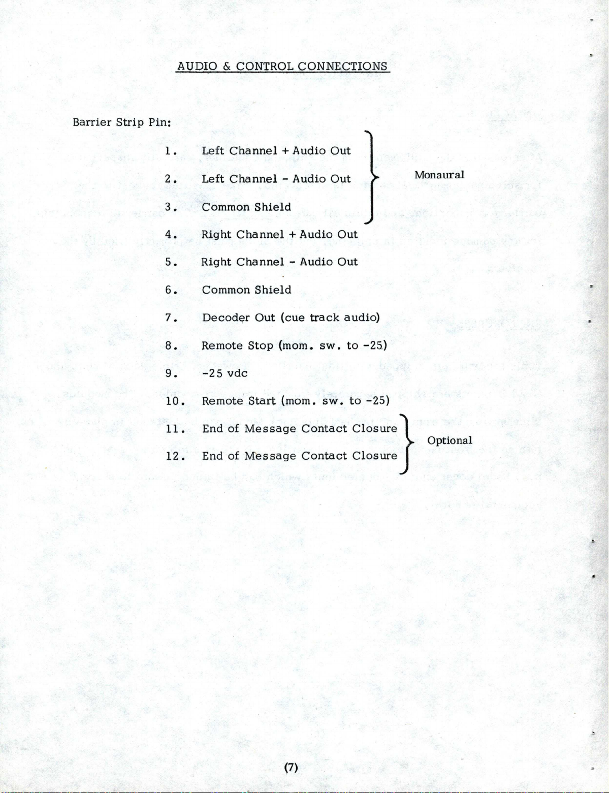
AUDIO & CONTROL
CONNECTIONS
Barrier
Strip
Pin:
1.
Left
Channel
+
Audio
Out
2.
Left
Channel
-
Audio
Out
Monaural
3.
Common
Shield
4.
Right
Channel
+
Audio
Out
5.
Right
Channel
-
Audio
Out
6.
Common
Shield
7.
Decod~r
Out
(cue
track
audio)
8.
Remote
Stop
(mom.
sw.
to
-25
.) ·
9.
-2
5
vdc
10.
Remote
Start
(mom.
sw.
to
-25)
End
of
Message
Contact
Closure}
Optional
End
of
Message
Contact
Closure
12.
(7)
www.SteamPoweredRadio.Com
CARTRIDGE
INSERTION:
READY
INDICATION:
CARTRIDGE Pl.A
Y:
CARTRIDGE
STOP:
OPERATION
The
cartridge
should
be
inserted
firmly
so
as
to
bring
the
pinch
roller
fully
into
position.
The
cartridge
pushes
the
contact
arm
only
about
3/8"
and
this
limited
motion
is
translated
into
nearly
90
degrees
rotation
of
the
pinch
roller
shaft,
thus
a
certain
amount
of
force
is
required.
When
a
cartridge
is
inserted
the
Touchbar
glows
red
on
the
left
side,
indicating
a
"ready"
condition.
The
motor
starts
when
the
cartridge
is
inserted
and
requires
approximately
2
1/2
seconds
to
reach
operating
speed.
Depress
the
right
side
of
the
Touchbar
to
start
the
cartridge.
The
bar
will
glow
green,
indicating
a
"play"
condition.
The
Touchbar
should
not
be
tapped
to
start
a
cartridge,
as
the
spring
tension
of
the
switch
contacts
may
cause
the
bar
to
bounce
back
and
actuate
the
stop
contacts
momentarily.
Since
a
stop
tone
is
automatically
recorded
at
the
beginning
of
each
announcement,
the
cartridge
will
stop
itself
after
playing,
cued
to
the
beginning
of
the
announcement.
It
is
also
possible
to
stop
the
cartridge
manually
by
moment-
arily
depressing
the
left
side
of
the
Touchbar.

www.SteamPoweredRadio.Com
CARTRIDGE RELEASE :
E.O.M.
INDICATION:
To
remove
the
cartridge,
push
the
Release
Button
located
to
the
side
of
the
cartridge
slot.
This
retracts
the
pinch
roller
and
allows
the
cartridge
to
be
withdrawn.
On
later
models
the
cartridge
can
also
be
released
by
lifting
the
.
end
of
the
cartridge
that
extends
through
the
front
panel.
Pause
momentarily
to
let
the
pinch
roller
retract
before
withdrawing
the
cartridge.
The
cartridge
cannot
be
released
while
being
played.
On
reproducers
equipped
with
the
optional
secondary
cue
tone
detector
(end-of-message
signal)
a
visual
indication
of
the
presence
of
the
tone
is
provided.
When
the
tone
is
detected,
the
left
side
of
the
Touchbar
glows
red
for
the
duration
of
the
tone.
(9)

www.SteamPoweredRadio.Com
AUDIO
LEVEL:
EQUALIZATION:
ELECTRONIC ADJUSTMENTS
The
ou~put
level
of
the
program
amplifier
(s)
is
factory
set
to
+6dbm.
At
time
of
installation
it
may
be
necessary
to
change
this
setting.
R24
is
the
left
channel
(mono)
gain
control;
R6
is
the
right
chartnel
gain
control.
Both
can
be
reached
through
the
access
hole
in
the
p.
c.
board
cover.
Do
not
disturb
the
setting
of
the
equalization
control(s).
The
program
amplifier(s)
have
been
adjusted
to
conform
\!Vi.th
the
NAB
Standard
Reprodu
c
ing
Characteristic.
No
further
adjustment
should
be
required
until
considerable
head
wear
.
has
occurred.
The
control(s)
should
then
be
adjusted
for
flattest
response
during
playback
of
a
frequency
response
test
cartridge.
If
no
test
cartridge
is
available,
the
equalization
should
be
set
to
produce
natural
sounding
high
frequencies.
R23
is
the
left
channel
(mono)
equalizati
on
control.
Both
can
be
reached
through
the
access
hole
in
the
p.
c.
board
cover.
STOP TONE SENSITIVITY:
The
1000
Hz
primary
tone
detector
sensitivity
is
adjusted
by
RS.
This
control
is
factory
set
to
operate
the
stop
circuit
with
a
tone
l0db
lower
than
the
NAB
specified
tone
level.
The
control
can
be
reached
through
an
access
hole
in
the
p.
c.
board
cover,
if
adjustment
is
necessary.
(10)

www.SteamPoweredRadio.Com
E.
0.
M.
TONE SENSITIVITY:
The
150
Hz
secondary
tone
detector
sensitivity
is
adjusted
by
R4.
This
control
is
factory
set
to
close
relay
KZ
with
a
tone
l0db
lower
than
the
NAB
specified
tone
level.
The
control
can
be
reached
through
an
access
hole
in
the
p.c.
board
cover,
if
adjustment
is
necessary.
An
accessory
a-c
outlet
is
provided
on
the
rear
of
each
reproducer
module,
so
that
a
single
power
cord
can
supply
operating
voltage
to
a
group
of
modules.
Each
module
is
simply
plugged
into
its
neighbor,
and
the
power
cord
from
the
last
one
plugs
into
the
wall
outlet.
The
accessory
outlets
are
not
fused
or
switched.
(11)

www.SteamPoweredRadio.Com
MECHANICAL ADJUSTMENTS
(See
Figure
3)
The
following
step
by
step
adjustments
apply
only
to
Century
Series
decks
utilizing
the
Push/Lift
Release.
SOLENOID POSITION:
(Normally
required
only
when
replacing
solenoid)
First
loosen
catch
plate
screw,
then
raise
the
pinch
roller
and
engage
the
pivot
arm
with
the
catch
plate.
Move
the
armature
and
plunger
assembly
toward
the
solenoid
until
the
armature
roller
contacts
the
solenoid.
Loosen
the
mounting
screws
and
position
the
solenoid
so
that
the
armature
and
plunger
assembly
are
on
parallel
planes.
Tighten
all
four
screws.
Release
the
pinch
roller
and
check
for
free
movement
of
the
plunger
throughout
its
range
of
travel.
Verify
the
position
after
tightening
the
screws.
PINCH
ROLLER
PRESSURE:
Make
adjustments
in
the
following
sequence.
(a)
Raise
the
pinch
roller
and
operate
start
switch.
(b)
Loosen
the
catch
plate
screw.
(c)
Insert
screwdriver
blade
into
the
notches
in
the
edge
of
the
rocker
arm
and
catch
plate.
(d)
Twist
the
blade
counter-clockwise
to
increase
pinch
roller
pressure.
(e)
Tighten
the
catch
plate
screw
when
the
capstan
indents
the
pinch
roEer
about
1/64"
(indentation
barely
visible).
CARTRIDGE
RELEASE:
Set
the
release
adjust
screw
so
that
the
pivot
arm
is
held
by
the
full
thickness
of
the
catch
plate.
First
loosen
the
lock
nut,
then
turn
the
screw
until
the
pivot
arm
is
even
with
top
surface
of
the
catch
plate.
While
making
the
adjustment,
hold
forefinger
on
top
side
of
lift
release
arm
using
downward
pressure.
This
will
allow
the
adjustment
to
be
made
without
tripping
the
release
mechanism.
Holding
screw
in
adjusted
position,
tighten
the
lock
nut.
(12)

www.SteamPoweredRadio.Com
ARMATURE
RETURN
STOP:
Loosen
the
return
stop
screw
and
position
the
stop
so
that
the
lip
of
the
stop
locks
the
rocker
arm
in
the
down
position
while
the
solenoid
is
energized,
but
clears
the
rocker
arm
completely
when
the
solenoid
releases.
The
armature
travel
length
should
be
about
1/8".
Note
that
the
rocker
arm
must
go
under
the
lip
of
the
armature
return
stop
when
the
armature
is
in
contact
with
the
solenoid
--
this
inhibits
the
push
and
lift
releases
from
operating
while
a
cartridge
is
being
played.
ROTARY
LIFT MECHANISM: Turn
rotary
lift
adjusting
screw
clockwise
until
almost
at
end
of
travel
(within
1/8").
Back
screw
out
in
small
increments
until
a
cartridge
held
against
the
stop
screws
will
barely
pull
tape
(solenoid
turned
off).
Now,
turn
screw
clockwise
1/8
turn.
The
cartridge
should
not
pull
tape
with
this
setting.
Try
several
cartridges
to
confirm
that
adjustment
is
correct.
Recheck
adjustment
of
pinch
roller.
FLYWHEEL THRUST BEARING: The
flywheel
thrust
bearing
is
a
nylon
screw
in
self-
locking
threads
in
the
support
plate
directly
below
the
flywheel.
A
moderate
vertical
force
exerted
on
the
capstan
should
result
in
a
noticeable
movement
of
the
shaft
not
to
exceed
1/3
2
of
an
inch.
If
adjustment
of
the
vertical
play
is
required,
a
large
blade
screwdriver
should
be
used
to
prevent
damage
to
the
nylon
screw.
If
the
nylon
screw
is
screwed
in
just
far
enough
to
remove
all
play
and
then
backed
out
1/4
turn,
satisfactory
operation
should
result.
{13)
•

Other manuals for CENTURY Series
1
This manual suits for next models
4


