Spartan Equipment SC2170 User manual

Wood Chipper 4.5”
For
Mini Skid Steer
Loaders
Operator’s Manual
Set-Up Assembly and
Parts Information
D
Do
o
n
no
ot
t
u
us
se
e
o
or
r
o
op
pe
er
ra
at
te
e
t
th
hi
is
s
m
ma
ac
ch
hi
in
ne
e
u
un
nt
ti
il
l
t
th
hi
is
s
manual has been read and understood.

Read the Operation & Maintenance Manual entirely. When you see this
symbol, the subsequent instructions and warnings are serious –follow
without exception. Your life and the lives of others depend on it!

IMPORTANT
If this machine is used by an employee or is loaned or
rented to others, make certain that the operator(s) prior to
operating:
•
Is instructed in safe and proper use.
•
Reviews and understands the operation and main-tenance
manual(s) pertaining to the machine.
Remember, the operator is responsible for the safe
operation and maintenance of the machine. Most accidents
can be prevented. Good safety practices not only protect
you, but also the people around you.
NOTE: Spartan Equipment reserves the right to make improvements
in design or changes in specifications at any time without notice and
without incurring any obligations to install them on units previously sold.

Before You Begin
DEAR SPARTAN EQUIPMENT
CUSTOMER
Thank you for purchasing a Spartan Equipment product. The Spartan Equipment line is designed, tested, and
manufactured to give years of dependable performance. To keep your machine operating at peak efficiency, it is
necessary to adjust it correctly and make regular inspections. The following pages will assist you in the operation and
maintenance of your machine. Please read and understand this manual before operating your machine.
If you have any questions or comments about this manual, please call us toll-free at 1.888.888.1085.
If you have any questions or problems with your machine, please call or write your local authorized Spartan
Equipment
Dealer.
This document is based on information available at the time of its publication. Spartan Equipment is continually
making improvements and developing new equipment. In doing so, we reserve the right to make changes or add
improvements to our product without obligation for equipment previously sold.
PLEASE SEND US YOUR WARRANTY CARD
Awarranty card is included in your owner's kit packaged with your machine. Please take the time to fill in the information
requested on the card. When you send your completed card to us, we will register your machine and start your coverage
under our limited warranty or go to bearcatproducts.com/warranty/warranty-registration/.
FOR MACHINE SERVICE OR PARTS:
For service assistance, contact your nearest authorized
Spartan Equipment dealer or the factory. For parts,
contact your authorized dealer. Your dealer will need to
know the serial number of your machine to provide the
most efficient service. See below for information on how
to identify and record the serial number for your machine.
FOR ENGINE SERVICE OR PARTS:
Forengineservice or
parts,
contact your nearestauthorized
engine dealer. Spartan Equipment does not handle any
parts, repairs or warranties for engines.
ORDERING PARTS
Only genuine Spartan Equipment replacement parts
should be used to repair the machine. Replacement parts
manufactured by others could present safety hazards,
even though they may fit on this machine. Replacement
parts are available from your Spartan Equipment dealer.
Provide the following when ordering parts:
The SERIAL NUMBER or VIN of your machine.
The PART NUMBER of the part.
The PART DESCRIPTION.
The QUANTITYneeded.
SERIAL NUMBER LOCATION
Please record the serial number in the space provided
and on the warranty and registration card.
MANUFACTURED IN the U.S.A.
SERIAL NUMBER
SERIAL NUMBER
XXXXXX


LIMITED
WARRANTY
This warranty applies to all Spartan Equipment original owner each new Spartan Equipment product to be free
from defects
in material and workmanship,under normal use and service.The warranty shall extend, from date of purchase,
3 years (U.S. and Canada only (2 years outside U.S. and Canada)) for Consumer use of the product, 1 year
for Commercial applications and 6 months for Rental applications. Replacement parts and accessories are
warranted for (90) days from date of installation.
"Consumer" defined as: complete unit for personal, residential or non-income producing use.
"Commercial" defined as: complete unit for commercial, institutional, property management, agricultural,
horticultural or income producing use.
"Rental" defined as: complete unit for rental purposes to produce income.
*Models SC2170, SC2206 & SC3206 are classified as Consumer grade products and will not qualify for
warranty coverage if used for Commercial or Rental purposes.
The product is warranted to the original owner by either a completed warranty registration on file at Spartan
Equipment, Inc. and/or proof of sale. Warranty coverage begins on the date of purchase. The warranty
registration can be registered on-line by visiting
http://bearcatproducts.com/warranty/warrantyregistration/
or
the paper card completed and returned to Spartan Equipment, Inc.
In the event of a failure, return the product, at your cost, along with proof of purchase to the selling Spartan
Equipment dealer. Spartan Equipment, Inc. will, at its option, repair or replace any parts found to be defective
in material or workmanship. Warranty on any repairs will not extend beyond the product warranty. Repair or
attempted repair by anyone other than an authorized Spartan Equipment dealer as well as subsequent failure
or damage that may occur as a result of that work will not be paid under this warranty. Spartan Equipment,
Inc. does not warrant replacement components not manufactured or sold by Spartan Equipment, Inc.
1. This warranty applies only to parts or components that are defective in material or workmanship.
2. This warrantydoes not cover normalwear items including, butnot limitedto: bearings, belts, pulleys,filters,
chipper blades, shredder flails or knives.
3. This warranty does not cover normal maintenance, service or adjustments.
4. This warranty does not cover depreciation or damage due to misuse, negligence, accident or improper
maintenance.
5. This warranty does not cover damage due to improper setup, installation or adjustment.
6. This warranty does not cover damage due to unauthorized modifications of the product.
7. Engines are warranted by the respective engine manufacturer and are not covered by this warranty.
Spartan Equipment, Inc. is not liable for any property damage, personal injury or death resulting from the
unauthorized modification or alteration of an Spartan Equipment product or from the owner's failure to
assemble, install, maintain or operate the product in accordance with the provisions of the Owner's manual.
Spartan Equipment, Inc. is not liable for indirect, incidental or consequential damages or injuries including but
not
limited to loss of crops, loss of profits, rental of substitute equipment or other commercial loss.
This warranty gives you specific legal rights. You may have other rights that may vary from area to area.
Spartan Equipment, Inc. makes no warranties, representations or promises, expressed or implied as to
the performance of its products other than those set forth in this warranty. Neither the dealer nor any other
person has any authority to make any representations, warranties or promises on behalf of Spartan
Equipment, Inc. or to modify the terms or limitations of this warranty in any way. Spartan Equipment, Inc., at
its discretion, may periodically offer limited, written enhancements to this warranty.
SPARTAN EQUIPMENT, INC. RESERVES THE RIGHT TO CHANGE THE DESIGN AND/OR
SPECIFICATIONS OF ITS PRODUCTS AT ANY TIME WITHOUT OBLIGATION TO PREVIOUS
PURCHASERS OF ITS PRODUCTS.

iv
4.5 INCH HYDRAULIC CHIPPER
TABLE OF CONTENTS
SAFETY.........................................................................
1
1.1 SAFETY ALERT
SYMBOL
........................................
1
1.2 BEFORE
OPERATING..............................................
1
1.3 OPERATION
SAFETY...............................................
2
1.4 MAINTENANCE & STORAGE
SAFETY
..................2
1.5 SAFETY DECAL LOCATIONS
.................................
2
1.6 SAFETY DECALS
.....................................................
3
ASSEMBL
Y
...................................................................
4
2.1 DISCHARGE ASSEMBL
Y
.........................................
4
2.2 CHUTE ASSEMBLY
..................................................
4
FEATURES &
CONTROLS..........................................
5
OPERATION
.................................................................
6
4.1 RECOMMENDED HYDRAULIC FLOW RA
TES
......6
4.2 MOUNTING THE CHIPPER TO A UTILITY
LOADER
...........................................................................
6
4.3 REMOVING THE CHIPPER FROM A UTILITY
LOADER
...........................................................................
6
4.4 CONNECTING COUPLERS
.....................................
7
4.5 STARTING THE CHIPPER
.......................................
7
4.6 STOPPING THE CHIPPER
......................................
7
4.7 OPERATING THE CHIPPER
....................................
8
SERVICE & MAINTENANCE
......................................
9
5.1 MAINTENANCE SCHEDULE
...................................
9
5.2 INSTALLING THE ROTOR LOCK
............................
9
5.3 CHIPPER BLADE MAINTENANCE
.......................
10
5.4 REMOVING THE BLADES
.....................................
10
5.5 SHARPENING THE BLADES
.................................
10
5.6 INSTALLING THE BLADES.....................................11
5.7 SETTING BLADE CLEARANCE .............................11
5.8
LUBRICATION
..........................................................11
5.9 REPLACING ROTOR
BEARINGS .........................
12
5.10 CLEARING A PLUGGED
ROTOR........................
12
TROUBLESHOOTING...............................................
13
SPECIFICATIONS
......................................................
14
BOLT
TORQUE..............................................................
15
P
ARTS
.........................................................................
17
8.1 PARTS ORDERING
INFORMATION .....................
17
8.2 REPLACEMENTS
PARTS ......................................
17
8.3 BASE & HOUSING (SN: E02736 AND BELOW) ... 18
8.3 BASE & HOUSING (SN: E04641 - CURRENT) ..... 20
8.4 ROTOR & HYDRAULICS
........................................
22
8.5
ATTACHMENTS.......................................................
24
8.6 SERVICE PARTS &
OPTIONS
...............................
26
4.5 INCH HYDRAULIC CHIPPER
8
1
Section SAFETY
1
.
1
SAFETY
ALERT
SYMBOL
The Owner/Operator's manual uses this symbol to alert
you of potential hazards. Whenever you see this symbol,
read and obey the safety message that follows it. Failure
to obey the safety message could result in personal injury,
death or property damage.
DANGER
Indicates an imminently hazardous situation that, if not
avoided, will result in death or serious injury.
W
ARNING
Indicates an imminently hazardous situation that, if not
avoided, will result in death or serious injury.
CAUTION
Indicates an imminently hazardous situation that, if not
avoided, will result in death or serious injury.
1
.
2
BEFORE
OPERA
TING
3. Keep safetydecals clean and legible. Replace missing
or illegible safety decals.
4. Obtain and wear safety glasses
and use hearing protection at all
times when operating this machine.
5. Avoid wearing loose fitted clothing.
Never operate this machine while
wearing clothing with drawstrings
that could wrap around or get caught in the machine.
6. Do not operate this machine if you are under the
influence of alcohol, medications, or substances that
can affect your vision, balance or judgment. Do not
operate if tired or ill. You must be in good health to
operate this machine safely.
7. Do not operate this equipment in the vicinity of
bystanders. Keep the area of operation clear of all
persons, particularly small children. It is recommended
that bystanders keep at least 50 feet (15 meters) away
from the area of operation.
8. Do not allow children to operate this equipment.
9. Use only in daylight or good artificial light.
10. Do not run this equipment in an enclosed area. Engine
exhaust contains carbon monoxide gas, a deadly
poison that is odorless, colorless and tasteless. Do not
operate this equipment in or near buildings, windows
or air conditioners.
11. Do not operate machine without shields in place.
Failure to do so may cause serious injury or death.
12. Keep all guards, deflectors, and shields in good
working condition.
13. Before inspecting or servicing any part of this machine,
shut off the machine and make sure all moving parts
have come to a complete stop. Disconnect the battery
and remove the ignition key where applicable.
14. Check that all screws, nuts, bolts, and other fasteners
are secured, tightened and in proper working condition
before starting the machine.
15. Do not transport or move machine while it is operating
or running.
1. Read and understand this owner's manual. Be
completely familiar with the controls and the proper
use of this equipment.
2. Familiarize yourself with all of the safety and operating
decals on this equipment and on any of its attachments
or accessories.

2
4.5 INCH HYDRAULIC CHIPPER
SAFETY
1.3 OPERATION SAFETY 1.4 MAINTENANCE & STORAGE SAFETY
1. Always stand clear of discharge area when operating
this machine. Keep face and body away from feed
and discharge openings.
2. Keep hands and feet out of feed
and discharge openings while
machine is operating to avoid
serious personal injury. Stop
and allow machine to come to
a complete stop before clearing
obstructions.
3. Set up your work site so you are not endangering
traffic and the public. Take great care to provide
adequate warnings.
4. Do not climb on machine when operating. Keep proper
balance and footing at all times.
5. Check cutting chamber to verify it is empty before
starting the machine.
6. Therotorwillcontinue
to
rotate
after
beingdisengaged.
Shut off the machine and make sure all moving parts
have come to a complete stop before inspecting or
servicing any part of the machine. Disconnect the
battery and remove the ignition key if applicable.
1. Before inspecting, servicing, storing, or changing
an accessory, shut off the machine and make sure
all moving parts have come to a complete stop.
Disconnect the battery and remove the ignition key
where applicable.
2. Replace any missing or unreadable safety decals.
Refer to the safety decal section for part numbers.
3. Allow machine to cool before storing in an enclosure.
1
.
5
SAFETY
DECAL
LOCA
TIONS
The numbers below correspond to the decals in Section
1.6. Familiarize yourself with all of the safety and
operational decals on the machine and the associated
hazards. See the engine owner's manual or contact the
engine manufacturer for engine safety instructions and
decals. Make certain that all safety and operating decals
on this machine are kept clean and in good cond4
ition.
Decals that need replacement must be applied to their
original locations.
7. Do not insert branches with a diameter larger than 5 4
the max chipper capacity into machine or machine
damage may occur.
8. When feeding material into machine, do not allow 7
metal,
rocks,
bottles,cans oranyotherforeignmaterial
to be fed into the machine.
9. Ensure debris does not blow into traffic, parked cars,
or pedestrians. 6
10. Keep the machine clear of debris and other
accumulations.
11. Do not allow processed material to build up in the
discharge area. This may prevent proper discharge
and can result in kickback of material through the feed
opening.
12. If the machine becomes clogged, the cutting 2
mechanism strikes any foreign object, or the machine
starts vibrating or making an unusual noise, shut off
machine immediately and make sure all moving parts
have come to a complete stop. Disconnect the battery
and remove the ignition key if applicable. After the
machine stops: A) Inspect for damage, B) Replace
or repair any damaged parts, and C) Check for and
tighten any loose parts. 1
13. Onelectric startmodels, disconnectcables from battery
before doing any inspection or service. Remove key.
14. Check blade boltsfor propertorque afterevery8 hours 4
of operation. Check blades and rotate or resharpen 3
daily or as required to keep blades sharp. Failure to do
so may cause poor performance, damage or personal
injury and will void the machine warranty.

4.5 INCH HYDRAULIC CHIPPER
1
0
SAFETY
1.6 SAFETY DECALS
See Section 1.5 for decal locations. Familiarize yourself with all of the safety and operating decals on the machine
and the associated hazards. See the engine owner's manual or contact the engine manufacturer for engine safety
instructions and decals. Make certain that all safety and operational decals on this machine are kept clean and in good
condition. Decals that need replacement must be applied to their original locations.
1 PN 12169 4 PN 12175
KEEP HANDS AND FEET OUT OF
INLET
AND
DISCHARGE
OPENINGS
WHILE MACHINE IS
OPERATING TO
AVOID
SERIOUS
PERSONAL
INJURY. STOP AND ALLOW MACHINE TO
COME TO A CO
MPLET
E
STO
P
BEF
O
RE
CLEARING OBSTRUCTIONS.
KEEP HANDS AND FEET OUT OF INLET AND DISCHARGE
OPENINGS WHILE MACHINE IS OPERATING TO AVOID SERIOUS
PERSONAL INJURY. STOP AND ALLOW MACHINE TO COME TO A
COMPLETE STOP BEFORE CLEARING OBSTRUCTIONS.
2 PN 12172 5 PN 12250
READ AND UNDERSTAND THIS
OWNER/OPERATORS MANUAL.
BE COMPLETELY FAMILIAR
WITH THE CONTROLS AND
THE PROPER USE OF THIS
EQUIPMENT.
OBTAIN AND WEAR SAFETY
GLASSES AND USE HEARING
PROTECTION AT ALL TIMES
W HEN O P E RA TI N G T HI S
MACHINE.
B
EF
O
RE
I
NS
PE
CT
I
NG
O
R
SERVICING ANY PART OF THIS
MACHINE, SHUT OFF POWER
SOURCE, DISCONNECT SPARK
PLUG WIRE FROM
SP
ARK
P
LUG
A
ND M
A
K
E
S
URE
A
LL
MOVING PARTS HAVE COME TO
A COMPLETE STOP.
CHECK BLADE
BOL
TS
FOR PROPER
T
ORQUE
AFTER EVERY 8 HOURS
O
F
O
P
ERA
T
I
O
N. CHECK
BLADES AND ROTATE OR
RESHARPEN DAILY OR
AS REQUIRED
T
O KEEP
BLADES SHARP. REFER
TO OWNERS MANUAL FOR
I
NSTRUCT
IO
NS
.
F
AILURE
TO DO SO MAY CAUSE POOR PERFORMANCE, DAMAGE OR
PERSONAL INJURY AND WILL VOID THE MACHINE WARRANTY.
6 PN 13890-00
3 PN 12173
KEEP HANDS AND FEET OUT OF INLET AND DISCHARGE
OPENINGS WHILE MACHINE IS OPERATING TO AVOID SERIOUS
PERSONAL INJURY. STOPAND ALLOW MACHINE TO COME TO A
COMPLETE STOP BEFORE CLEARING OBSTRUCTIONS.
7 PN 14942-00
DO NOT
OPER
ATE THIS
EQU
IPMEN
T IN THE
VICIN
ITY OF
BYSTANDERS. DO NOT ALLOW CHILDREN TO OPERATE THIS
EQUIPMENT. ALWAYS STAND CLEAR OF DISCHARGE AREA
WHEN
OPERATING
THIS MACHINE. KEEP
FACE
AND
BODY
AWAY
FROM DISCHARGE AREAS.
READ AND UNDERSTAND YOU OWNERS MANUAL BEFORE
OPERATING. IF OWNERS MANUAL WAS NOT INCLUDED OR
YOU HAVE ANY QUESTIONS, PLEASE CALL 800.247.7335 OR
701.282.5520 (U.S.A.)

2
Section
ASSEMBLY
4
4.5 INCH HYDRAULIC CHIPPER
4.5 INCH HYDRAULIC CHIPPER
1
2
W
ARNING
If any bolts or nuts are dropped in the machine, be sure
to remove them before starting the machine.
2
.
1
DISCHARGE
ASSEMB
LY
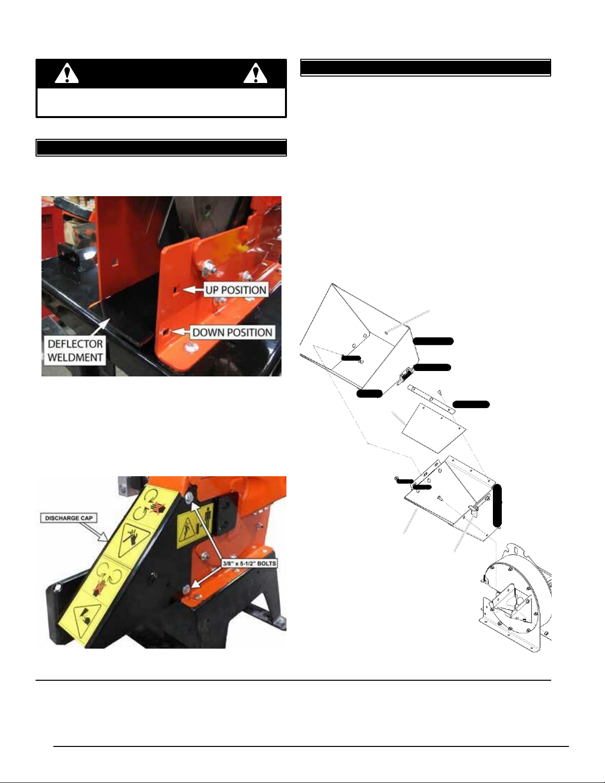
1. Move the chipper deflector weldment located inside
the chipper housing to the down position (Figure 2.1).
2
.
2
CHUTE
ASSEMB
LY
1. Attach the chipper chute to the chipper using four (4)
3/8 x 1" carriage bolts, 3/8" washers and 3/8" nuts.
Use two bolts on each side. Install with nuts on the
outside.
2. Attach the chute extension to the chipper chute using
three (3) 3/8 x 1" carriage bolts, 3/8" washers and 3/8"
nuts. Install with nuts on the outside.
3. Use the lanyard to attach the chute extension to the
middle hole on the chipper chute.
4. Attach chute flap and flap strip to the chipper chute
as shown below with the three (3) 5/16 x 1" carriage
bolts, 5/16" washers, and 5/16" nylock nuts.
5. Latch the chute extension to the lock plate on the
chipper chute.
LANYARD ATTACHES HERE
CHUTE EXTENSION
LATCH
FIGURE 2.1, CHIPPER DEFLECTOR WELDMENT
2. Slide the discharge cap onto the chipper housing
(Figure 2.2).
3. Insert two (2) 3/8" x 5-1/2" bolts into the bolt holes on
the chipper housing and tighten using 3/8" washers
and 3/8" nylock nuts.
CHUTE FLAP
FLAP STRIP
CHIPPER CHUTE
LOCK PLATE
FIGURE 2.2, DISCHARGE CAP
FIGURE 2.3, CHIPPER CHUTE EXTENSION

2
Section
ASSEMBLY
4
4.5 INCH HYDRAULIC CHIPPER
3
Section
FEATURES & CONTROLS
Understanding how your machine works will help you achieve the best results when using your machine. The following
descriptions define the features and controls of your machine.
CHIPPER CHUTE
Feed branches no larger than 4.5 inches in diameter into the chipper chute.
CHIPPER DEFLECTOR
Chipped material exits out the chipper deflector and onto the ground.An optional chipper discharge tube is also available
(PN 74634-00).
CHUTE EXTENSION
An additional safety feature to keep the operator from touching or being pulled into the chipper blades. The extension
should be unlatched and rotated open on its hinge when transporting the chipper.
FEMALE COUPLER/MALE COUPLER
Connect the couplers to the
appropriate connectors on the utility
loader. Note that there is a zip tie
around the pressure hose.
UTILITY LOADER MOUNT
Use this mount to secure and
transport the chipper with a utility
loader.
CHUTE EXTENSION
FEMALE
COUPLER
(PRESSURE)
MALE
COUPLER
CHIPPER
CHUTE
CHIPPER
DEFLECTOR
UTILITY

4.5 INCH HYDRAULIC CHIPPER
1
4
LOADER
MOUNT
4
Section
OPERATION
6
4.5 INCH HYDRAULIC CHIPPER
As with any other piece of outdoor equipment, getting the
feel for how your machine operates and getting to know
the best techniques for particular jobs are important to
overall good performance.
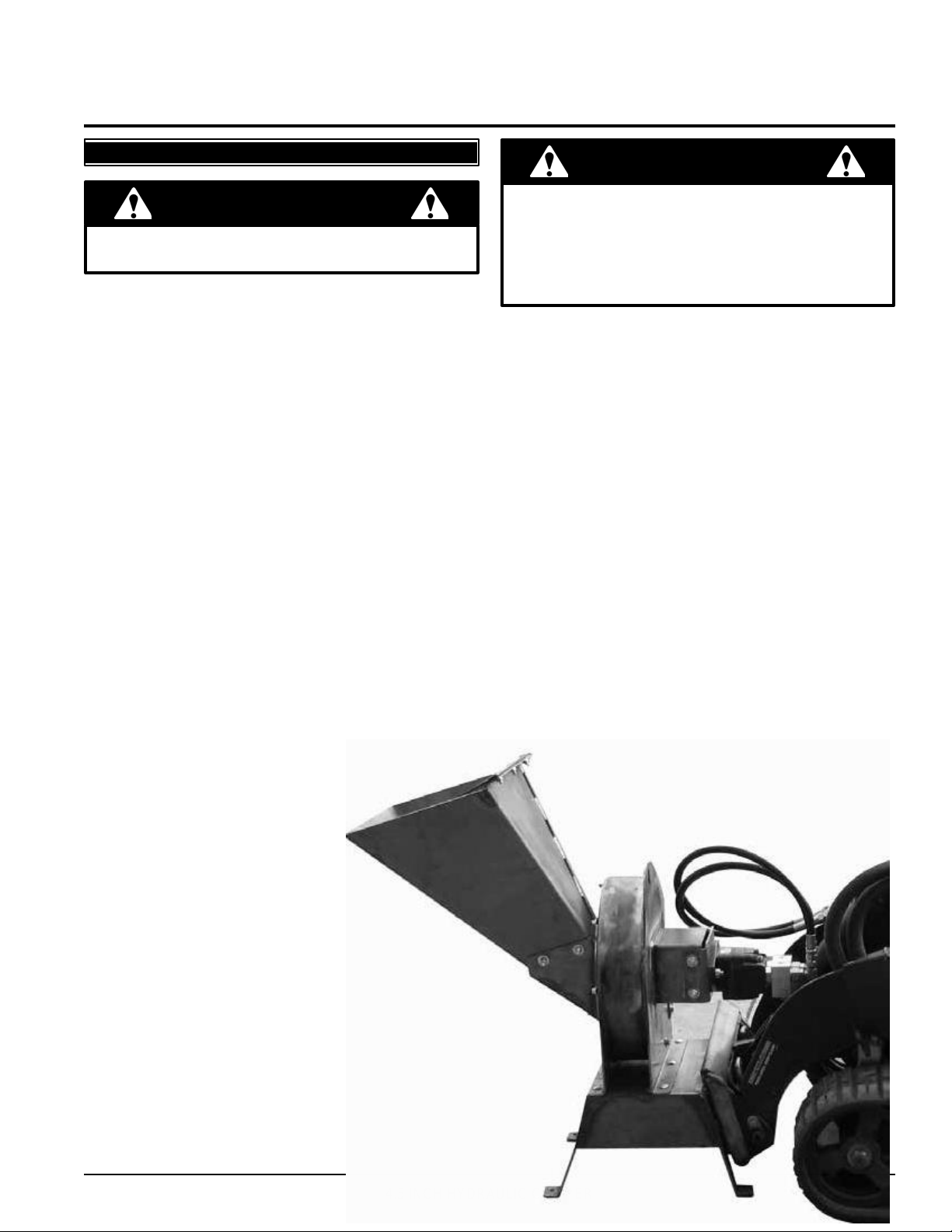
CHIPPING OPERATION
The chipping operation takes place on the front of the
machine, where hardened steel chipper blades are
mounted on a rotating rotor assembly. Material fed into
the chipper chute is sliced into small chips and propelled
out through the chipper deflector.
WARNING
Move machine to a clear, level area outdoors before
starting. Do not operate in the vicinity of bystanders.
Make sure cutting chamber is empty before starting.
WARNING
Before operating your machine, be sure you read and
understand all
safety, controls and operating
instructions
in this owner's manual and on your machine. Failure to
follow these instructions can result in serious injury or
property damage.
4.2 MOUNTING THE CHIPPER TO A
UTILITY LOADER
Consult the owner's manual for your utility loader
before mounting the chipper!
1. Position the chipper on a level surface.
2. Ensure that the mount plates are free of dirt or debris.
3. Start the engine on the utility loader.
4. Direct the loader mount plate into the upper lip of the
chipper receiver plate.
5. Raise the loader arms while tilting back the mount
plate.
6. Stop the engine.
7. Engage loader pins to ensure the chipper is securely
mounted.
IMPORT
ANT
If the pins do not rotate to the engaged position, the
mount plate is not fully aligned with the holes in the
chipper receiver plate. Check the chipper plate and
clean it if necessary.
W
ARNING
If your loader creates back pressure greater than 250
psi, a case drain will have to be added to prevent
damage to the seal on the chipper rotor motor. Contact
your dealer for more information.
4.1 RECOMMENDED HYDRAULIC FLOW
RATES
Minimum flow rate
10 gal/min
Maximum flow rate
14 gal/min
Standard hydraulic pressure
3000 psi
W
ARNING
Exceeding the recommended flow rates can cause
severe damage and void the chipper warranty!
4.3 REMOVING THE CHIPPER FROM A
UTILITY LOADER
1. Lower the chipper to the shipping pallet or base of
similar size. (30" x 50")
2. Stop the engine.
3. Disengage the pins.
4. Relieve pressure on the hydraulic couplers (see your
owner's manual).
5. Rotate the ball sleeve so the grooves are aligned with
the pins in the female coupler.
6. Retract the sleeve on the female coupler until the
couplers disconnect.
7. Repeat for the male hose.
8. Attach the chipper to the pallet using the four holes
located in the skids of the chipper base.
9. Start the engine, tilt the mount plate forward, and back
the loader away from the chipper.
4.5 INCH HYDRAULIC CHIPPER
1
6
WARNING
4
.
4
CONNECTING
COUPLERS
WARNING
OPERATION
Handle pressurized hydraulic fluid carefully. Escaping
pressurized hydraulic fluid may penetrate your skin
Hydraulic lines may be under pressure due to testing
done at the factory.
Consult the owner's manual for your utility loader
before mounting the chipper!
The chipper is equipped to attach to flush face couplers.
The chipper is shipped with -10 size hydraulic couplers
fitted on the hoses. If your utility loader is fitted with
anything other than -10 sized flush face couplers on the
main lines, you must replace the couplers supplied with
the chipper.
Atie wrap is used to indicatethe pressure line. Be sure
to connect the hydraulic hoses to the proper ports.
TO CONNECT:
1. Stop the engine on the utility loader.
2. Remove dirt and debris from the surface of the
couplers.
3. Visually check the couplers for damage; replace if
damage is found.
4. Relieve the hydraulic pressure in the utility loader (see
your owner's manual).
5. Push the chipper male coupler into the loader female
coupler. Full connection is made when the ball release
sleeve slides forward on the
female coupler
.
6. Turn the sleeve so that it is
rotated away from the locking
pin to prevent accidental
disconnection.
7. Push the chipper female
coupler into the loader male
coupler.
TO DISCONNECT:
1. Lower the chipper to the
ground.
2. Stop the engine.
3. Relieve pressure on the
hydraulic couplers (see your
owner's manual).
4. Rotate the ball sleeve so the
grooves are aligned with the
pins in the female coupler.
5. Retract the sleeve on the
female coupler until the
couplers disconnect.
6. Repeat for the male hose.

4
Section
OPERATION
6
4.5 INCH HYDRAULIC CHIPPER
causing serious injury. This fluid may also be hot
enough to burn. Serious infection or reactions can
develop if immediate proper medical treatment is not
administered.
4.5 STARTING THE CHIPPER
Running the utility loader chipper is a one- or two-person
operation. If the loader requires an operator in the
driveseat, two people are needed. The chipper engages
with the hydraulics of the utility loader.
1. Set parking brake.
2. Engage the hydraulics of the utility loader to supply
power to the unit. The chipper will start to spin.
3. Bring the unit up to speed.
4. The chipper is ready to chip.
4
.
6
STOPPING
THE
CHIPPER
Slow down the engine of the utility loader to idle and after
several seconds disengage the utility loader hydraulics.

4.5 INCH HYDRAULIC CHIPPER
1
8
OPERATION
4
.
7
OPERA
TING
THE
CHIPPER
CAUTION
●Obtain and wear safety glasses at all times when
operating the machine.
● Do not wear loose fitting clothing.
●The operator should always wear heavy boots,
gloves, pants and a long-sleeved shirt.
●Use common sense and practice safety to protect
yourself from branches, sharp objects, and other
harmful objects.
W
ARNING
●Never lean over the chipper chute to push objects
into the cutting device. Use a push stick or brush
paddle.
●Never use shovels or forks to feed brush. They can
cause extensive damage if they contact the blades.
In addition, metal pieces can be ejected from the
chipper chute and cause serious injury or death.
● Never feed brush into the chute with your feet.
●Never use hands or feet to clear materials that
build up in the chute.
W
ARNING
Read and follow all safety instructions in this manual.
Failure to operate the machine in accordance with
the safety instructions MAY RESULT IN PERSONAL
INJURY!
The machine chips a variety of materials into a more
readily decomposed or handled condition. The following
guidelines will help you get started.
1. Run unit at full operating speed before starting to
chip material.
2. Limbs fed in to the chipper chute must be 4.5
inches (11.4 cm) in diameter or less. Trim side
branches that cannot be bent enough to feed into the
chipper chute. Hold small diameter branches together
in a bundle and feed in simultaneously.
3. Exclude pieces of metal, rocks, bottles, cans, and
other foreign objects when feeding material into the
machine.
4. Feed brush from the side of the chipper chute,
rather than from the front. Step aside to avoid being
hit by the brush moving into the chipper.
5. Place limb, butt end first, into the chipper chute
until it contacts the chipper blades. The actual feed
rate of the limb into the chipper will depend on the type
of material fed and sharpness of the cutting blades.
6. If the engine slows to where it may stall, stop
feeding material and allow the engine to recover.
Feed material more evenly.
7. If the chipper jams, remove the branch and rotate it
before reinserting it into the chute. Alternately insert
and retract the limb or insert continuously at a rate that
will not kill the engine.
8. Alternate greener material with dry material to
lubricate the chipping blades for longer life and better
performance. Chipping dead, dry material will create
heat and dull the chipping blades quickly.
9. Sharpen the chipping blades periodically. Check
the sharpness of the blades every 5-15 hours. Refer to
the Service and Maintenance section for sharpening
instructions.
10. Do not drive the utility loader while chipping.
W
ARNING
To prevent personal injury or property damage: shut
off engine and make sure that all moving parts have
come to a complete stop before, servicing, adjusting or
repairing. Disconnect the battery and remove ignition
key where applicable.
8
4.5 INCH HYDRAULIC CHIPPER
5
Section SERVICE & MAINTENANCE
5
.
1
MAINTENANCE
SCHEDULE
The items listed in this service and maintenance schedule
are to be checked, and if necessary, corrective action
taken. This schedule is designed for units operating under
normal conditions. If the unit is operating in adverse or
severe conditions, it may be necessary for the items to be
checked and serviced more frequently.
SEE ENGINE OWNER'S MANUAL FOR FURTHER
ENGINE MAINTENANCE AND TROUBLESHOOTING
INFORMATION.
WARNING
To prevent personal injury or property damage: shut
off engine and make sure that all moving parts have
come to a complete stop before, servicing, adjusting or
repairing. Disconnect the battery and remove ignition
key where applicable.
SERVICE AND MAINTENANCE SCHEDULE
FREQUENCY
COMPONENT
MAINTENANCE REQUIRED
BEFORE
EACH USE
EVERY 8
HOURS
EVERY 50
HOURS
All internal and external
nuts and bolts
Check tightness
●
Chipper anvil
Check clearance and re-torque to
75 ft-lbs. (1)
●
Chipper blades
Check sharpness and re-torque to
120 ft-lbs. (1)
●
Entire machine
Clean
●
Grease zerks
Lube
●
(1) Perform more frequently when chipping dry or dirty wood.
As the limited warranty states, failure by the owner to perform normal maintenance will void the machine's
warranty. The aggressive, high-speed nature of chipping requires the owner to perform the above listed
normal maintenance. Special consideration to maintain and re-torque the chipper anvil, chipper blades, and
all internal and external nuts and bolts is the sole responsibility of the owner. Failure by the owner to do so
shall be cause for denial of warranty.
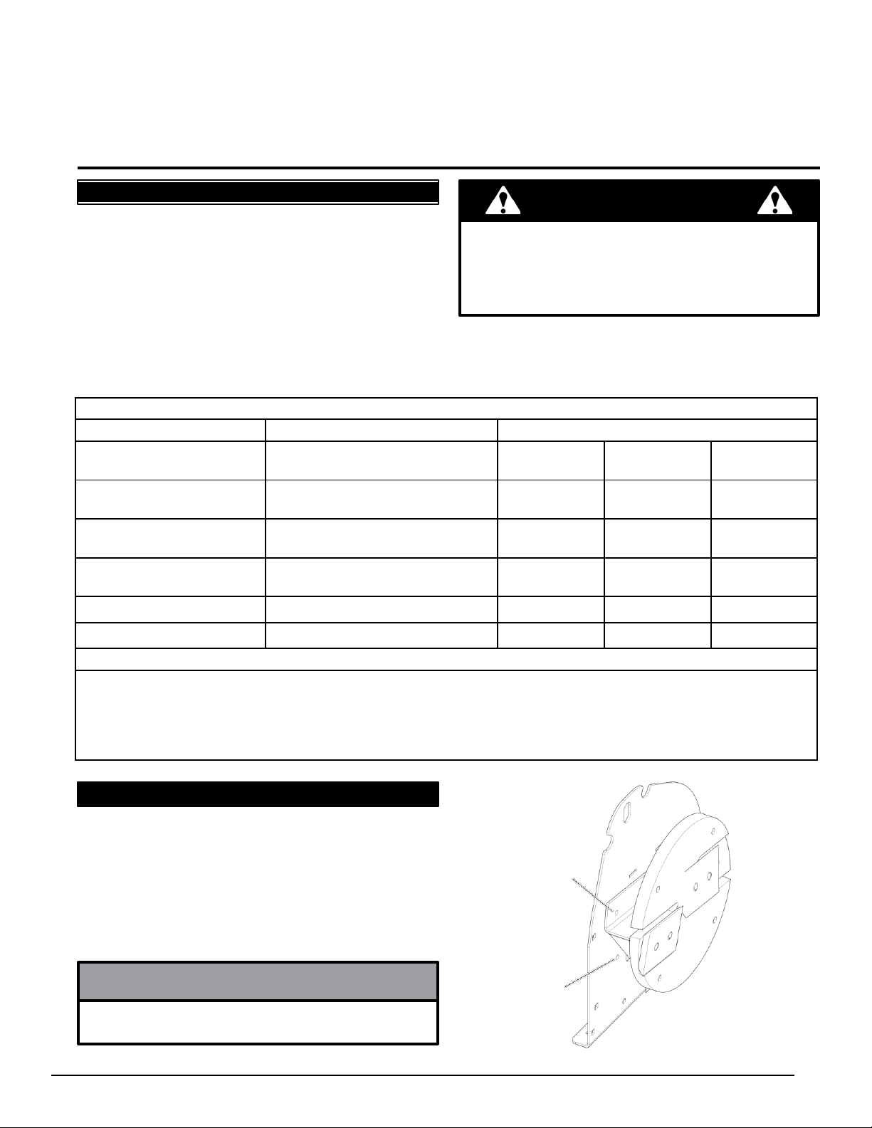
5.2 INSTALLING THE ROTOR LOCK
When working on the rotor assembly, use the lock
mechanism at all times (Figure 5.1). Follow the steps
below to install the rotor lock:
1. Rotate the rotor until the hole on the paddle is aligned
with the hole on the chipper housing (Figure 5.1).
2. Install a punch or screwdriver into the holes.
MATCHING HOLE
ON ROTOR PADDLE
CHIPPER
ROTOR
NOTE
One of the 3/8 x 5-1/2" bolts from the chipper deflector
can also be used to lock the rotor.
ROTOR
LOCK HOLE
FIGURE 5.1, ROTOR LOCK

4.5 INCH HYDRAULIC CHIPPER
20
W
ARNING
BEFORE INSPECTING OR SERVICING ANY PART OF THIS MACHINE, SHUT OFF POWER SOURCE
,
AND MAKE SURE ALL MOVING PARTS HAVE COME TO A COMPLETE
STOP.
5.3 CHIPPER BLADE MAINTENANCE 5.4 REMOVING THE BLADES
The chipper blades will eventually become dull, making
chipping difficult and adding extra strain on the machine.
CHECK THE SHARPNESS OF THE BLADES EVERY
5-15 HOURS OF OPERATION AND SHARPEN AS
NEEDED.
Your blades need to be sharpened if:
●Machine vibrates severely when material is fed into
the chipper.
● Small diameter branches do not self-feed.
●Chips discharge unevenly or have stringy tails,
especially when chipping green branches.
Before you sharpen the chipping blades, check for
permanent damage. Replace the blade if:
●There are cracks, broken corners or nicks greater
than 1/8" (see below).
1. Remove the chipper deflector from the chipper
housing.
2. Rotate the rotor until a blade is accessible and install
the rotor lock (Section 5.2).
3. Remove the two hex bolts holding the blade to the
rotor.
4. To access the remaining blade, remove the punch or
screwdriver, reposition the rotor, and return the punch
or screwdriver to the rotor lock hole.
5. Repeat step 2 for the remaining blade.
6. Inspect blades to see if cracks or nicks are visible (see
Section 5.3).
5
.
5
SHARPENING
THE
BLADES
The blades can be ground on a bench grinder or by a
professional.
1. Never sharpen or grind the mounting surfaces of
the blades. This will cause the edge to roll and the
blade will be damaged, resulting in poor chipping
Broken
corner
Crack greater
than 1/8" Nick greater
than 1/8" performance.
2. Regrind the angled edge of the chipping blades to 45
degrees (see below). Make sure some type of fixture
is used to correctly hold the blade at the proper angle.
3. Be careful when grinding so that the blade does
not become overheated and change color. This will
remove the heat-treated properties.
●The base of the cutting edge is worn or has been
re-sharpened so that it no longer extends past the
chipping slot (see below).
4. Use short grinding times and cool with water or some
type of liquid coolant.
5. Remove an equal amount off each blade to maintain
rotor balance.
6. Small imperfections such as nicks and burrs on
Chipper
rotor
New
blade
Chipper
rotor
Chipping slot
Blade is too
short, must
be replaced
Chipping slot
the flat side of the blade will not affect the chipping
performance of the machine.
7. For blades that have been repeatedly sharpened,
ensure that the sharpened surface extends past the
chipping slot opening. If it does not extend past the
opening, the blades should be replaced.
Sharpened
Surface
Mounting Surface
(DO NOT GRIND)
Sharpened
Surface
W
ARNING
The chipping blades are sharp!! Use care when working
on the machine to avoid injury.
45˚
.50"
Mounting Surface
(DO NOT GRIND)
This manual suits for next models
2
Table of contents
Other Spartan Equipment Chipper manuals


