INSTALLATION INSTRUCTIONS
SP-8012
½ HP Sump Pump
92-SP-8012-01
TOOLS & SUPPLIES NEEDED
IMPORTANT
RISK OF ELECTRIC SHOCK The pump is supplied with a grounding conductor and
grounding-type attachment plug. To reduce the risk of electric shock, install only on a circuit
protected by ground-fault circuit-interrupter. Always disconnect the pump from the power
source before handling or making adjustments. Always wear rubber boots when servicing in
wet areas. Make sure the pump power source is a separately fused, grounded 3-wire type
receptacle of 15-amp capacity. DO NOT REMOVE GROUND PRONG OR PLUG. DO NOT
USE AN EXTENSION CORD. Check to make sure installation is in accordance with the
National Electric Code and all applicable local codes. Installation and servicing are to be
conducted by qualified personnel.
• DO NOT pump flammable liquids.
• DO NOT use around explosive materials.
• DO NOT handle unit with wet hands or while standing in water.
• DO NOT lift the pump by the power cord.
• DO NOT handle or carry the pump by the power cord. Use the handle, or rope.
• DO NOT connect to any voltage other than that listed on the nameplate.
• DO NOT use in water over 104˚F (40˚C).
• DO NOT modify the pump in any way.
• DO NOT expose pump or discharge to freezing temperatures.
• DO NOT use this product to pump salt water or brine. Use with salt water or brine will void
the warranty. Pump water only.
The sump pit must be a minimum of 12” diameter x 10” depth for Vertical switch models usage.
• Do keep the pump inlet screen clear.
The pump MUST be placed on a solid foundation, such as a brick, stone, or other flat
heavy surface. Do not place the pump directly on the ground in sandy or rocky surfaces.
Earth, sand, or gravel that enters the pump would damage the impeller of the sump and
cause flooding. Sand or mud-choked pumps can be back-flushed clean.
• Extended usage of the pump in a partially submerged or non-submerged situation may
cause the pump to overheat due to lack of heat dissipation from the water. If this occurs, the
pump will shut itself off until the motor cools to its normal temperature. Repeated overheating
may cause damage to the pump.
WARNING
Adjustable
Wrench
Flat Tip
Screwdriver
Dedicated
120V, 60 Hz
15A GFCI
SHOCK HAZARD:
Turn OFF electrical power at Fuse Box or
Circuit Breaker before performing any work!
SAFETY TIPS:
Be sure to read and understand all instructions
before beginning installation.
Inspect all connections after installation.
Be sure to wear proper eye protection.
800-537-2107 www.speakman.com
NEED HELP?
For additional assistance or service please contact:
1
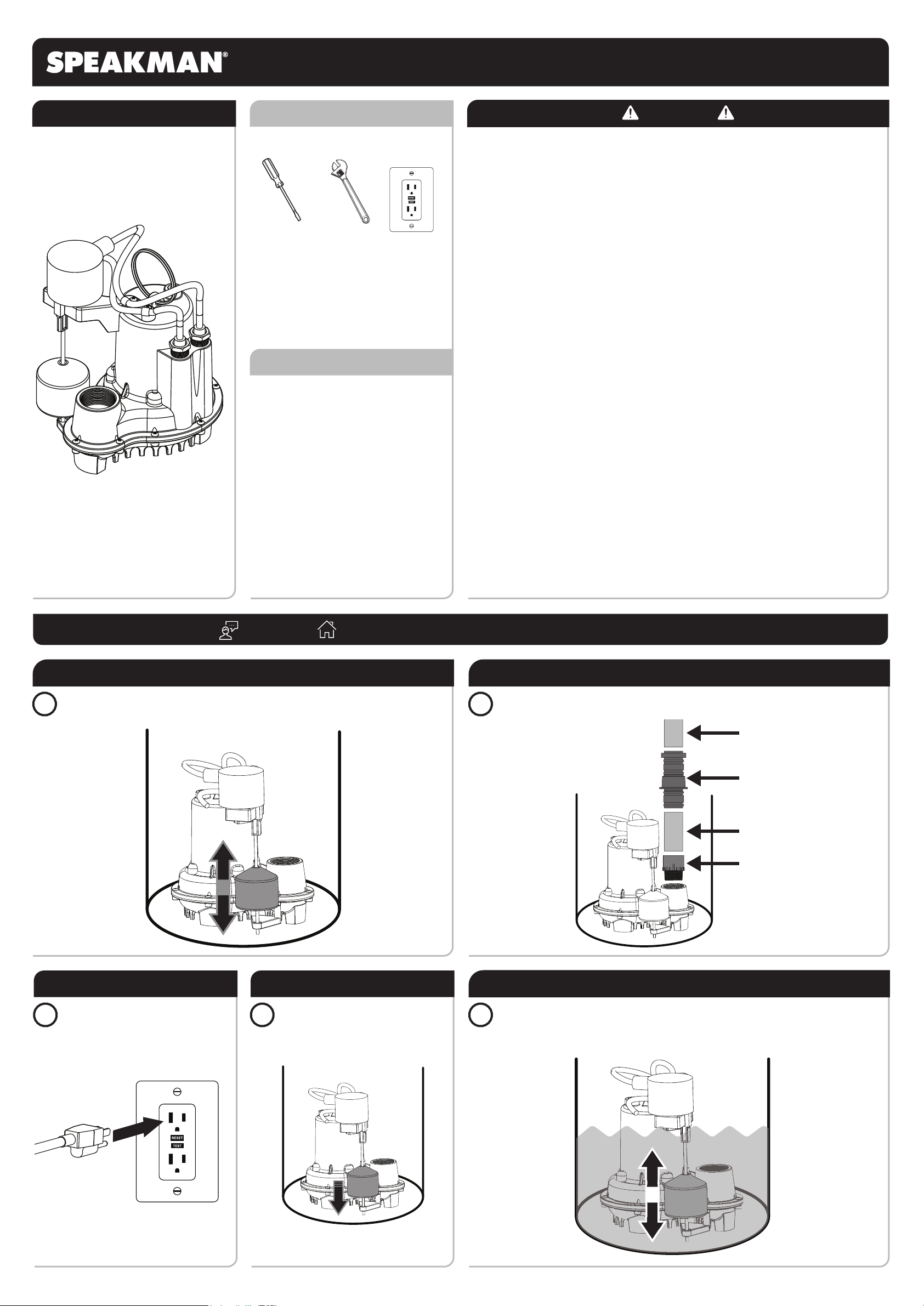
POSITION PUMP
Position your Pump in the sump and be sure that the Float Switch moves freely without touching
the wall of the sump or other obstructions. Be sure the incoming water does not interfere with
Float Switch. Ensure the Pump is sitting on a hard surface.
2
INSTALL DISCHARGE LINE
Install a 1-1/2” Male Pipe Adapter, 1-1/2” Discharge Pipe, and Check Valve in accordance to
code.
1-1/2” Male Pipe Adapter
1-1/2” Discharge Pipe
Check Valve
To Discharge Location
3
PLUG IN
Plug Power Cord into a properly
grounded GFCI outlet. A dedicated AC
circuit of 120v 15A is required.
Verify that the Power Cord routing does not
interfere with the Float Switch.
4
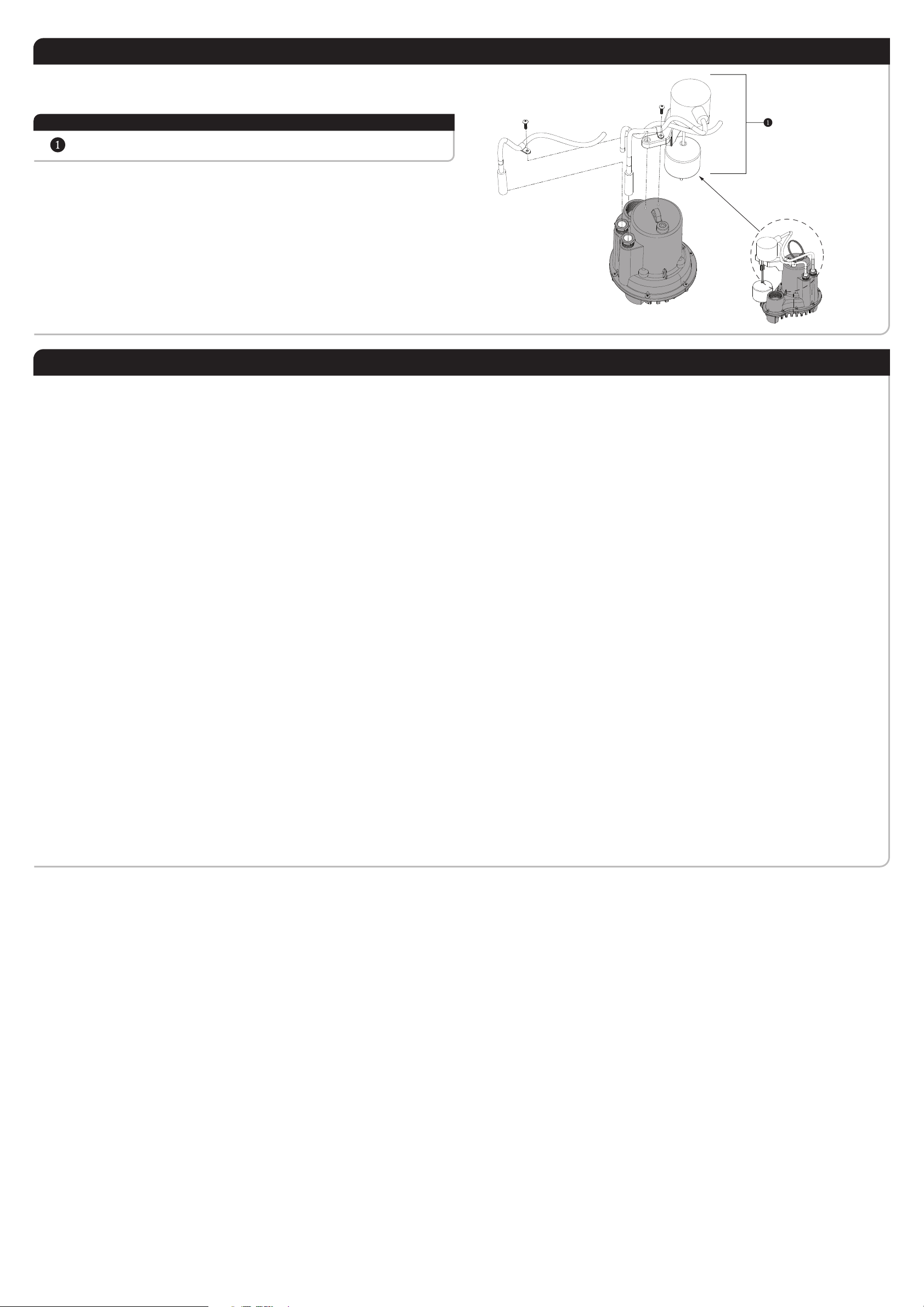
VERIFY FLOAT SWITCH POSITION
With the Pump plugged in and the sump
dry, the Pump should not activate. If
needed, adjust Float Level by
repositioning the rubber bushing on the
bottom of the Float Rod.
Verify that the Power Cord routing does not
interfere with the Float Switch.
5
TEST FOR PROPER OPERATION
Once installation is complete, check the functionality by filling the sump with water using a bucket
or hose. The unit should activate, pump the water from the sump, and turn off once the water
level reaches the set point of the float. If needed, adjust Float Level by repositioning the rubber
bushing on the bottom of the Float Rod.