Special Optics 56B-30-1X-4X User manual
1
Motorized Zoom Beam Expander (56B-30-1X-4X)
Users’ Manual
Special Optics’ Motorized Zoom Beam Expanders are designed to receive a collimated laser
beam and to increase the beam diameter while maintaining a collimated output beam.
Model 56B-30-1X-4X-λis a beam expander that offers 13 different expansion ratios: 1.00X,
1.25X, 1.50X, …4.00X. The user specifies a wavelength when ordering the beam expander. This
assures that the antireflection coatings on the lenses will be optimized for the user’s primary
wavelength. Model 56B-30-1X-4X is designed to operate at 13 standard wavelengths: 256 nm,
355 nm, 458 nm, 488 nm, 514.5 nm, 532 nm, 632.8 nm, 780 nm, 800 nm, 1064 nm, and 1550 nm.
Custom versions for other wavelengths are available. Since the fused-silica optics are identical for
all wavelengths, only the wavelength settings in software need to be changed. Special Optics has
developed a Dynamic Link Library (dll) to operate our Motorized Zoom Beam Expander. This dll
can be called from any program, but we provide an executable file (exe), which operates in a Win-
dows environment, to drive the dll.
1. Optical Layout
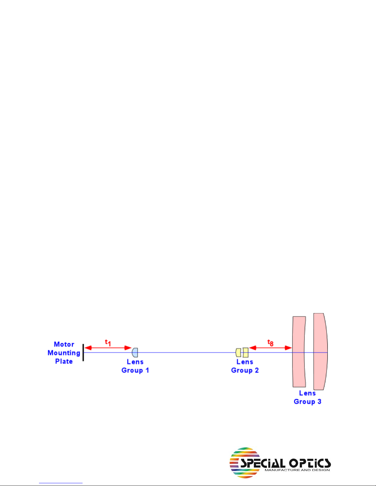
The Motorized Zoom Beam Expander comprises three lens groups, two of which move during
operation. Figure 1 shows the three lens groups and indicates that Lens Group 1 and Lens Group 2
move when the expansion ratio is changed. There are two motors in the system. Motor 1 moves
Lens Group 1, thereby controlling the air space (t1) between Lens Group 1 and the Motor Mount-
ing Plate. Motor 2 moves Lens Group 2 and controls the air space (t8) between Lens Group 2 and
Lens Group 3, which is fixed. The unit is supplied with a text files that contain nominal values of
t1and t8for eleven wavelengths and thirteen expansion ratios. These values were established at
Special Optics using a shear-plate interferometer to optimize collimation settings at all of the
expansion ratios for several wavelengths. Values for these two air spaces will vary from labora-
tory to laboratory since they are a function of the collimation properties of the testing beam. Users
should verify that the settings are optimized for their particular set of beam parameters.
Figure 1. Optical components in zoom beam expander.

2
2. Files
The system is supplied with an installation disk for a Windows operating system. The user should
double click on the setup icon to start the installation. This will install all necessary files in their
proper locations on the user’s computer. Included in this installation is National Instrument’s
Runtime Engine 8.0, which is required to operate the dll file since it includes calls to functions in
National Instruments’ LabVIEW 8.0 software. The default location for the all of the files is
C:\Program Files\Special Optics BE.
Key files that are installed include:
• Beam Expander Controller.exe - This is the executable that will operate the software for the
Zoom Beam Expander.
• BE_Controller - This is a dll (digital link library) that can be called by any programming
language.
• Config.ini - Startup file containing key parameters (see below)
• t1 and t8_λ- txt files containing air spaces for 13 expansion ratios at 11 wavelengths (λ)
• Factory Def Files - Folder containing a copy of txt files (to allow restoration if needed). The
eleven txt files containing the motor positions are stored in the default
directory. If the files become damaged, original values can be restored
by copying the original files from the 'Factory Def Files' folder into the
default directory. Do not change the default files.
• BE_Controller Configuration Settings - parameter definitions needed if programming in
C++ or another language.
Config.ini
This file identifies:
1. COM port (default = 1) over which the RS-232 communications occur. This can be
changed to another appropriate port on the user’s system.
2. M1 Offset and M2 Offset are offset values for the two motors. These are set during
calibration at Special Optics and should not be changed by the user.
3. Default wavelength. When the system is started, it will automatically display the
default wavelength on the front panel. You can change the wavelength actively on the
front panel, or you can change the default wavelength in the Config.ini file:
0 = 256 nm 1 = 355 nm 2 = 458 nm
3 = 488 nm 4 = 514 nm 5 = 532 nm
6 = 633 nm 7 = 780 nm 8 = 800 nm
9 = 1064 nm 10 = 1550 nm

3
4. Tweak step. During adjustment of the calibration, the user activates the Tweak func-
tion. Motor steps are 0.2, 0.4, or 1.0 times the tweak step in millimeters. The default
value is 0.2 mm. It is unlikely that the user will need to change this, but the option is
available.
5. File path. The default location for the files called by the program is
C:\Program Files\Special Optics BE. If you move the files to another location, this
path will need to be changed.
3. Operation
The software for the Motorized Zoom Beam Expander was written in LabVIEW 8.0 by National
Instruments. All of the key commands are complied in a dll file. We have written an executable
LabVIEW file that calls the dll to operate the system. It is not necessary to have LabVIEW
installed on your computer to operate the system. However, the installer does load National
Instruments’ Runtime Engine 8.0 on your system in order to permit calls to LabVIEW functions
from the dll.
The executable file was written in LabVIEW to provide a user-friendly graphical user interface
(GUI) to operate the zoom lens. Figure 2 shows the GUI in its start-up condition. The WAIT but-
ton is dark since the unit’s two motors begin a homing procedure on start-up. The top two lights
on the control box will remain red until the homing procedure is completed. The top light remains
red until Motor 1 has homed; the middle light remains red until Motor 2 homes. If the lower light
becomes red and one or both of the Drive Faults on the GUI become red, home the system
again using the RE-HOME button on the GUI. In Figure 2, this is the WAIT button. WAIT will
change to RE-HOME after the homing sequence has ended.
Wavelength
The Motorized Zoom Beam Expander is designed to operate over a wavelength range from 256
nm to 1550 nm. Antireflection coatings on the lenses must be changed for the different wave-
lengths, but the five internal lenses are identical for all versions of the system. We have pre-pro-
grammed the system for eleven common wavelengths (256, 355, 458, 488, 514, 532, 633, 780,
800, 1064, and 1550 nm). The pull-down menu on the GUI allows the user to select any of these
eleven wavelengths.
Expansion Ratio
The Motorized Zoom Beam Expander starts up with both motors in their home positions. Click on
the slide labelled Expansion Ratio to move the system into a collimation condition with an expan-
sion ratio given by the slide position and the readout at the bottom of the slide. This version of the
Motorized Zoom Beam Expander is set for thirteen expansion ratios (1.00X, 1.25X, 1.50X, …
4.00X). Each time the user moves the slide or clicks on it, the software determines the calibrated
positions for Motor 1 and Motor 2 and moves both lens carriages to the proper locations. The pre-
set motor positions for each wavelength and expansion ratio are stored in txt files (e. g.,
't1 and t8_633.txt' lists 13 expansion ratios and air spaces at 633 nm). The air spaces in the txt
files are converted to motor positions by the dll.

4
Tweak
Because beam divergences of input test beams vary, it is possible that the factory settings of lens
positions may not be perfect for the user’s system. We have provided a Tweak control to make
adjustments to the lens positions. There are three speeds (slow, med, and max) in both the positive
and negative directions. Moving the slide to one of these positions will cause both of the lens
groups to shift slightly from their original positions. The lens carriages will make a series of
movements until the user moves the slide back to the zero position. The software automatically
updates the appropriate txt file so that the stored lens positions will be the values determined by
the Tweak operation. For the entire file to be adjusted, the user must tweak the positions for all 13
expansion ratios (1.00X, 1.25X, 1.50X, … 4.00X). When you restart the system, the Motorized
Zoom Beam Expander will move to the values determined by the user during calibration (tweak-
ing) the last time the system was operated. Only the txt file for the selected wavelength will be
updated. All other txt files will retain their factory values.
Figure 2. GUI for Special Optics’ Motorized Zoom Beam Expander (56C-30-1X-4X-λ).
Table of contents
Other Special Optics Extender manuals


