SPEED LEADER LVP6000 User manual

User Manual
LVP6000
Video Processor
Seamless Switcher
SHENZHEN SPEEDLEADER TECHNOLOGY

Page 1 of 53
S
HENZHEN
S
PEEDLEADER TE
C
HN
O
L
O
G
Y
CO
.
,
LTD. LED Vi
deo
Pr
ocesso
r
Table of contents
Overview ................................................................................................5
About LVP6000 ............................................................................................5
Features .........................................................................................................5
Installation .............................................................................................7
Install LVP6000 ............................................................................................7
Rear panel......................................................................................................8
Definitions ............................................................................................10
Operation .............................................................................................10
Mode descriptions of LVP6000...................................................................10
Introduction to front panel and keys............................................................11
Menu system overview................................................................................16
Default menu introductions .........................................................................17
Main menu introductions.............................................................................19
Image quality menu .....................................................................................20
Crop menu ...................................................................................................21
Output menu ................................................................................................22
Switcher mode.............................................................................................22
Splicing mode..............................................................................................23
Resoluting mode..........................................................................................23
Splice menu .................................................................................................26
Effect menu .................................................................................................28
Function menu.............................................................................................30
Advanced menu...........................................................................................32
System menu .............................................................................................32
Shortcut menu..............................................................................................33

Page 2 of 53
S
HENZHEN
S
PEEDLEADER TE
C
HN
O
L
O
G
Y
CO
.
,
LTD. LED Vi
deo
Pr
ocesso
r
Splice operation ...................................................................................37
Setting and application of single-machine splice..............................37
Setting and application of multi-machine splice..........................................39
Specifications ...........................................................................................46
Troubleshooting ......................................................................................52
Page 3 of 53
S
HENZHEN
S
PEEDLEADER TE
C
HN
O
L
O
G
Y
CO
.
,
LTD. LED Vi
deo
Pr
ocesso
r
About the Manual
Without the written permission of the company, it is forbidden for any company or
individual to imitate, copy, or transcribe part or all of the contents of the manual. It is not
allowed to have the commodity publicity or achieve any commercial or profit-seeking
purpose in any form (electronic form, mechanical form, photocopying form, recording
form, or other possible ways).
Please carefully read this manual before using this equipment. All the product
specifications and information mentioned in the manual are only for reference. If there is
the content updating, the company will not make further notice. Unless there is a special
agreement, this manual is only taken as an instruction, and all statements and information
will not constitute a guarantee of any kind.
Brand Royalty
VGA and XGA are the registered trademarks of IBM Corporation.
VESA is a trademark of the Video Electronics Standards Association.
The logo of HDMI and High-Definition Multimedia Interface are the trademark of HDMI
Licensing LLC.
Safety Instructions
This equipment must be connected with ground wire.
This equipment needs a rated power voltage. Ensure that the input voltage
error should be between - 10% and +10%.
Do not connect AC power cord with another AC power cord which may lead to
excessive noise.
Please use the equipment when the surrounding temperature is from -10 ℃to

Page 4 of 53
S
HENZHEN
S
PEEDLEADER TE
C
HN
O
L
O
G
Y
CO
.
,
LTD. LED Vi
deo
Pr
ocesso
r
45 ℃, and the relative humidity is 90% or less than that.
Do not use this equipment in certain special circumstances, such as, closing to
a heat source, which may cause overheating of the equipment and damage it.
Please use it in a well-ventilated place and pay attention not to block the
equipment vents.
Do not expose this equipment in the place which has the possibility for
accidental collision or vibration, and reinforcement processing is necessary in
the vibration place.
When you use the equipment, please make sure that there are no objects, such
as water and metal objects, inside the equipment. Otherwise, it will damage the
equipment and cause a fire.
If there is any irregularity or abnormality for the equipment, please
immediately turn off the power supply, disconnect the AC power cord, and see
“Trouble Clearing”.
If this equipment is damaged, do not disassemble it. Please contact our
maintenance service department.

Page 5 of 53
S
HENZHEN
S
PEEDLEADER TE
C
HN
O
L
O
G
Y
CO
.
,
LTD. LED Vi
deo
Pr
ocesso
r
Overview
About LVP6000
LVP6000seriesconsistsofthefollowingfourmodels:
●LVP6000:9‐channelsignalinput
●LVP6000S:10‐channelsignalinput(includingSDImodule)
●LVP6000A: 9‐channelsignalinputandanaudiomodule
●LVP6000SA: 10‐channelsignalinput(includingSDImodule)andan
audiomodule
Features
LVP6000 is a video processor which supports the resolution of input signal up to
4K*2K and the output up to 4K*1K, and it provides a perfect solution to the demands of
high-quality, point-to-point applications of automobile exhibitions and high-end
conferences, etc.
LVP6000 is also a seamless switcher with rich switching effects and preview output.
The original knob switching mode and rich switching effects can meet the demands of
various advanced functions required by the high-end presentation environment.
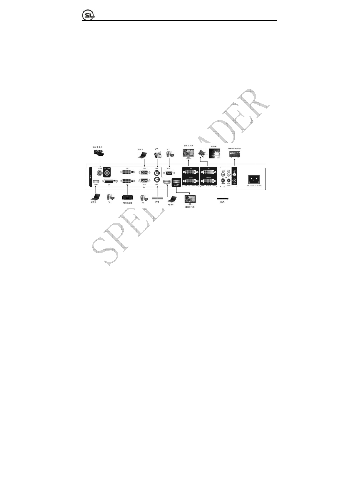
Fig. 1-1 shows a typical application of the LVP6000. It can receive a variety of
signals and various resolution (which can support SD to UHD) inputs as follows:
Page 6 of 53
S
HENZHEN
S
PEEDLEADER TE
C
HN
O
L
O
G
Y
CO
.
,
LTD. LED Vi
deo
Pr
ocesso
r
●VIDEO (NTSC, PAL, SECAM) video
●VGA (VESA standard) video
●HDMI (HDMI 1.4 / DVI 1.0) video
●DVI (VESA standard) video
●DP (DP 1.2) video
●3G-SDI video (optional)
Fig. 1-1 Typical Application of LVP6000
LVP6000 has two channels outputs for preview(A) and program(B), each output
applies DVI-I and DVI-D interface, which can realize two-channel DVI and one-channel
VGA (using DVI to VGA connector to connect the DVI-I interface) and meet more device
attachment. The user can determine seamless switching and effect switching of any
channel at random.
The user can set any two input video into preview and program output and achieve
the real seamless switching or other switching effect easily.

Page 7 of 53
S
HENZHEN
S
PEEDLEADER TE
C
HN
O
L
O
G
Y
CO
.
,
LTD. LED Vi
deo
Pr
ocesso
r
The user can define the resolution of the input video and output signal freely, meeting
various special application requirements.
LVP6000 is more humanized in design, stronger in function and easy to use. Only tapping
your fingers on the simple button panel and menu system can finish complex settings. Rich
physical interfaces are provided to meet the requirements of the common output equipment.
And the rotary knob can adjust relevant parameters of the picture quickly, which is
convenient for the users.
Installation
Install LVP6000
The user can choose whether to install LVP6000 to the rack or flight case. LVP6000
is a standard 1.5U chassis, with the size of 6.5cm (Height) x 44cm (Width) x 32CM
(Depth). While installing, please avoid scratching the case and use cushion for fixing
suspension loop.
Fig. 2-1 Installation of LVP6000
Page 8 of 53
S
HENZHEN
S
PEEDLEADER TE
C
HN
O
L
O
G
Y
CO
.
,
LTD. LED Vi
deo
Pr
ocesso
r
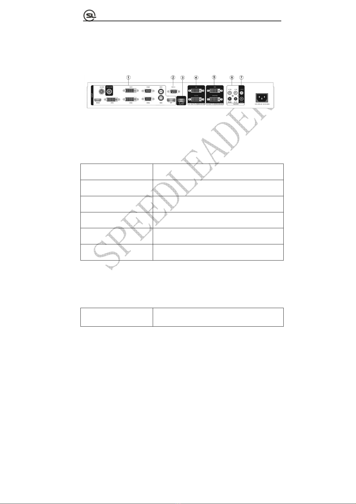
Rear panel
The rear panel is as shown in Fig. 2-2:
Fig. 2-2 Connection Terminals of LVP6000 Rear Panel
①Video input
VID1, VID2 2-channel composite video input port (BNC seat)
VGA1, VGA2 2-channel VGA input port (DB15 seat)
DVI1, DVI2, DVI3 3-channel DVI input port (DVI-I seat)
HDMI 1-channel HDMI input port (HDMI seat)
DP 1-channel DP input port (DP seat)
SDI (optional) 1-channel SDI input port (BNC seat)
②Communication interface
RS-232 RS-232 interface (DB9 seat)

Page 9 of 53
S
HENZHEN
S
PEEDLEADER TE
C
HN
O
L
O
G
Y
CO
.
,
LTD. LED Vi
deo
Pr
ocesso
r
③DP looping-out interface
DP LOOP(OUTPUT) DP looping-out port (DP seat)
④⑤Output interface
A OUTPUT(PREVIEW)
Preview output interface which is connected to a
preview display usually.
B OUTPUT(PROGRAM)
Program output interface which output to an LED
sending card or a projector usually.
Two DVI-I seats are employed, which can output DVI and VGA signals at the same time.
When VGA signals are output, a DVI-VGA adapter shall be used to connect the seats to
the DVI-I interface.
⑥Audio interface
L1 IN, R1 IN, L2 IN, R2 IN Two groups of audio input interfaces
L OUT, R OUT One group of audio output interfaces
⑦AC power interface
Page 10 of 53
S
HENZHEN
S
PEEDLEADER TE
C
HN
O
L
O
G
Y
CO
.
,
LTD. LED Vi
deo
Pr
ocesso
r
LVP6000 provides a standard IEC power, with the input power of 100 ~ 240VAC, 50Hz
or 60Hz, at the same time, the ground wire of the power supply must be grounded to avoid
equipment damage or the electric shock to human body.
Definitions
Preview signal Signal name displayed in the preview area at default menu.
Program signal Signals name displayed in the program area at default menu.
Preview picture Picture connected by the preview output (PREVIEW) in switcher mode
Program picture
Picture connected by the program output (PROGRAM) in switcher
mode
Spliced picture
Picture spliced by the A output or the B output interface in splicing
mode.
PIP picture
Picture overlaid on the program or spliced picture when PIP effect is
enabled.
Operation
Mode descriptions of LVP6000
Switcher mode: It is the seamless switcher with rich switching effects and preview and
program
Page 11 of 53
S
HENZHEN
S
PEEDLEADER TE
C
HN
O
L
O
G
Y
CO
.
,
LTD. LED Vi
deo
Pr
ocesso
r
output. The user can choose the switcher mode in "OUTPUT→Output Timing"
and connect a monitor which displaying the preview picture to A OUTPUT
(PREVIW) to and connect B OUTPUT (PREVIW) to LED screen or project
to display the program picture.
Splicing mode: This mode is used for two picture splicing. The user can choose the
splicing mode in " OUTPUT→Output Timing" and connect A OUTPUT
(PREVIW) and B OUTPUT (PREVIW) to the two LED screens respectively to
realize the picture splicing function of the two LED screens.
Introductions to Front Panel and Keys
A 240*64 LED is adopted by the LVP6000 processor to indicate the current state,
menu selection, data state and other parameters. Background lights of the keys can reflect
the current input selection and operation, etc. Hence, the user can operate the whole menu
system easily through the keys and rotary knobs as well as the state of the LCD screen and
background lights of the keys.
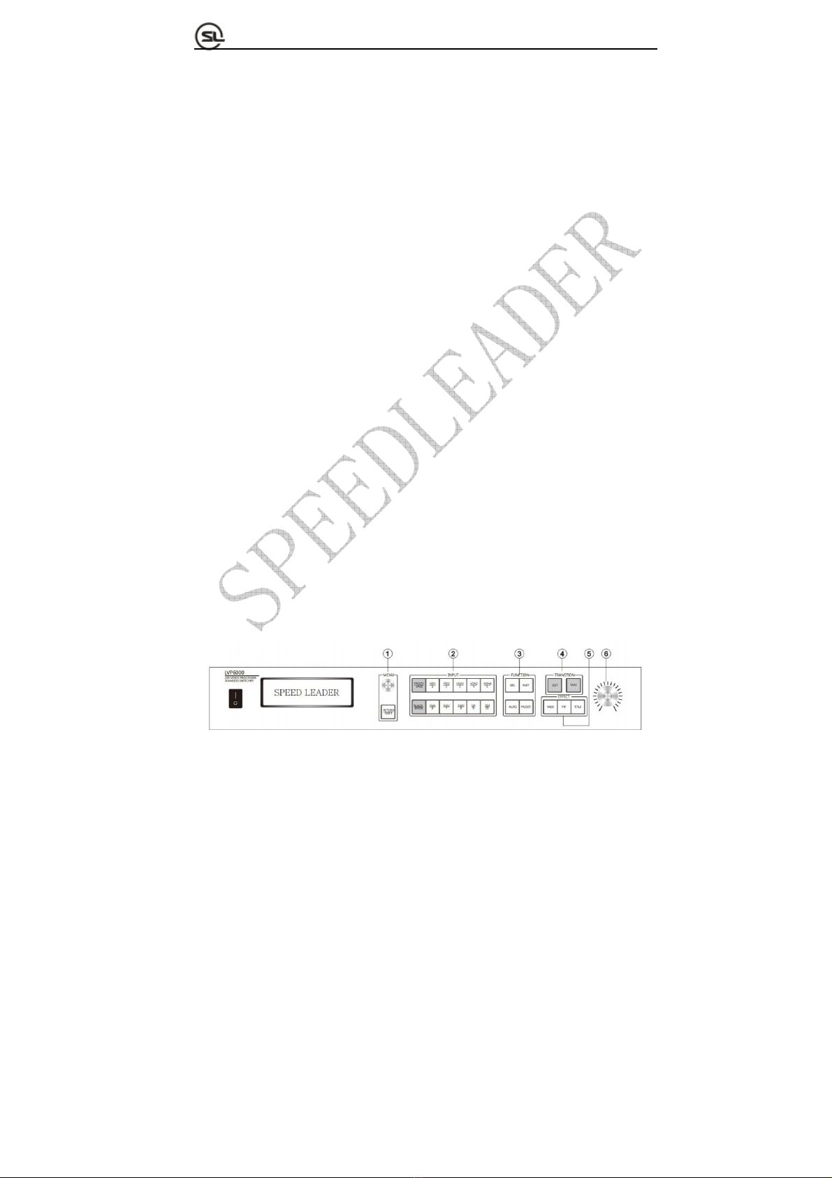
All controls and indications of the processor are focused on the front panel (Fig. 4-1).
The keys on the front panel can be divided into six areas: MENU, INPUT, FUNCTION,
TRANSITION, EFFECT and Switch Knobs.
Fig. 4-1 LVP6000 Front Panel

Page 12 of 53
S
HENZHEN
S
PEEDLEADER TE
C
HN
O
L
O
G
Y
CO
.
,
LTD. LED Vi
deo
Pr
ocesso
r
①MENU area
The area includes RETURN and MENU key, the MENU key can be rotated left and
right and be pressed down.
MENU key
1. Rotate the MENU key left and right can adjust menu options and parameters left and
right or up and down, or adjust the size and position of the output window.
2. Press MENU key can enter a specific menu or confirm the operation or realize other
functions.
3. Press MENU key at the default menu can enter the main menu interface.
RETURN/SHIFT key
1. Press the key can return to the upper menu.
2. It can be matched with the keys in INPUT area to realize program input video switching,
black screen output and screen freeze (detailed in INPUT area) as a combination key.
Note: Operation instructions for combination key formed by "SHIFT+ other keys":
Press SHIFT key continuously and simultaneously press other keys, thereby
finishing the operation of the combination key.
②INPUT area
The area includes FREEZE key, BLACK key and 10-channel input keys.
FREEZE/SAVE key

Page 13 of 53
S
HENZHEN
S
PEEDLEADER TE
C
HN
O
L
O
G
Y
CO
.
,
LTD. LED Vi
deo
Pr
ocesso
r
1. Freeze and lock the preview picture. Press\ the key can enable the freeze function,
pressing the key again or choosing the other inputs can cancel the freeze function.When
the FREEZE key is enabled, key light turns on.
2. Press SHIFT+FREEZE key can freeze the program picture
3. Storing function can be realized in PRESET state (channel key in INPUT area is on)
BLACK/ERASE key
1. Press the key can make the preview picture to the black screen. Press the BLACK key
again can cancel the black screen output.When the BLACK key is enabled, the key light is
on.
2. Press SHIFT+BLACK key makes the program picture to the black screen
3. Erase function can be realized in PRESET state.
Input channel key
1. Input channel function
PREVIEW channel switching: Press the corresponding channel key in the area (the light of
the key is on).
PROGRAM channel switching: Press RETURN/SHIFT key continuously and then press
the corresponding channel key.
2. Numeric key function
Selection for preset mode number can be realized in PRESET state (channel key in INPUT
area is normally on). For more descriptions, refer to " Menu system→PRESET shortcut
menu".
Page 14 of 53
S
HENZHEN
S
PEEDLEADER TE
C
HN
O
L
O
G
Y
CO
.
,
LTD. LED Vi
deo
Pr
ocesso
r
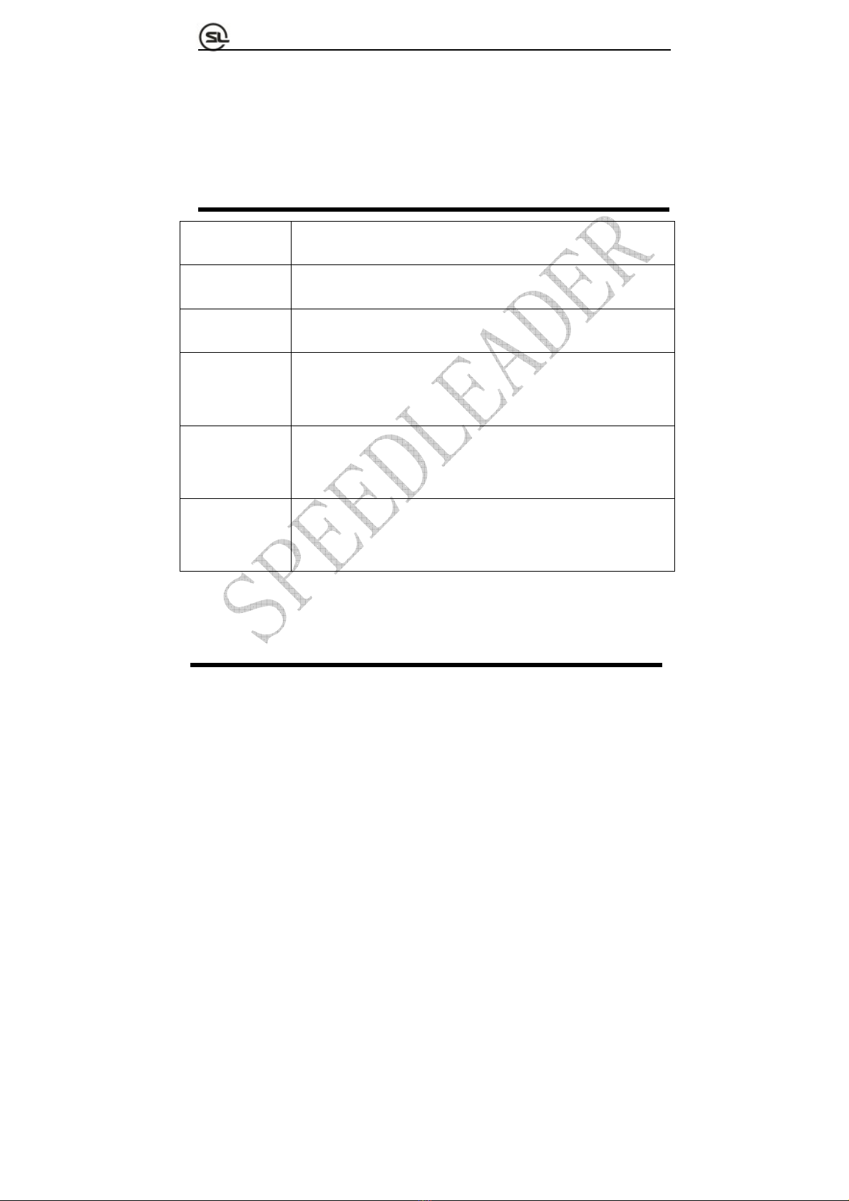
③FUNCTION area
The area comprises BRI, PART, AUTO and PRESET keys.
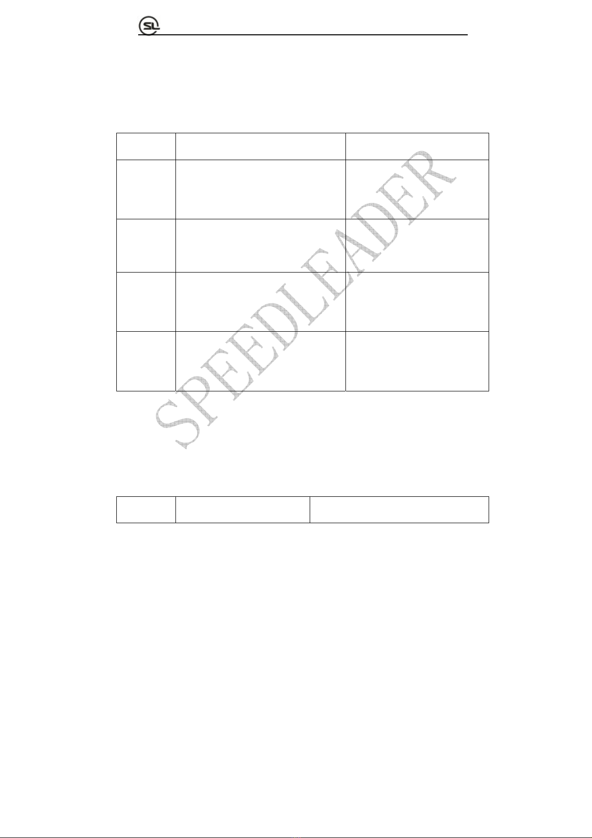
Table 4-1 Functions of BRI, PART, AUTO and PRESET Keys
Descriptions on key function Background light of key
BRI Tap BRI key to enter the shortcut menu and
adjust the brightness of the corresponding
channel by the rotary knob.
The light is on in brightness
shortcut menu.
PART Switch to part or full screen. Part screen: Background light is on.
Full screen: Background light is off.
AUTO Auto calibrate VGA signal of the preview(It
be carried out only when the preview signal
is the VGA and the valid signal)
Background light is on when the
AUTO key is pressed and off after
calibration.
PRESET Enter PRESET mode and press RETURN
or PRESET key to exit the mode.
After entering the PRESET mode,
all channel keys in INPUT area are
on.
④TRANSTION area
The area includes CUT and TAKE keys.
Table 4-2 Functions of CUT and TAKE Keys
Descriptions on key function Background light of key

Page 15 of 53
S
HENZHEN
S
PEEDLEADER TE
C
HN
O
L
O
G
Y
CO
.
,
LTD. LED Vi
deo
Pr
ocesso
r
CUT Directly switching Background light normally is on in default
state; after the key is pressed, the light flashes
once and then normally on.
TAKE Effect switching Background light is normally on in common
state; After the key is pressed, the light flashes
as long as effect setting time.
Effect of CUT and TAKE keys in different modes
Table4-3 EffectofCUTandTAKEKeysinDifferentModes
Switcher mode Splicer mode
FADE Switch between the preview
picture and the program picture
Switch the preview signal to the spliced
picture.
PIP Add the PIP picture on the
program picture.
Add the PIP signal to the spliced picture.
TITLE Key the preview picture and add
the preview picture to the
program picture.
Key the preview signal and add to the spliced
picture.
⑤EFFECT area
The area includes FADE, PIP and TITLE keys which respectively represent three
effect modes of the system: fade, picture-in-picture (PIP) and title. Only one effect mode
can be selected at the same time and the background light of the key indicates the effect
mode of the current system.

Page 16 of 53
S
HENZHEN
S
PEEDLEADER TE
C
HN
O
L
O
G
Y
CO
.
,
LTD. LED Vi
deo
Pr
ocesso
r
In a selected effect mode, press another mode key can switch to the other effect
modes and press the same mode key can open the shortcut menu of the mode itself.
⑥Rotary knob switching area
The rotary knob switching area is precisely the rotary knob with scales. The rotary
knob is to switch the picture effect by rotation. Rotating the knob from zero to full scale
gradually is equal to the effect that the current program picture is faded gradually after the
TAKE key is pressed and the preview picture is switched to the program picture slowly.
Through the rotary knob, the switching between the pictures can be fixed at a specific
intermediate state, thus realizing the switching effect more flexibly.
Note: Rotating the knob to the intermediate state indicates that the picture is switched
to the intermediate state. Tapping TAKE or CUT key can finish the rest switching process.
Now, the current scale of the rotary knob has no effect to the switching state; and only
rotating the knob again can enable the effect of the switch knob.
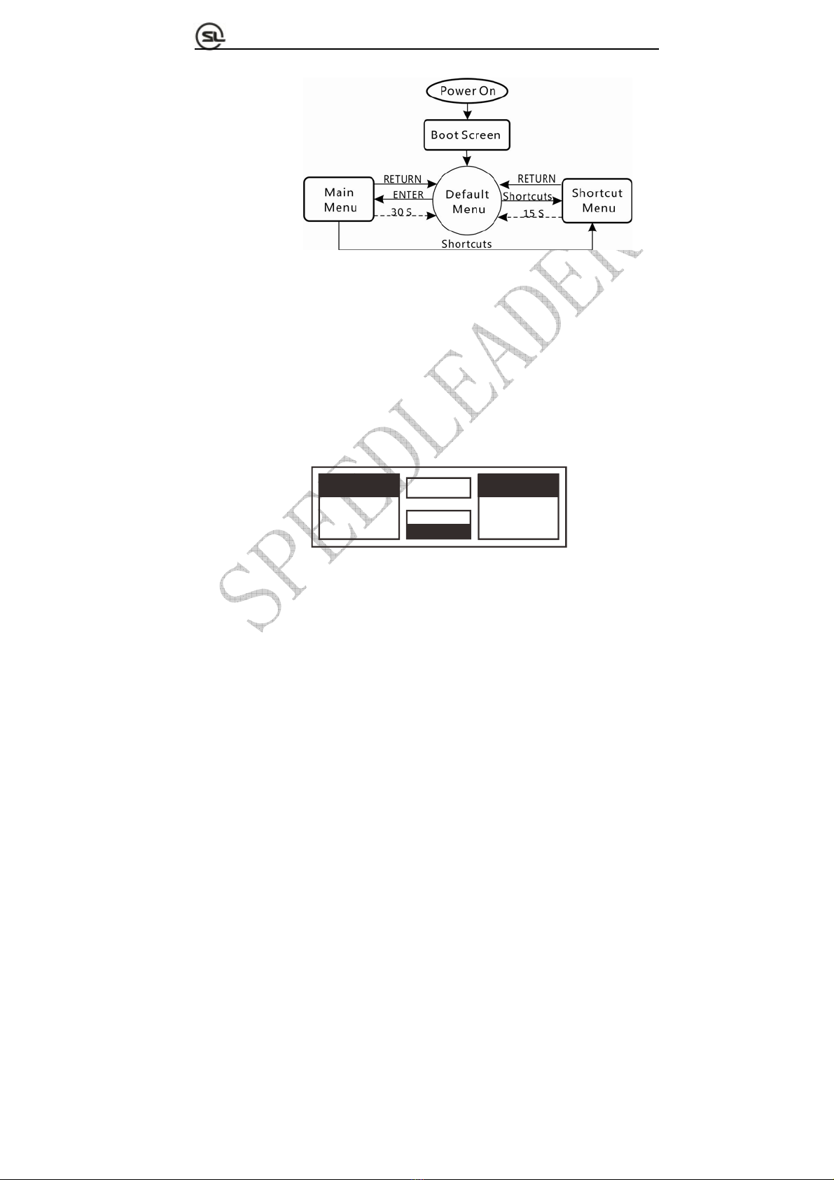
Menu system overview
Startup menu is displayed on the LCD screen in startup process of system after the
system is powered on; after the system is started completely, the default menu is displayed.
If the shortcut menu or main menu is not operated at some time, the menu will return to
the default menu automatically with the flowchart as shown in Fig. 4-2:
Page 17 of 53
S
HENZHEN
S
PEEDLEADER TE
C
HN
O
L
O
G
Y
CO
.
,
LTD. LED Vi
deo
Pr
ocesso
r
Fig. 4-2 Flowchart of System Menu
Default menu introductions
With different splicing methods, the default menu can be divided into two types:
When multi-machine splicing of the LVP6000 is off (refer to descriptions on
multi-machine splicing for more information), the default menu is as shown in Fig. 4-3:
FADE
0.5S
PREVIEW PROGRAM
VGA1 DVI1
1366x768/60 NoSync
0%
Fig. 4-3 Default Menu
The default menu can be divided into four areas, namely, preview area (left part),
program area (right part), switching speed (middle upper part) and effect mode area
(middle lower part).
Preview area:
Display the preview video name and resolution,if no signal in the channel, the third line of
the preview area will display “No Sync”
Page 18 of 53
S
HENZHEN
S
PEEDLEADER TE
C
HN
O
L
O
G
Y
CO
.
,
LTD. LED Vi
deo
Pr
ocesso
r
Program area:
Display the program video name and resolution,if no signal in the channel, the third line of
the program area will display “No Sync”
Switching progress bar:
Reflect the progress of the current switching knob (rotating the switching knob can display
the switching percentage in time).
Effect mode area
Upper line displays the current effect mode (FADE, PIP, and TITLE).
Lower line displays the effect switching time (0-5S).
Note: The effect switching time can be adjusted directly by the knob.
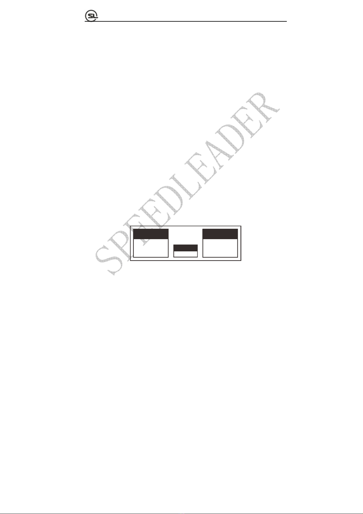
When the multi-machine splicing method of the LVP6000 is on, the default menu is as
shown in the Fig. 4-4:
INPUT OUTPUT
VGA1 A:1920x1080
1366x768/60
SPLICE
B:1920x1080
UnEqual
Fig. 4-4 Default Menu in Multi-machine Splicing Mode
The default menu can be divided into three areas: input area (left part), output area (right
part) and splicing mode area (middle lower part).

Page 19 of 53
S
HENZHEN
S
PEEDLEADER TE
C
HN
O
L
O
G
Y
CO
.
,
LTD. LED Vi
deo
Pr
ocesso
r
Input area:
Display the input video name and resolution
Output area:
Display the resolution of A output and B output.
Splicing mode area:
Display the current splicing mode (equal or unequal).
Main menu introductions
Tapping and rotating the MENU key in the default menu can enter the main menu
interface. Fig. 5-2 shows the first-level menus of the main menu system on the LCD
display screen. There are eight first-level submenus in the main menu, including picture
quality, crop, output, splicing, effect, function, advanced and system. The user can rotate
and tap the MENU key to quickly select and enter the next menus.
IMAGE OUTPUT
CAPTURE SPLICE
EFFECT FUNC
A
DVANCE SYSTEM
Fig. 4-5 First-level Submenus
Main menu involves in the following functions:
This manual suits for next models
3
Table of contents
Other SPEED LEADER DVD Player manuals


