Speeflo PowrTwin 5500DI User manual

0500 © 2000 Titan Tool Inc. All rights reserved. Form No. 313-1602, REV A
Printed in the U. S. A.
Do not use this equipment before reading this manual!
PowrTwin 5500DI
Owner’s Manual
For professional use only
NOTE: This manual contains important warnings
and instructions. Please read and retain for
reference.
Model Number 449-500
NOTE: This manual contains important warnings
and instructions. Please read and retain for
reference.
NOTE: This manual contains important warnings
and instructions. Please read and retain for
reference.
NOTE: This manual contains important warnings
and instructions. Please read and retain for
reference.
NOTE: This manual contains important warnings
and instructions. Please read and retain for
reference.

2©Titan Tool Inc. All rights reserved.
Congratulations on having selected the finest airless sprayer
available in the world. Speeflo piston pumps are tireless
workhorses - so tough they are virtually indestructible, even
under the most severe service. Speeflo designs and builds
equipment with superior quality and reliability. Equipment that
will last for years with minimal maintenance and downtime. This
equipment will make you money year after year. We thank you
for your purchase and welcome you to our large and growing
family of Speeflo users.
The unique ability of this PowrTwin 5500DI to operate with
either gas or electric power provides you with the flexibility to
work indoors or outside where no electricity is available.
Hydraulic drive makes possible the longest stroke and slowest
cycling pumps in the industry which translates into low
maintenance and longer life. Electric units operate quietly with
no motor starting and stopping.
The PowrTwin 5500DI is equipped with Speeflo's exclusive and
patented Severe Service 500™ fluid pump. This technology will
give you significantly longer rod, cylinder, and packing life than
any other sprayer built in the world. This double ball piston
pump employs a dependable and durable time-tested design.
All pumps use an exclusive thick hard chrome plating on rod
and cylinder parts. This patented plating process is harder than
nitralloy, stainless steel, or hard chrome used by any other paint
pump manufacturer and much more abrasion resistant. Highly
polished parts reduce friction, extend packing life, and avoid
damage from corrosion and abrasion. More than 100,000 of
these pumps are in operation around the world.
PowrTwin 5500DI offers other cost saving features:
•Freeze-proof pressure control
•Choice of power — gas, electric, or both
•Tungsten carbide valve seats
•Self-adjusting packings
•Exclusive hand-tight swivel foot valve
•Large capacity inline paint filter
•"Floating Ball" pressure bleed valve
You have made an excellent choice. We know you will be
pleased with your new PowrTwin 5500DI. Thanks again for
selecting Speeflo. We appreciate your business.
PowrTwin 5500DI
Table of Contents
Specifications . . . . . . . . . . . . . . . . . . . . . . . . . . . . . . . . . . . 3
Safety Warnings . . . . . . . . . . . . . . . . . . . . . . . . . . . . . . . 4–7
Operating Components . . . . . . . . . . . . . . . . . . . . . . . . . . . 8
Setup . . . . . . . . . . . . . . . . . . . . . . . . . . . . . . . . . . . . . . . . . . 9
Fueling . . . . . . . . . . . . . . . . . . . . . . . . . . . . . . . . . . . . . . . . 9
Operation . . . . . . . . . . . . . . . . . . . . . . . . . . . . . . . . . . . . . 10
Color Change / Clean Out / Flushing . . . . . . . . . . . . . . . . 11
Maintenance . . . . . . . . . . . . . . . . . . . . . . . . . . . . . . . . . . . 12
Troubleshooting . . . . . . . . . . . . . . . . . . . . . . . . . . . . . 13–15
Airless Spraying . . . . . . . . . . . . . . . . . . . . . . . . . . . . . . . 13
Spray Patterns . . . . . . . . . . . . . . . . . . . . . . . . . . . . . . . . 14
Hydraulic Motors . . . . . . . . . . . . . . . . . . . . . . . . . . . . . . . 15
Fluid Pumps . . . . . . . . . . . . . . . . . . . . . . . . . . . . . . . . . . 15
Parts Lists, Drawings, and Service Instructions . . . . 16–28
Main Assembly — Gas Models . . . . . . . . . . . . . . . . . . . . 16
Power Convertokits . . . . . . . . . . . . . . . . . . . . . . . 17, 18, 19
Cart Assembly . . . . . . . . . . . . . . . . . . . . . . . . . . . . . . . . . 20
Hydraulic System . . . . . . . . . . . . . . . . . . . . . . . . . . . . . . 21
Hydraulic Motor . . . . . . . . . . . . . . . . . . . . . . . . . . . . . 22–24
Fluid Pump . . . . . . . . . . . . . . . . . . . . . . . . . . . . . . . . 24–25
Inlet Accessories . . . . . . . . . . . . . . . . . . . . . . . . . . . . . . . 26
Outlet Accessories . . . . . . . . . . . . . . . . . . . . . . . . . . . 26–28
Accessories & Service Kits . . . . . . . . . . . . . . . . . . . . . . . 29
Warranty . . . . . . . . . . . . . . . . . . . . . . . . . . . . . . . . . . . . . . 32
WARNING: The Engine Exhaust
from this product contains chemicals
known to the State of California to
cause cancer, birth defects, or other
reproductive harm.
U.S. Patents: 3,936,002; 4,220,286;
4,457,472; 4,508,268; 4,494,697;
4,500,119; 4,626,004; 4,611,758;
4,744,571; 4,728,213; 4,768,932;
4,755,638; 4,768,929; 4,840,543;
4,908,538; 5,074,467; 5,425,506

©Titan Tool Inc. All rights reserved. 3
Specifications
Gas Powered Units
Delivery (GPM) 2.0
(LPM) 7.5
Cycle Rate (Gallon) 55
(Liter) 14.5
Cycles per Minute (Maximum) 110
Maximum Tip Size - 1 Gun .043"
Maximum Tip Size - 2 Guns .033"
Maximum Tip Size - 3 Guns .023"
Pressure Range (psi) 400 - 3300
Pressure Range (bar) 28 - 228
Power Honda 5.5 hp, 4-Stroke,
Single Cylinder, Overhead Valve Engine With Oil Alert
Fuel Capacity 0.97 US Gallons
(Approximately 3.5 hours run time)
Halogenated Solvent Compatible Yes
Weight 159 Lbs. (72 Kg.)
Inlet Paint Filter 10 Mesh "Rock Catcher"
Outlet Paint Filter 5 Mesh, 18 in.2
Pump Inlet 3/4" NPT(F)
Pump Outlet 1/2" NPT(F) to Paint Filter
Paint Filter Hose Connections (1) - 1/4" NPSM(M)
(1) - 3/8" NPT(F) Plugged
Dimensions 31" H (787 mm) x 34" L (864 mm) x 23" W (584 mm)
Fluid Pump Wetted Parts Electroless nickel plated ductile iron, electroless nickel plated carbon steel,
proprietary Severe Service 500™ hard chrome anti-wear surface, stainless steel,
tung-sten carbide, PTFE, thiokol impregnated leather, ultra high molecular weight
polyethylene.
Electric Units
AC - Electric DC - Electric
Delivery (GPM) 1.50 1.25
(LPM) 5.70 4.70
Cycle Rate (Gallon) 55
(Liter) 14.5
Cycles per Minute (Maximum) 83 68
Maximum Tip Size - 1 Gun .041" .036"
Maximum Tip Size - 2 Guns .029" .026"
Maximum Tip Size - 3 Guns .021" .019"
Pressure Range (psi) 400 - 3300
Pressure Range (bar) 28 - 228
Power 3 HP Baldor TEFC Motor 2 HP DC Motor
230V, 60 Hz, 12.5 AMP 115V, 15.5 AMP
230V, 50 Hz, 12.9 AMP 230V, 9 AMP
Overload Protected Overload Protected
Halogenated Solvent Compatible Yes
Weight 178 Lbs. (80.7 Kg.)
Inlet Paint Filter 10 Mesh "Rock Catcher"
Outlet Paint Filter 5 Mesh, 18 in.2
Pump Inlet 3/4" NPT(F)
Pump Outlet 1/2" NPT(F) to Paint Filter
Paint Filter Hose Connections (1) - 1/4" NPSM(M)
(1) - 3/8" NPT(F) Plugged
Dimensions 31" H (787 mm) x 34" L (864 mm) x 23" W (584 mm)
Fluid Pump Wetted Parts Electroless nickel plated ductile iron, electroless nickel plated carbon steel,
proprietary Severe Service 500™ hard chrome anti-wear surface, stainless steel,
tungsten carbide, PTFE, thiokol impregnated leather, ultra high molecular weight
polyethylene.

4©Titan Tool Inc. All rights reserved.
Warning Labels
Your sprayer has the English language Warning Label shown on Page 5 in the location indicated below. If you require this label in
French, German, or Spanish, or require additional English labels, order directly from Speeflo free of charge.
Call toll free 1-800-526-5362.
PART # LANGUAGE
313-771 English
313-784
313-1306 Spanish
313-1307
313-785 French
313-786
313-787 German
313-788
1. Honda engines are designed to give safe and dependable
service if operated according to instructions. Read and
understand the Honda Owner's Manual before operating
the engine. Failure to do so could result in personal injury
or equipment damage.
2. To prevent fire hazards and to provide adequate ventilation,
keep the engine at least 1 meter (3 feet) away from
buildings and other equipment during operation. Do not
place flammable objects close to the engine.
3. Children and pets must be kept away from the area of
operation due to a possibility of burns from hot engine
components or injury from any equipment the engine may
be used to operate.
4. Know how to stop the engine quickly, and understand the
operation of all controls. Never permit anyone to operate
the engine without proper instructions.
5. Gasoline is extremely flammable and is explosive under
certain conditions.
6. Refuel in a well-ventilated area with the engine stopped.
Do not smoke or allow flames or sparks in the refueling
area or where gasoline is stored.
7. Do not overfill the fuel tank. After refueling, make sure the
tank cap is closed properly and securely.
8. Be careful not to spill fuel when refueling. Fuel vapor or
spilled fuel may ignite. If any fuel is spilled, make sure the
area is dry before starting the engine.
9. Never run the engine in an enclosed or confined area.
Exhaust contains poisonous carbon monoxide gas;
exposure may cause loss of consciousness and may lead
to death.
10. The muffler becomes very hot during operation and
remains hot for a while after stopping the engine. Be
careful not to touch the muffler while it is hot. To avoid
severe burns or fire hazards, let the engine cool before
transporting it or storing it indoors.
11 Never ship/transport unit with gasoline in tank.
Gasoline Engine Safety/Warnings
DO NOT use this equipment to spray water or acid.
Do not lift by cart handle when loading or unloading.
CAUTION
WARNING

©Titan Tool Inc. All rights reserved. 5
An airless spray gun requires that fluid be
introduced to it at very high pressure.
Fluids under high pressure, from spray or
leaks, can penetrate the skin and inject
substantial quantities of toxic fluid into the
body. If not promptly and properly treated,
the injury can cause tissue death or
gangrene and may result in serious,
permanent disability or amputation of the
wounded part. Therefore, extreme caution
must be exercised when using any airless
spray equipment. IF YOU ARE INJECTED,
SEE A PHYSICIAN IMMEDIATELY! DO
NOT TREAT AS A SIMPLE CUT!
NOTE TO PHYSICIAN: Injection into
the skin is a serious, traumatic injury.
It is important to treat the injury
surgically as soon as possible. Do not
delay treatment to research toxicity.
Toxicity is a concern with some exotic
coatings injected directly into the
bloodstream. Consultation with a
plastic surgeon or a reconstructive
hand surgeon may be advised.
1. Handle the spray gun carefully. Keep
clear of the nozzle. NEVER point the
gun at yourself or anyone else. NEVER
permit any part of your body to come in
contact with the fluid stream of either
the gun or any hose leak. ALWAYS
keep the gun trigger safety lever in a
locked position when not spraying.
ALWAYS use a tip safety guard.
2. NEVER attempt to force the flow of
fluid backward through the gun with
your finger, hand or hand-held object
against the gun nozzle. THIS IS NOT
AN AIR SPRAY GUN.
3. NEVER attempt to remove tip,
disassemble or repair equipment
without first doing the following:
4. Before flushing system, always
remove spray tip and adjust fluid
pressure to lowest possible setting.
5. Tighten all fluid connections before
each use. NEVER exceed 3300 psi
with this unit. Make sure that all
accessory hoses, connections,
swivels and so forth can withstand the
high pressures which develop.
NEVER exceed the pressure rating of
any component in the system.
6. The paint hose can develop leaks
from wear, kinking, abuse, etc. A leak
is capable of injecting fluid into the
skin, therefore the paint hose should
be inspected before each use.
NEVER attempt to plug a hose with
any part of your body, adhesive tape
or any other makeshift device. Do not
attempt to repair a spray hose.
Instead, replace it with a new
grounded hose. Use only with hoses
that have spring guards.
7. Be sure that the airless equipment being
used and the object being sprayed are
properly grounded to prevent static
discharge or sparks which could cause
fire or explosion. Warning: ALWAYS hold
the gun against metal container when
flushing system with tip removed, to
prevent static discharge. CAUTION: To
reduce the risk of electrical shock, do not
expose to rain. Store indoors.
8. ALWAYS keep the working area around
the pump well ventilated. Additionally,
the pump itself should be a minimum of
25' (7.5m) from the spray area. If these
instructions are not followed, there is
the possibility of fire or explosion with
certain materials. ALWAYS follow the
coating or solvent manufacturer's safety
precautions and warnings. Never
spray flammable material near open
flames, pilot lights or any source of
ignition.
9. ALWAYS wear spray masks and
protective eyewear while spraying.
Additional personal protective
equipment may be required depending
on the type of material being sprayed
and conditions of ventilation. Always
contact supplier of material being
sprayed for recommendation.
10. Keep all extension poles clear of
electrical wires.
11. NEVER alter or modify any part of this
equipment; doing so could cause it to
malfunction.
12. NEVER leave equipment unattended.
Keep away from children or anyone
not familiar with the operation of
airless equipment.
GROUNDING INSTRUCTIONS: This
product should be grounded. In the event
of an electrical short circuit, grounding
reduces the risk of electric shock by
providing an escape wire for the electric
current. This product is equipped with a
cord having a grounding wire with an
appropriate grounding plug.The plug must
be plugged into an outlet that is properly
installed and grounded in accordance
with all local codes and ordinances.
DANGER: Improper installation of the
grounding plug can result in a risk of
electric shock.
If repair or replacement of the cord or
plug is necessary, do not connect the
grounding wire to either flat blade
terminal. The wire with insulation having
an outer surface that is green (with or
without yellow stripes) is the grounding
wire. Check with a qualified electrician or
serviceman if the grounding instructions
are not completely understood, or if in
doubt as to whether the product is
properly grounded. Do not modify the
plug provided; if it will not fit the outlet,
have the proper outlet installed by a
qualified electrician.
•This product is for use on a nominal
120-volt circuit and has a grounding
plug that looks like the plug
illustrated below.
•Make sure that the product is
connected to an outlet having the
same configuration as the plug. No
adapter should be used with this
product.
EXTENSION CORDS: Use only a 3-wire
extension cord that has a 3-slot
receptacle that will accept the plug on the
pump. Make sure your extension cord is
in good condition. When using an
extension cord, be sure to use one heavy
enough to carry the current this pump will
draw.
For lengths Use extension
less than: gauge:
50 ft. 14 AWG
100 ft. 12 AWG
150 ft. 10 AWG
An undersized cord will cause a drop in
line voltage resulting in loss of power and
overheating. If in doubt, use the next
heavier gauge. The smaller the gauge
number, the heavier the cord.
PRESSURE RELEASE PROCEDURE
A. Set trigger lock in the locked
position.
B. Shut off pump and unplug
electrical cord.
C. Release fluid pressure from
entire system and trigger gun.
D. Reset trigger lock in the
locked position.
DO NOT USE EQUIPMENT BEFORE READING THIS SECTION
HIGH PRESSURE SPRAY CAN CAUSE SERIOUS INJURY
Maximum Working Pressure 3300 psi, 228 bar
WARNING

6©Titan Tool Inc. All rights reserved.
Una pistola rociadora sin aire requiere que
se le introduzca líquido a presión muy alta.
Los líquidos bajo presión alta, de la
rociadura o de las fugas, pueden penetrar
en la piel e inyectar en el cuerpo cantidades
considerables de líquido tóxico. Si no se
atiende rápida y apropiadamente, la lesión
puede causar muerte del tejido o gangrena,
y puede resultar en incapacidad seria y
permanente o en la amputación de la parte
lesionada. Por lo tanto, hay que emplear
precauciones estrictas al usar cualquier
equipo de rociadura sin aire. SI USTED HA
ESTADO EXPUESTO A LA PENETRACION
DE TOXICOS POR INYECCION,
CONSULTE INMEDIATAMENTE AL
MEDICO. ¡NO TRATE LA HERIDA COMO SI
FUERA UNA MERA CORTADURA!
NOTA PARA EL MEDICO: La penetración
de tóxicos en la piel es una herida seria y
traumática. Es importante tratar la herida
quirúrgicamente lo más pronto posible.
No demore el tratamiento para investigar
la toxicidad. La toxicidad es asunto serio
cuando se trata de la penetración de
ciertos revestimientos tóxicos en la
corriente sanguínea. Puede que sea
necesaria la consulta con un cirujano
plástico o un cirujano especialista en la
reconstrucción de la mano.
1. Maneje la pistola de rociadura con
cuidado. Manténgase alejado de la
boquilla. JAMAS apunte la pistola hacia
usted u otra persona. NUNCA permita
que parte alguna de su cuerpo se
ponga en contacto con el chorro de
líquido de la pistola o de alguna fuga de
la manguera. SIEMPRE mantenga
trabado el seguro de la pistola mientras
no esté rociando. SIEMPRE utilice el
protector de seguridad de la boquilla.
2. JAMAS intente forzar el flujo del líquido
por la pistola hacia atrás con el dedo, la
mano o un objeto sostenido con la
mano contra la boquilla de la pistola, ya
que NO SE TRATA DE UNA PISTOLA
DE ROCIADURA DE AIRE.
3. JAMAS intente quitar la boquilla ni
desarmar o reparar el equipo sin haber
cumplido antes con los pasos siguientes:
4. Antes de lavar el sistema, siempre quite la
boquilla de rociadura y ajuste la presión
del líquido al valor más bajo posible.
5. Ajuste todas las conexiones antes de
cada uso. JAMAS supere 3300 libras
por pulgada cuadrada con esta unidad.
Asegúrese de que todas las mangueras,
conexiones, articulaciones giratorias y
demás elementos accesorios estén en
condiciones de tolerar las altas
presiones que se presentan. JAMAS
exceda la clasificación de presión de
cualquier componente del sistema.
6. ADVERTENCIA: La manguera de
pintura puede presentar fugas como
resultado del desgaste, retorcimiento,
abuso, etc. Las fugas pueden inyectar
líquido a través de la piel, por lo que la
manguera de pintura debe ser
inspeccionada antes de cada uso.
JAMAS intente obturar la manguera con
una parte de su cuerpo o con tela
adhesiva o cualquier otro elemento
improvisado. No intente reparar una
manguera de rociadura; en cambio
reemplácela con una manguera nueva
conectada a tierra. Utilice solamente
mangueras con protector de resorte.
7. Asegúrese de que el equipo sin aire que
esté empleando y el objeto que se intenta
rociar estén correctamente conectados a
tierra para evitar descargas estáticas o
chispas que podrían ocasionar incendio o
explosión. ADVERTENCIA: Sostenga
SIEMPRE la pistola contra el receptáculo
de metal al limpiar el sistema con la
boquilla desprendida, para evitar la
descarga estática. ADVERTENCIA: Para
reducir riesgo de descarga eléctrica, no
exponer a la lluvia.
8. SIEMPRE mantenga el lugar de trabajo
alrededor de la bomba bien ventilado.
Además, la bomba en sí debe estar
ubicada a no menos de 7,6 m de la
operación de rociadura. Si no se observan
estas instrucciones, existe el riesgo de
incendio o explosión con ciertos
materiales. SIEMPRE observe las
precauciones y advertencias de los
fabricantes sobre revestimientos y
solventes. Nunca rocíe material inflamable
cerca de llamas expuestas, llamas piloto o
cualquier fuente de ignición.
9. SIEMPRE use máscaras apropiadas y
anteojos de protección durante la
operación de rociadura. Según el tipo de
material que se está rociando y las
condiciones de ventilación puede ser
necesario usar equipo personal protector
adicional. Siempre comuníquese con el
proveedor del material para conseguir
recomendaciones.
10. Mantenga todas las varas de extensión
fuera del alcance de cables eléctricos.
11. JAMAS altere o modifique parte alguna
de este equipo, ya que ello puede
causar deficiencias de funcionamiento.
12. JAMAS deje al equipo solo. Manténgalo
fuera del alcance de los niños o de
cualquier persona no familiarizada con
la operación de equipo sin aire.JAMAS
use una manguera de menos de 15,2 m
con esta unidad. Almacenar bajo techo.
INSTRUCCIONES PARA LA PUESTA A
TIERRA: Este producto debe conectarse a
tierra. En caso de corto circuito, la conexión a
tierra proporciona una vía de escape para la
corriente eléctrica y reduce el riesgo de
choques eléctricos. El producto está dotado
de un cable provisto de un alambre y de un
enchufe de puesta a tierra. El enchufe debe
enchufarse en un tomacorriente debidamente
instalado y dotado de conexión a tierra, de
acuerdo con las estipulaciones de los códigos
y ordenanzas locales.
PELIGRO: La instalación incorrecta
del enchufe de puesta a tierra podría
crear el riesgo de choque eléctrico.
Si es necesario reparar o re-emplazar el
cordón o el enchufe, no conecte el alambre
de puesta a tierra a ninguna de las dos
terminales de cuchilla plana. El alambre con
aislamiento exterior verde, con o sin rayas
amarillas, es el alambre de puesta a tierra.
Consulte a un electricista o técnico
competente si no comprende bien las
instrucciones para la conexión a tierra o si
tiene dudas de que el producto está
conectado a tierra correctamente. No
modifique el enchufe que viene con el
producto; si no encaja en el tomacorriente,
pida a un electricista competente que instale
el tomacorriente apropiado.
•Este producto ha sido diseñado para
usarse en un circuito de tensión
nominal de 120 voltios y está dotado
de un enchufe de puesta a tierra
semejante a la ilustrada más adelante.
•Asegúrese de que el producto esté
enchufado en un tomacorriente que tenga
la misma configuración del enchufe. No
debe usarse ningún adaptador.
CORDON DE EXTENSION — Use sólo un
cordón de extensión trifilar que tenga un
enchufe de puesta a tierra con tres
cuchillas, y un receptáculo con tres ranuras
que acepte el enchufe que viene con el
producto. Cerciórese de que el cordón de
extensión esté en buen estado. Al usar un
cordón de extensión, cerciórese de que sea
suficientemente grueso para transportar la
corriente que su producto usará.
Para tramos Use cordones
de menos de: de calibre:
15,2 m 14 AWG
30,4 m 12 AWG
45,7 m 10 AWG
Un cordón demasiado corto provocará una
caída de la tensión, ocasionando una
pérdida de potencia y recalentamiento. Si
tiene dudas, use un calibre más grueso.
Cuanto más pequeño sea el número de
calibre, más grueso será el cable.
PROCEDIMIENTO DE
DESCOMPRESION
A. Coloque el seguro de la pistola
en posición trabada.
B. Apague la bomba y desconecte
también el cable de electricidad.
C. Descargue la presión del líquido
de todo el sistema y de la pistola.
D. Vuelva a trabar el seguro.
NO USE EL EQUIPO ANTES DE LEER ESTA SECCION
LA ROCIADURA A PRESION ALTA PUEDE CAUSAR LESION GRAVE.
Presión de Trabajo Máxima 3300 libras por pulgada cuadrada (psi), 228 bar
ADVERTENCIA

©Titan Tool Inc. All rights reserved. 7
Le liquide introduit dans un pistolet
pulvérisateur sans air doit l’être à pression
extrêmement élevée. Les liquides à haute
pression, en provenance du pulvérisateur ou
d’une fuite quelconque, sont capables de
pénétrer la peau et d’injecter d’importantes
quantités de liquide toxique dans l’organisme.
Si elle n’est pas traitée promptement et avec
toute l’attention voulue, la lésion causée de la
sorte peut provoquer la nécrose des tissus ou
la gangrène et donner lieu à de sérieux
handicaps permanents, voire à l’amputation
du membre atteint. Une prudence extrême
s’impose donc lors de l’utilisation de matériel
de pulvérisation sans air. EN CAS
D’INJECTION, CONSULTEZ UN MEDECIN
IMMEDIATEMENT. NE TRAITEZ PAS LA
BLESSURE COMME S’IL S’AGISSAIT
D’UNE SIMPLE COUPURE!
REMARQUE A L’INTENTION DU MEDECIN:
Une injection pénétrant la peau constitue
une lésion traumatique grave qu’il est
important de traiter chirurgicalement
aussitôt que possible. Ne perdez pas de
temps à rechercher la toxicité de
l’injection. Il s’agit là d’un risque à
envisager en cas d’injection directe dans
le circuit sanguin de certains revêtements
exotiques. La consultation d’un chirurgien
plasticien ou d’un spécialiste de la
chirurgie reconstructive de la main peut
être conseillée.
1. Maniez le pistolet avec soin. Maintenez-
vous à l’écart de la buse. N’en dirigez
JAMAIS la buse vers aucune partie de
votre corps ou vers aucune autre
personne. Ne laissez JAMAIS aucune
partie de votre corps entrer en contact
avec le flux de liquide s’échappant du
pistolet ou d’une fuite quelconque au
niveau du flexible. Verrouillez TOUJOURS
le levier de sûreté de la détente lorsque
vous n’êtes pas occupé à pulvériser.
Veillez à TOUJOURS utiliser un dispositif
de sûreté à la buse du pistolet.
2. N’essayez JAMAIS de refouler le flux de
liquide dans le pistolet au moyen de votre
doigt, de votre main ou d’un objet maintenu
contre la buse du pistolet. CET APPAREIL
N’EST PAS UN PISTOLET
PULVERISATEUR A AIR. N’utilisez aucune
pièce de matériel sans air avec une pompe
non équipée d’une soupape de surpression.
3. N’essayez JAMAIS d’enlever la buse, de
démonter ou de réparer l’appareil avant
d’avoir accompli la procédure suivante :
4. Avant de procéder au rinçage du
système, enlevez toujours la buse de
pulvérisation et réglez la pression au
niveau le plus faible possible.
5. Serrez bien tous les raccords du système
hydrodynamique avant chaque emploi. Ne
dépassez JAMAIS, avec cet appareil, une
pression de 3300 psi. Assurez-vous que
tous les flexibles accessoires, raccords,
articulations, etc. sont bien capables de
résister aux hautes pressions prévues. Ne
dépassez JAMAIS la capacité de pression
nominale d’aucun composant du système.
DANGER : Afin de réduire tout risque
d’électrocution, n’exposez pas à la pluie.
6. Des fuites risquent de se produire le long du
flexible de peinture sous l’effet de l’usure,
des torsions, des rudes traitements, etc.
auxquels il est éventuellement soumis. Les
injections de liquide dans la peau sont
possibles par la voie de telles fuites. Il est
donc important d’inspecter le flexible avant
chaque usage. N’essayez JAMAIS d’obturer
une fuite à l’aide de votre doigt ou de tout
autre membre de votre corps, de ruban
adhésif ou de tout autre moyen de fortune.
N’essayez pas non plus de réparer un
flexible de pulvérisation ; remplacez-le plutôt
par un nouveau flexible mis à la terre.
Veillez à n’utiliser que les flexibles munis de
dispositifs de sécurité à ressort.
7. Assurez-vous que le matériel sans air
utilisé et que l’objet à peindre sont
adéquatement mis à la terre, de façon à
éviter toute décharge d’électricité statique
ou toute étincelle susceptible de
provoquer un incendie ou une explosion.
ATTENTION : Tenez TOUJOURS le
pistolet contre un récipient en métal lors
du rinçage du système, après en avoir ôté
la buse. Ne vaporisez JAMAIS de
substances inflammables à proximité de
flammes nues, lampes témoin ni d’aucune
source d’allumage. Rangez à l’intérieur.
8. Le moteur électrique de cet appareil n’est
pas protégé contre les explosions. Il est
donc essentiel d’assurer une bonne
ventilation de la zone de travail et des
alentours de la pompe. Il est également
important de maintenir la pompe à une
distance minimale de 7,6 m de la zone de
pulvérisation. Certains matériaux
présentent, à défaut de suivre ces
consignes, un risque d’incendie ou
d’explosion. Suivez TOUJOURS les
précautions et avertissements du fabricant
de chaque solvant ou revêtement utilisé.
9. Portez TOUJOURS un masque et des
lunettes de protection lors de vos travaux de
pulvérisation. D’autres articles de protection
personnelle peuvent être nécessaires
suivant le type de produit pulvérisé et les
conditions d’aération. Demandez toujours
ses recommandations à votre fournisseur.
10. Maintenez toutes les tiges de rallonge à
distance des fils électriques.
11. N´altérez ou ne modifiez JAMAIS une
partie quelconque de cet appareil, ce qui
pourrait causer des défaillances.
12. Ne laissez JAMAIS le matériel sans
surveillance. Gardez-le hors de portée des
enfants et de toute personne
inexpérimentée quant à l’usage de
matériel sans air.
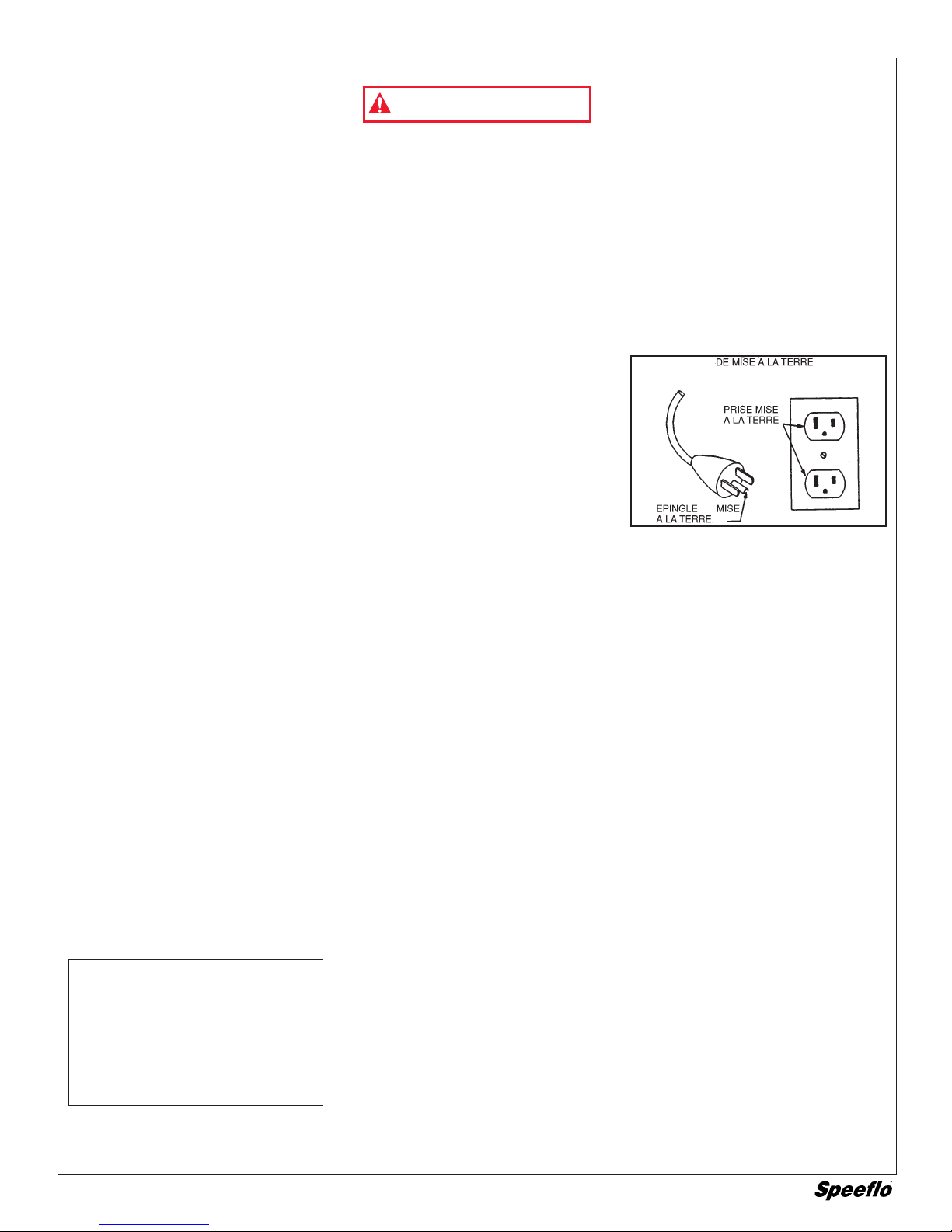
INSTRUCTIONS DE MISE A LA TERRE : Ce
produit doit être mis à la terre. Dans
l’hypothèse d’un court-circuit électrique, la
mise à la terre réduit le risque de chocs
électriques en assurant un fil de fuite pour le
courant électrique. Ce produit est pourvu d’un
cordon possédant un fil de terre avec fiche
appropriée de mise à la terre. La fiche doit
être branchée sur une prise qui est posée et
mise à la terre adéquatement conformément
à tous les codes et règlements locaux.
DANGER: La pose inappropriée de la
fiche de terre peut provoquer un risque
de chocs électriques.
Si le cordon ou la fiche doit être réparé ou
remplacé, ne raccordez pas le fil de terre à
l’une ou l’autre borne à lame plate. Le fil
possédant une isolation dont la surface
extérieure est verte (avec ou sans rayures
jaunes) est le fil de terre. Consultez un
électricien ou un technicien de service
compétent si vous ne comprenez pas
parfaitement les instructions de mise à la terre
ou si vous ne pouvez affirmer avec certitude
que le produit est dûment mis à la terre. Ne
modifiez pas la fiche fournie ; si elle ne rentre
pas dans la prise, faites poser la prise
appropriée par un électricien compétent.
•Ce produit est destiné à être utilisé sur
un circuit à tension nominale de 120
volts et a une fiche de terre qui
ressemble à la fiche illustrée ci-après.
•S’assurer que le produit est branché sur
une prise ayant la même configuration
que la fiche. Aucun adaptateur ne doit
être utilisé avec ce produit.
CORDONS DE RALLONGE - Utilisez
uniquement un cordon de rallonge à trois fils
pourvu d’une fiche de mise à la terre à trois
lames, et une prise à trois fentes qui
acceptera la fiche de la pompe. Assurez-
vous que votre cordon de rallonge est en
bon état. Lorsque vous utilisez un cordon de
rallonge, veillez à en utiliser un
suffisamment puissant pour transporter le
courant que consommera cette pompe.
Pour les longueurs Utilisez une
de moins de rallongede calibre
15,2 m 14 AWG
30,4 m 12 AWG
45,7 m 10 AWG
Un cordon sous-calibré provoquera une chute
de tension secteur ayant pour conséquences
une perte de puissance et une surchauffe. En
cas de doute, utilisez le calibre immédiatement
plus puissant. Plus le numéro de calibre est
bas, plus le cordon est puissant.
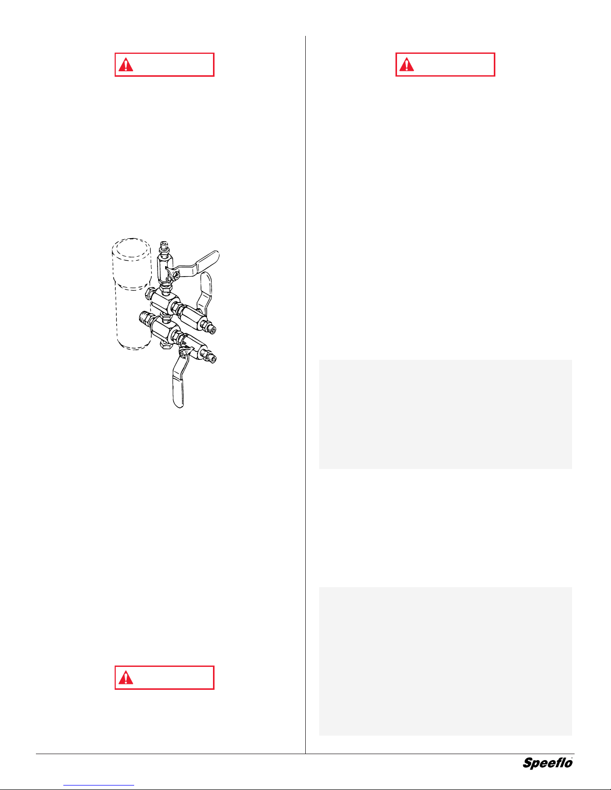
PROCEDURE DE DELESTAGE
DE PRESSION
A. Verrouillez la sûreté de la détente.
B. Arrêtez la pompe et débranchez le
cordon électrique.
C. Délestez la pression dans tout le
système et appuyez sur la détente
du pistolet.
D. Reverrouillez la sûreté de la détente.
NE PAS UTILISER LE MATERIEL AVANT D’AVOIR LU CETTE SECTION
LES PULVERISATEURS A HAUTE PRESSION PEUVENT PROVOQUER
DE SERIEUSES LESIONS
Pression de travail maximale: 3300 psi — 228 bar
AVERTISSEMENT

8©Titan Tool Inc. All rights reserved.
Hydraulic
Motor
Paint Filter
Bleed Line
Fluid Pump
Siphon Tube
Inlet Screen
Hose Rack
Elevator
Elevator
Carriage
Hydraulic Return
Hose
Hydraulic Fluid
Fill and Dipstick
Hydraulic Pressure
Hose
Gas Tank
Muffler
Choke
Air Filter
Operating Components

©Titan Tool Inc. All rights reserved. 9
Set Up
Read, understand, and follow all warnings before starting
or operating this sprayer.
Required tools: Crescent Wrench
1. One Gun Operation - Attach the gun and hose. Always use a
spray hose at least 50 feet long. Do not use PTFE or thread
sealant on this assembly. Do not install the spray tip at this
time.
2. Two Gun Operation - Remove the plug from the second
gun outlet. Connect a hose and a gun to the outlet.
3. Multiple Gun Operation - The PowrTwin 5500DI is
engineered to handle up to 3 guns with .023" tips. When
using more than two guns, make sure the second gun
hookup outlet is plugged. Connect the multiple gun
manifold to the single gun outlet. These manifolds are for
either 2, 3, or 4-guns and have shut off valves. Connect a
hose and gun to each outlet.
4. Fill the wet-cup 1/2 full with Speeflo's Piston Lube (P/N
700-925) supplied by the factory. This extends packing life.
5. Electric Models - Use a 20 amp service outlet. Always
locate the AC electric model within 10 to 15 feet of the
service outlet. Use a short electric cable and a long paint
hose. Any extension cord will create some voltage drop.
For both AC and DC models, if an extension cord is
necessary, use only grounded 3 wire # 12 wire.
If the unit is being operated in an area that is overloaded
by other appliances or low voltage conditions, it is
important to start the unit "unloaded." Tip the electric motor
forward so that the belt is loosened and the motor starts
without full load. This reduces the amperage draw on
starting and may avoid kicking out the circuit breaker.
6. Be sure the PowrTwin system is grounded. All Speeflo
units are equipped with a grounding lug. A grounding cable
(not supplied) should be used to connect the unit to a true
earth ground. Check your local electrical regulations for
detailed grounding instructions. See the Accessories and
Service Kits section near the back of this manual for
ordering information.
8. Strain all paints with Speeflo 5 gallon Nylon Strainer (P/N
160-524) or Speeflo 1 gallon Nylon Strainer (P/N 160-124)
to assure trouble free operation and freedom from frequent
cleaning of inlet screen and gun strainer.
Proper grounding is important. This applies to both gas
and electric powered models. The passage of some
materials through the nylon fluid hose will build up a static
electric charge, which if discharged, could ignite solvent
vapors present and create an explosion.
Fueling
Gasoline is extremely flammable and is explosive under
certain conditions.
•ALWAYS turn the engine off before refueling.
•Refuel in a well-ventilated area.
•Do not smoke or allow flames or sparks in the refueling
area or where gasoline is stored.
•Do not overfill the fuel tank. After refueling, make sure the
tank cap is closed properly and securely.
•Be careful not to spill fuel when refueling. Spilled fuel or
fuel vapor may ignite. If any fuel is spilled, make sure the
area is dry before starting the engine.
•Avoid repeated or prolonged contact with skin or breathing
of vapor.
•Keep out of the reach of children.
Specifications
•Use automotive gasoline that has a pump octane number
of 86 or higher, or that has a research octane number of 91
or higher.
•Unleaded fuel produces fewer engine and spark plug
deposits and extends the life of exhaust system
components.
•Never use stale or contaminated gasoline or an oil/gasoline
mixture. Avoid getting dirt, dust or water in the fuel tank.
Use of a lower octane gasoline can cause persistent
"pinging" or heavy "spark knock" (a metallic rapping noise)
which, if severe, can lead to engine damage.
Gasolines Containing Alcohol
If you decide to use a gasoline containing alcohol (gasohol), be
sure its octane rating is at least as high as that recommended
by the engine manufacturer. There are two types of "gasohol":
one containing ethanol, and the other containing methanol. Do
not use gasohol that contains more than 10% ethanol. Do not
use gasoline containing methanol (methyl or wood alcohol) that
does not also contain co-solvents and corrosion inhibitors for
methanol. Never use gasoline containing more than 5%
methanol, even if it has co-solvents and corrosion inhibitors.
NOTE: Fuel system damage or engine performance
problems resulting from the use of fuels that
contain alcohol is not covered under the
warranty. The engine manufacturer cannot
endorse the use of fuels containing methanol
since evidence of their suitability is incomplete at
this time.
Before buying gasoline from an unfamiliar station,
try to find out if the gasoline contains alcohol. If
it does, confirm the type and percentage of
alcohol used. If you notice any undesirable
operating characteristics while using a gasoline
that contains alcohol, or one that you think
contains alcohol, switch to a gasoline that you
know does not contain alcohol.
NOTE: If "spark knock" or "pinging" occurs at a steady
engine speed under normal load, change brands
of gasoline. If spark knock or pinging persists,
consult your authorized Honda dealer. Failure to
do so is considered misuse, and damage
caused by misuse is not covered by Honda's
Limited Warranty.
Occasionally you may experience light spark
knock while operating under heavy loads. This
is no cause for concern, it simply means your
engine is operating efficiently.
WARNING
WARNING
WARNING

10 ©Titan Tool Inc. All rights reserved.
Operation
Operating the Elevator Carriage
The elevator carriage lowers the motor pump and siphon tube
assembly into the paint bucket. The carriage has three positions:
#1: Raise the elevator carriage to position #1 to allow placing
of the paint bucket underneath the motor pump and siphon
tube assembly.
#2: Secure the elevator carriage in position #2 when
transporting the unit. Position #2 can also be used for
partial submersion of the siphon tube into the paint bucket.
#3: Lower the elevator carriage to position #3 for complete
submersion of the siphon tube into the paint bucket.
Do not tilt the cart back or attempt to move the sprayer
when the elevator carriage is in position #3. This may
damage the inlet screen and siphon tube.
The elevator carriage is under a spring load when it is in
position #3 and may move up very fast after releasing the
locking pin. Keep head clear of the area directly above the
elevator carriage.
Use the following procedure to raise and lower the elevator
carriage.
1. Holding the handle grip with one hand, pull the locking pin
out of the locking hole on the elevator with the other hand.
This allows the elevator carriage to move up and down.
2. Let go of the locking pin once it is free of the locking hole.
3. Move the elevator carriage to the desired position. The
locking pin is spring loaded and will automatically engage
the locking hole on the elevator at the new position.
Startup
1. Areas must be well ventilated to prevent hazardous
operation with volatile solvents or exhaust fumes.
If lacquer or other flammable materials are to be sprayed,
ALWAYS locate the unit outside the immediate spraying
area. Failure to do so may cause an explosion.
2. Locate the unit outside the immediate spraying area to
avoid clogged air intake of the engine or electric motor with
overspray.
3. Before starting the unit, check oil levels.
a. The hydraulic fluid level should read "Full" on the dipstick.
CHECK IT REGULARLY. See “Hydraulic System” in the
Maintenance section of this manual for changing or adding
hydraulic fluid. Do not overfill. Use only Speeflo Coolflo™
Hydraulic Fluid (P/N 430-361).
b. The gasoline engine oil level is determined by the
manufacturer. Check the manufacturer's service manual
supplied.
Use of Speeflo's Coolflo™ Hydraulic Fluid is mandatory in
the PowrTwin 5500DI hydraulic system. Do not use any
other hydraulic fluid. Use of any other hydraulic fluid may
seriously damage hydraulic system and will void warranty.
4. Open the orange handle shut-off valve located on the
hydraulic pressure hose. Handle should be in line with
hose. The figure below shows the handle in the open
position.
5. Turn the pressure control knob counterclockwise (as
viewed from top) to its lowest pressure setting.
6. Open the pressure bleed valve by turning it
counterclockwise. This relieves pressure.
Pressure Bleed
Valve
Pressure Control
Knob
Shut-Off Valve
CAUTION
WARNING
Elevator
Carriage
Handle Grip
Locking Pin
Elevator
Locking
Holes
CAUTION
Paint Bucket
(for reference)
Siphon Tube
Motor Pump
Inlet Screen
Position #1
Position #2
Position #3
CAUTION

©Titan Tool Inc. All rights reserved. 11
a. Your new sprayer was tested at the factory with mineral
spirits. You must clean the system before spraying to
avoid contamination of the sprayed material.
If you are spraying a water based latex, flush with warm,
soapy water followed by a clean water rinse. If you are
using any other coating, flush with warm, soapy water
followed by a solvent. Check with the material
manufacturer for a compatible solvent. Place siphon
tube assembly into proper solvent or water.
b. Place waste container below bleed line.
c. Start engine or electric motor. Turn the pressure control
adjustment knob clockwise (increasing pressure) until
pump cycles evenly and solvent flows freely from bleed
line.
d. Close the pressure bleed valve by turning it clockwise.
This allows the system to pressurize. Hold the gun
trigger open, without spray tip attached, until the fluid
flows smoothly.
7. Repeat above starting procedure with paint material. Lock
gun trigger and attach spray tip. Refer to the spray gun’s
Technical Data Sheet or Owner's Manual for tip installation
and selection of the proper tip size.
8. Test spray pattern. Operate the pump at the lowest hydraulic
pressure which provides good atomization. See the
Troubleshooting section in this manual if you are not getting
the proper pattern.
9. Operating pressure is adjustable from 400 to 3300 psi (228
bar) by turning the pressure control knob clockwise. Do
not turn the knob clockwise more than necessary to
provide satisfactory atomization. Excess pressure wears
out spray tips.
10. When restarting the unit, reduce the pressure at the
pressure control adjustment knob and the pressure bleed
valve.
Color Change/Clean Out/Flushing
Special cleanup instructions for use with flammable
solvents:
•Always flush spray gun at least one hose length from
spray pump.
•If collecting flushed solvents in a one gallon metal
container, place it into an empty five gallon metal
container, then flush solvents.
•Area must be free of flammable vapors.
•Follow all cleanup instructions.
Pressure Relief Procedure
Always reduce pressure when you are cleaning a clogged
tip, changing a tip, servicing any part of the system, or
shutting down. Follow the steps below:
1. Engage the gun trigger lock.
2. Shut off the power source.
3. Close the orange handle shut-off ball valve on the hydraulic
pressure hose.
4. Open the pressure bleed valve by turning it
counterclockwise at least three full turns.
5. Disengage the gun trigger lock and hold trigger open until
flow of material stops.
6. Be certain to hold a metal part of the gun firmly to the side
of a grounded metal container.
Cleaning a Clogged Tip
1. Follow the “Pressure Relief Procedure” above.
2. If tip clogs, rotate tip handle 180° until arrow on handle is
facing the opposite of spray direction and clicks in reverse
position.
3. Trigger gun once so that the pressure can blow the clog
out. NEVER use the tip in the reverse position for more
than ONE trigger pull at a time. This procedure can be
repeated until the tip is free of clogging.
The flow from the spray tip is at very high pressure.
Contact with any body part may be dangerous. Do not
place finger on gun outlet. Do not point the gun at any
person. Never operate the spray gun without the proper tip
guard.
Color Change/Clean Out
Use only compatible solvents when cleaning out oil based
enamels, lacquers, coal tar, and epoxies. Check with the
fluid manufacturer for the recommended solvent.
1. Reduce pressure by turning the pressure control knob and
the pressure bleed valve on the bleed line
counterclockwise. Follow the “Pressure Relief Procedure”
above. The pressure bleed valve should be turned
counterclockwise at least three full turns.
2. Pull siphon tube out of material container.
3. Remove spray tip from gun. Hold gun trigger open until
material flow stops.
4. Put siphon tube into wash solvent or water as applicable,
and operate pump slowly at low pressure until solvent flows
freely from pressure bleed valve line.
5. Close pressure bleed valve and hold gun trigger open until
solvent flows freely from gun. If solvent is not too dirty,
recirculate it by flowing gun stream back into solvent
container. Use additional clean solvent and repeat
procedure if necessary.
6. Check gun strainer screen and pump outlet filter screen
daily. Use 50 mesh screens with spray tip size .015 and
larger. Use 100 mesh screens with spray tip sizes .013 and
smaller.
7. Replace paint filter cap to maximum clockwise rotation.
The filter cover should be hand removable after the first or
second use with new PTFE o-ring.
IMPORTANT: O-Ring must have PTFE backup washer
to seal properly.
8. If unit has been spraying a water soluble material, flush
with water and then repeat procedure with mineral spirits or
Varsol solvent.
9. Wash spray tip in solvent. Blow tip clean with air pressure
directed through the tip in the reverse direction.
Pressure Bleed
Valve
CAUTION
WARNING
WARNING
WARNING

12 ©Titan Tool Inc. All rights reserved.
Maintenance
Hydraulic System
Use of Speeflo's Coolflo™ Hydraulic Fluid is mandatory in
the PowrTwin 5500DI hydraulic system. Do not use any
other hydraulic fluid. Use of any other hydraulic fluid may
seriously damage hydraulic system and will void warranty.
1. Check the hydraulic fluid daily. It should read "Full" on the
dipstick. If it is low, add only Speeflo Coolflo™ Hydraulic Fluid
(P/N 430-361). Never add or change hydraulic fluid except in
a clean dust free area. Contamination of the hydraulic fluid
will shorten hydraulic pump life and may void warranty.
2. Change the hydraulic fluid every six months. Drain old fluid
from tank and fill with 5 quarts of Speeflo Coolflo™
Hydraulic Fluid. Start operation of the system at just
enough pressure to operate the fluid pump. Run the
system at this low pressure for at least 5 minutes. This
removes air from the system. Check the fluid level after this
procedure.
3. The hydraulic system has an external replaceable hydraulic
filter. Change the filter every six months.
4. The hydraulic pump should not be serviced in the field. If
service on the hydraulic pump is required, it must be
returned to Speeflo.
General Fluid Pump Maintenance
If the paint pump is going to be out of service for an extended
period of time, it is recommended that following cleanup a
kerosene and oil mixture be introduced as a preservative.
Packings may tend to dry out from lack of use. This is
particularly true of the upper packing set for which upper
packing lubricant, Piston Lube (P/N 700-925), is recommended
in normal usage. A sample of Lubrisolv accompanies each new
unit. Do not substitute water or paint solvent for Lubrisolv.
Ordinary oil may contaminate the paint material and is not
recommended.
If the paint pump has been out of service for an extended
period of time, it may be necessary to prime the suction by
pouring some of the paint solvent into the inlet siphon tube to
restart. It is extremely important that the threads on the inlet
siphon hose coupling are properly sealed. Any air leakage will
produce erratic operation of pump and may damage the
system. The up and the down strokes should be approximately
equal in time. That is, one should not be faster than the other. A
fast up or down stroke may indicate air in the system or
malfunctioning valve or seats. See the Troubleshooting section.
Hydraulic Motor and Fluid Pump
Service
See the Hydraulic Motor Service Instructions section near the
back of this manual for maintenance and service instructions on
the reciprocating hydraulic motor.
See the Fluid Pump Service Instructions section near the back
of this manual for maintenance and service instructions on the
fluid pump.
Basic Engine Maintenance
•For detailed engine maintenance and technical
specifications refer to the separate Honda engine manual.
•All service to the engine should be performed by an
authorized Honda Power Equipment dealer. To locate a
dealer in your area, look in the Yellow Pages of your
telephone directory under Gasoline Engines, Garden &
Lawn Equipment & Supplies, Lawnmowers, etc.
•The Honda engine is warranted exclusively by American
Honda Motor Co., Inc.
•Use a premium quality motor oil certified to meet or exceed
U.S. Automotive requirement SG.SF/CC.CD. SAE 10W30
is recommended for general all temperature use. Other
viscosities may be required in other climates.
•Use only a (NGK) BP6ES or BPR6E spark plug. Gap the
plug to 0.028 to 0.031 In. (0.7 to 0.8 mm) Always use a
spark plug wrench.
DAILY: Check engine oil level. Fill as necessary. Check
gasoline level. Fill as necessary.
Always follow the fueling procedure outlined earlier in this
manual.
FIRST 20 HOURS: Change engine oil.
EVERY 100 HOURS: Change engine oil.
WEEKLY: Remove the air filter cover and clean the element. In
very dusty environments, check the filter daily. Replace the
element as needed. Replacement elements can be purchased
from your local Honda dealer.
Engine Operation and Service
1. Clean and oil air filter pad on gasoline engine every 25
hours or once weekly. Do not permit the air intake screen
around the fly wheel of the gas engine to load up with paint
or trash. Clean it regularly. The service life and efficiency of
the gas engine model depends upon keeping the gasoline
engine running properly. Change the oil in the engine every
100 hours. Failure to observe this may result in engine
overheating. Consult the engine manufacturer's service
manual provided.
2. To conserve fuel, service life, and efficiency of the unit
always operate the gasoline engine at the lowest RPM at
which it runs smoothly without laboring and delivers the
amount required for the particular painting operation.
Higher RPM does not produce higher working pressure.
The gasoline engine is connected to the hydraulic pump by
a pulley combination designed to produce full paint delivery
of 2.0 GPM at 3600 RPM.
3. The warranty on gasoline engines or electric motors is
limited to the original manufacturer.
If electric motor overloads and stops running,
IMMEDIATELY turn the motor off and follow the Pressure
Relief Procedure outlined earlier in this manual. Wait until
the motor cools (approximately 30 minutes). Then push in
the bubble top, manual reset button, turn the motor on and
pressurize the system.
For CSA approved units only:
The ON / OFF switch is also the RESET!
WARNING
WARNING
Hydraulic Fluid
Fill and Dipstick
CAUTION

©Titan Tool Inc. All rights reserved. 13
Airless Tip Selection
REMEDY
1. Inspect connections for
air leaks
2. Disassemble and clean
3. Inspect and adjust
4. Inspect and replace
1. Replace
2. Adjust
3. Clean
1. Check fluid supply
2. Clean
3. Replace
PROBABLE CAUSE
1. Air in system
2. Dirty gun
3. Needle assembly out of adjustment
4. Broken or chipped seat
1. Worn or broken needle & seat
2. Needle assembly out of adjustment
3. Dirty gun
1. No paint
2. Plugged filter or tip
3. Broken needle in gun
PROBLEM
Spitting gun
Gun will not shut off
Gun does not spray
Troubleshooting Airless Gun
Tips are selected by the orifice size and fan width. The proper selection is determined
by the fan width required for a specific job and by the orifice size that will supply the
desired amount of fluid and accomplish proper atomization.
For light viscosity fluids, smaller orifice tips generally are desired. For heavier
viscosity materials, larger orifice tips are preferred. Please refer to the chart below.
The following chart indicates the most common sizes and the appropriate materials to
be sprayed:
.011 - .013 Lacquers & Stains 100 Mesh Filter
.015 - .019 Oil & Latex 50 Mesh Filter
.021 - .026 Heavy Bodied Latex & Blockfillers 5 Mesh Filter
Fan widths measuring 8" to 12" (20 to 30 cm) are most preferred because they offer
more control while spraying and are less likely to plug.
NOTE: Do not exceed the pump's recommended tip size.

14 ©Titan Tool Inc. All rights reserved.
CONDITION POSSIBLE CAUSE CORRECTION
TAILS Inadequate fluid delivery. Fluid not atomizing correctly.
Increase fluid pressure.
Change to smaller tip orifice size. Reduce fluid
viscosity. Reduce hose length.
Clean gun and filter(s).
Reduce number of guns using pump.
HOUR GLASS Inadequate fluid delivery. Same as above.
DISTORTED Plugged or worn nozzle tip. Clean or replace nozzle tip.
PATTERN EXPANDING & Suction leak. Inspect for suction hose leak.
CONTRACTING (SURGE)
Pulsating fluid delivery Change to a smaller tip orifice size.
Install pulsation dampener in system
or drain existing one. Reduce number of
guns using pump.
Remove restrictions in system; clean
tip screen if filter is used.
ROUND PATTERN Worn tip. Replace tip.
Fluid too heavy for tip. Increase pressure.
Thin material.
Change nozzle tip.
Troubleshooting Guide: Spray Patterns

CONDITION POSSIBLE CAUSE CORRECTION
Oil motor stalls at bottom. Fluid pump piston seat unthreaded. If connecting rod is okay, remove cylinder head plug and pop valve down. Replace plug and start
(No unusual heat problems.) machine. If machine cycles up and stops at bottom again, then problem is piston seat on fluid pump.
Check piston seat. Repair or replace as necessary. If piston seat is okay and problem does not change,
check oil motor.
Valve sticking or oil motor trip rod shifter Remove valve and check for scratches and rough movement when sliding it up and down. Replace
assembly separated. valve and spool in this condition. Check trip rod for possible separation.
and spool in this condition. Check trip rod for possible separation.
Oil motor stalls at top. Valve sticking. Remove valve and check for scratches and rough movement when sliding it up and down. Replace
(No unusual heat problems) valve and spool in this condition.
Broken spring retainer (valve rod Replace valve rod assembly.
assembly)
Broken spring or valve rod. Replace valve rod assembly.
Air in hydraulic motor. Reset Valve.
Purge Air, generally accomplished by low pressure cycling of motor/pump assembly for 5 - 10 minutes.
Check for causes of air introduction.
• Loose fittings in tank.
• Loose fittings on hydraulic pump.
• Loose hose connections.
• Low oil in reservoir.
Air in fluid pump. Stall at top can occur randomly when fluid pump picks up air. Reset valve. Avoid air in the fluid pump.
Low pressure (okay on Blown piston seal. Before dismantling oil motor, start machine. With pump cycling under pressure, touch the hydraulic
down stroke, sluggish on cylinder and the head to see if cylinder or head gets hotter. This will help determine if piston seal.
up.stroke - high heat) is blown or piston nut is broken. If heat is on the head, check the O-Rings on spool valve.
Note: Engine labors on
upstroke, idles back at stall
on the down stroke.
Cracked piston. Dismantle oil motor and check piston seals cylinder bore and piston nut. Pay special attention to piston
nut. It can be cracked and not show externally.
Low pressure (both strokes Blown center O-Rings on spool valve. Before dismantling oil motor, start machine. With pump cycling under pressure, touch the head to see if
- high heat) the head becomes hotter. This will help determine if center O-Ring is blown on spool valve. If hot,
Note: Engine labors at stall remove and replace O-Ring.
on both strokes
Bad hydraulic pump. Replace hydraulic pump.
Troubleshooting Guide: Hydraulic Motors
©Titan Tool Inc. All rights reserved. 15
Troubleshooting Guide: Fluid Sections
CONDITION POSSIBLE CAUSE CORRECTION
Pump delivers on upstroke only or Lower foot valve ball is not seating due to Remove foot valve assembly. Clean and inspect. Test foot valve by filling with
goes up slowly and down fast. trash or wear. water; if ball fails to seal the seat, replace ball.
(Commonly called downstroke dive.)
Material too viscous to siphon. Thin material - contact manufacturer for proper thinning procedures.
Air leaking in on siphon side or damaged siphon Tighten all connections between pump and paint container. If damaged, replace.
hose. Siphon may be too small for heavy material Switch to larger diameter siphon set.
Pump delivers on down stroke only Upper ball is not seating due to trash or wear. Check upper seat and ball with water. If ball fails to seal, replace seat.
.or goes up fast and down slowly
Lower packing set is worn. Replace packing set if worn.
Pump moves up and down fast, Material container is empty or material is too thick Refill with new material. If too thick, remove siphon hose and immerse pump or not
delivering material. to flow through siphon hose add thinner to material. Change to bigger siphon set. Open bleed valve to .
remove air and restart pump.
Bottom ball stuck to foot valve seat. Remove foot valve. Clean ball and seat.
Siphon hose is kinked or loose. Straighten.
Pump moves up and down slowly Loose connections. Bleed valve is open partially or Check all connections between pump and gun. Tighten as necessary. If material
when spray gun is shut off. bleed valve is worn. Lower packing seat is worn. is flowing from bleed hose, close bleed valve or replace if necessary. Should
none of the above be evident, replace lower packing.
Upper and/or lower ball not seating. Reseat balls by cleaning.
Not enough fluid pressure at gun. Spray tip is worn. Replace.
Outlet filter or gun filter is clogged Clean or replace filter.
Low voltage and/or inadequate amperage. Check electrical service. Correct as required.
Hose size or length is too small or too long. Increase hose size to minimize pressure drop through hose and/or reduce hose
length.
Pump chatters on up or down stroke Solvent has caused upper packing to swell. Replace packing.

1
2
3
5
6
4
16 ©Titan Tool Inc. All rights reserved.
Item Part # Description
1449-050 Motor/Pump Assembly
2930-511 Filter Assembly, Outlet Manifold
3451-050 Cart Assembly
4451-060 Elevator
5---------- Hydraulic System
6506-130 Convertokit, 5.5 HP, Honda, Gasoline
Parts Lists, Drawings, and Service Instructions
Major Components — Gas Models

©Titan Tool Inc. All rights reserved. 17
Gas Convertokits (P/N 506-130)
Item Part # Description Quantity
1860-552 Screw...............................................4
2860-004 Flat washer ......................................8
3980-331 Engine, gas 5.5 HP, Honda .............1
4 980-307 Key...................................................1
5980-106 Pulley ...............................................1
6449-103 Mounting plate, gas eng. .................1
7860-502 Stop nut ...........................................4
8449-181 Belt, "V" (not shown) ........................*
*Not part of this assembly
4
6
3
1
2
5
7
2
AC — Electric Convertokit
506-249 506-248
Item Part # Description Qty.Qty.
1860-501 Stop nut...............................6 ...............6
2860-002 Lock washer........................6 ...............6
3860-004 Flat washer.........................12 .............12
4978-382 Motor, electric, 3 HP
60 Cycle, 220 V...................1
978-374 Motor, electric, 3 HP
50 Cycle, 220 V.....................................1
5449-180 Pulley ..................................1
449-178 Pulley ....................................................1
6449-121 Mounting plate, elec. motor,
3 HP ....................................1 ...............1
7860-552 Screw, HH ...........................4 ...............4
8 590-411 Spacer.................................4 ...............4
9860-544 Screw, HH ...........................2 ...............2
10 590-068 Handle grip..........................1 ...............1
11 335-017 Handle.................................1 ...............1
12 449-181 Belt, "V" (not shown) ...........* ................*
*Not part of this assembly
5
6
7
3
3
4
1
2
8
3
2
1
9
10
3
11

18 ©Titan Tool Inc. All rights reserved.
506-211 506-205 506-210
115V CSA, 115V 220V
Item Part # Description Qty.Qty.Qty.
1 506-259 Cover ......................................................................1 ................1 ...............1
2860-501 Nut stop ..................................................................4 ................4 ...............4
3860-002 Lock washerk..........................................................4 ................4 ...............4
4860-004 Flat washer .............................................................8 ................8 ...............8
5449-192 Motor shaft shield ......................................................................1
6 860-535 Screw......................................................................2 ................2 ...............2
7506-257 Circuit breaker reset ...............................................1..................................1
8506-260 ON/OFF switch .......................................................1..................................1
506-261 ON/OFF switch, CSA approved ................................................1
9978-350 Motor, DC-Electric, 2 HP, 50 / 60 Hz, 115 V...........1
978-384 Motor, DC-Electric, 2 HP, 50 / 60 Hz, 115 V
CSA approved ...........................................................................1
978-351 Motor, DC-Electric, 2 HP, 50 / 60 Hz, 220 V...............................................1
10 977-228 Pulley ......................................................................1..................................1
977-225 Pulley.........................................................................................1
11 590-068 Handle grip .............................................................1 ................1 ...............1
12 335-017 Handle ....................................................................1 ................1 ...............1
13 860-552 Screw......................................................................2 ................2 ...............2
14 449-170 Mount plate .............................................................1 ................1 ...............1
15 506-255 Rectify (not shown).................................................1 ................1 ...............1
16 506-258 Fan (not shown)......................................................1 ................1 ...............1
17 449-181 Belt (not shown) ......................................................*.................*................*
18 747-951 Decal identification kit (French, not shown) ..............................1
*Not part of this assembly
DC — Electric Convertokits
CSA Approved Motor
ON/OFF switch is also
circuit breaker reset
1
2
3
5
4
6
4
7
8
9
2
3
4
11
14
12
13
4
10

©Titan Tool Inc. All rights reserved. 19
Electric Convertokits Service Instructions
Before servicing the electric motor, follow the Pressure
Relief Procedure in the Safety Warnings section of this
manual. Once you have completed this procedure, unplug
the power supply cord. Failure to reduce pressure can
result in serious injury. Observe all warnings.
1. Remove both inspection covers on motor.
2. Push in the spring clip to unhook it, then pull it out..
3. Loosen the terminal screw. Pull the brush lead away, but
leave the motor lead in place. Remove the brush and
spring.
4. Inspect the commutator for burning, excessive pitting or
gouging. A black color on the commutator is normal.
5. Install the new brush so its lead slides in the long slot of
the brush holder. Push the terminal under the terminal
screw washer. Ensure the motor lead is still connected at
the screw. Tighten the screw.
6. Place the spring on the brush as shown above. Push in
and hook the spring clip. Repeat this procedure for the
other side. Reinstall the inspection covers.
Brush
Brush Holder
Terminal Screw
Spring
Spring Clip
Commutator
Terminal Screw
Spring Clip
Brush Lead
Inspection
Cover
NOTE: Brushes should be replaced when they are
worn to less than 1/2 inch. Check and replace
both brushes at the same time. Brush Repair
Kit, Part No. 978-050, consists of: 2 brushes, 2
springs, and 2 clips.
WARNING

20 ©Titan Tool Inc. All rights reserved.
Cart Assembly
Item Part # Description Quantity
1451-007 Lockpin .................................................1
2745-141 Pull ring.................................................1
3451-036 Spring ...................................................1
4451-074 Handle grip ...........................................1
5451-075 Snap ring ..............................................1
6 451-073 Guide ....................................................1
7590-502 Handle ..................................................1
8590-508 Roll pin..................................................2
9590-507 Snap button ..........................................2
10 590-504 Sleeve...................................................2
11 590-506 Washer .................................................2
12 856-921 Screw....................................................4
13 856-002 Washer .................................................4
14 451-083 Nut ........................................................2
15 335-552 Spacer ..................................................3
16 451-048 Bracket, left side...................................1
451-049 Bracket, right side.................................1
17 449-145 Spacer ..................................................1
18 670-109 Wheel ...................................................2
19 590-503 Axle.......................................................1
20 570-010 Cotter pin ..............................................2
21 870-004 Washer .................................................2
22 451-082 Bolt .......................................................2
23 590-525 Frame ...................................................1
24 451-035 Guide ....................................................2
25 451-084 Elevator slide ........................................1
Item Part # Description Quantity
26 862-001 Washer .................................................4
27 451-042 Fastener ...............................................1
28 700-784 Screw....................................................1
29 862-472 Screw....................................................1
30 451-041 Pin ........................................................2
31 451-039 Pin ........................................................1
32 449-052 Spacer ..................................................2
33 451-003 Elevator carriage ..................................1
34 862-460 Screw....................................................1
35 451-038 Pin ........................................................1
36 451-006 Support .................................................1
37 700-784 Screw....................................................4
38 451-004 Pulley....................................................1
39 451-005 Cable ....................................................1
40 451-037 Spring ...................................................1
41 451-001 Elevator ................................................1
42 451-080 Spacer ..................................................1
43 862-410 Nut ........................................................1
44 451-081 Collar ....................................................2
45 862-411 Nut ........................................................1
46 858-636 Screw....................................................2
47 858-002 Washer .................................................2
48 449-187 Clip .......................................................1
49 785-007 Belt guard assembly.............................1
50 335-563 Spacer ..................................................1
1
3
4
7
24
25
26
27
28
29
30
31
9
10
11
8
12
13
14
15
16
17
18
22
23
20
21
19
5
6
2
34
35
33
32
36
42
26
43
44
26
45
46
15
50
47
48
49
38
30
39
40
41
37
This manual suits for next models
1
Table of contents
Popular Water Pump manuals by other brands

Nordson
Nordson Rhino SD manual

SprayTECH
SprayTECH EPX2255 owner's manual

Wilden
Wilden Saniflo PX8 Engineering, operation & maintenance

Grundfos
Grundfos DME series Installation and operating instructions

Speck pumpen
Speck pumpen IN Series Original installation and operating manual

Danfoss
Danfoss APP series user manual

Fire Pump
Fire Pump 8100 Series Installation, operation and maintenance manual

Edwards
Edwards A726-01-805 instruction manual

Crane
Crane Barnes BAF-6 installation manual

Kracht
Kracht BT Series operating instructions

Sealey
Sealey RE83/840.V2 instructions

Xylem
Xylem Bell & Gossett GLC Series installation manual