Spiegelberg HDM29.2 User manual

ICP Monitor
HDM29.2
Instructions for Use

2
Contents
Symbols used ............................................................................................... 3
General information ...................................................................................... 3
Warranty provisions ...................................................................................................3
Technical data ...........................................................................................................4
Original package contents .........................................................................................4
Tested accessories....................................................................................................4
User group and environment......................................................................................5
Indication and intended use .......................................................................... 5
Contraindication ............................................................................................ 6
Safety notes and warnings............................................................................ 6
Application and handling............................................................................... 9
Setting up the ICP monitor.........................................................................................9
Connecting the probe.................................................................................................9
Switch on the ICP monitor .........................................................................................9
Reading the ICP values ...........................................................................................10
Connecting to a patient monitor ...............................................................................10
Connecting to a computer........................................................................................10
Operation with battery mode....................................................................................11
Resumption of measurement after interruption ........................................................11
Ending the measurement.........................................................................................11
Cleaning ...................................................................................................... 11
Maintenance ............................................................................................... 11
Disposal ...................................................................................................... 12
Faults and errors ......................................................................................... 12
3
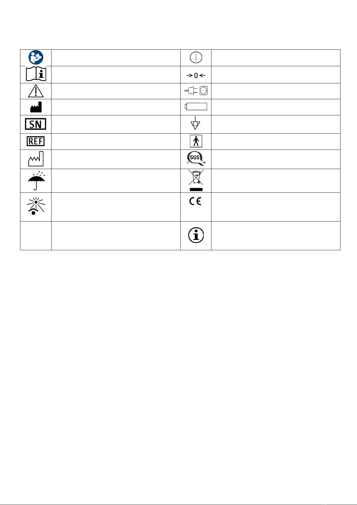
Symbols used
Refer to instructions for use
ON/OFF (press resp.)
Consult instructions for use Zero adjustment
Caution Power supply control lamp
Manufacturer Battery status indicator
Serial number
Equipotentiality
Catalogue number
Type BF applied part
Date of manufacture
NRTL approval mark for USA (US
testing company SGS)
Keep dry
Separate collection for WEEE (Waste
electrical and electronic equipment)
Keep away from sunlight
0297
Product complies with the
requirements of European Directive
93/42/EEC
Rx Only
Caution: Federal (USA) law restricts
this device to sale by or on the order of
a physician. Information note
General information
The instructions for use must be read carefully before use. The product may only be used according to
the described intended use. The manufacturer shall not assume liability or warranty for damage due to
inappropriate use or noncompliance with the instructions for use.
The product is to be transported and stored dry. The product is to be protected from sunlight. The
following conditions are to be maintained in order not to affect the product properties:
Transport conditions: -10 – 65°C, 10 – 90 % rel. hum.
Storage conditions: -10 – 35°C, 10 – 90 % rel. hum.
Ambient conditions in use: 10 – 35°C, 10 – 90 % rel. hum., 80 – 110 kPa
Warranty provisions
The warranty provisions laid down in Section 8 of the currently valid Terms and Conditions apply.

4
Technical data
The values given reflect nominal values and may, if applicable, deviate.
REF / Order number
HDM29.2
Software version
HDM 601D dated 04/10/2018
Measurement range
0 to +100 mmHg
Accuracy
+/- 2 mmHg
Operating voltage
115 to 230 V, ~ 50/60 Hz
Max. power consumption
40 VA
Weight
Approx. 1.5 kg
Monitor output
5 µV/mmHg/V
RS 232 C interface
9600 Bd, 8N1
Displays
Mean ICP [mmHg]
Systolic ICP [mmHg]
Diastolic ICP [mmHg]
Battery status indicator
Power supply indicator
Rechargeable battery
NiMH; 8.4 V; 1.6 Ah
Rechargeable battery life
24 months
Operating time battery
mode
Up to 6 hours
Charging time
2 – 8 hours
Classification
Class IIa (93/42/EEC)
Class I (IEC 60601-1)
Type BF applied part, permanent
operation
Not AP, not APG
IPX0
Maintenance of
rechargeable battery
Replace after 24 months
In accordance with
standards
IEC 60601-1
IEC 60601-1-2
Original package contents
ICP monitor HDM29.2
Mains cable
Monitor cable (optional)
Tested accessories
Spiegelberg probes and catheters
ICP probes
SND13.x.xx
IAP catheters
SND32.x.xx

5
Spare parts
Monitor cables
B.Braun/Lohmeier
KBL13.027.01
Criticare
KBL13.037.01
Datex-Cardiocap
KBL13.007.00/FV608
Datascope
KBL13.026.01
Digicare
KBL13.039.01
Dixtal
KBL13.042.01
Hellige 4th/5th generation
KBL13.003.00/FV609
Hewlett-Packard/Philips
KBL13.004.00/FV610
Marquette
KBL13.005.00/FV612
Mindray
KBL13.038.01
Nihon-Kohden 5-pin
KBL13.029.01
Propaque/Mennen
KBL13.009.00/FV617
Siemens/Dräger, 10-pin
KBL13.002.00/FV620
Siemens/Dräger, 16-pin
KBL13.024.01
Siemens/Dräger, 7-pin
KBL13.028.01
Space-Labs
KBL13.006.00/FV622
Nihon-Koden
KBL13.008.01/FV615
Computer cables RS 232, 9-pin
150 cm
KBL13.033.00/FV656
25 cm
KBL13.033.01
User group and environment
The ICP monitor should only be used by persons with a completed medical qualification as well as
having experience with neurological traumas (intensive care nurse).
The ICP monitor is intended exclusively for use in professional healthcare facility enviroment.
As the ICP-Monitor contains conductive components, it may not be used within or near an
electromagnetic field (e.g. MRT). Further information is provided in the accompanying brochure
Medical Electrical Devices according to IEC 60601-1-2.
Indication and intended use
The ICP monitor and the corresponding ICP probes are designed for the monitoring of intracranial
pressure (ICP) in the ventricle, in the parenchyma, subdurally, and epidurally. ICP monitoring is
indicated for craniocerebral trauma, diffuse and general hypoxia, subarachnoid haemorrhage,
pseudotumor cerebri, normal pressure hydrocephalus, postoperative swelling of the brain.
In addition, the ICP monitor can be used in combination with the Spiegelberg IAP catheter to monitor
intraabdominal pressure (IAP).
The air-pouch system consists of a plastic hollow body connected to a pressure transducer by tubing.
The pressure transducer, the electronic hardware, and the device for filling the air pouch are integrated
in the Spiegelberg ICP monitor. For epidural or subdural pressure measurement, the air pouch is placed
on or below the dura of the patient for intracerebral measurement in the ventricle or in the parenchyma.
The intracranial pressure is transmitted across the thin pouch wall to the air volume in the pouch and
transformed into an electric signal by the pressure transducer.

6
The digital display then shows the mean as well as the systolic and diastolic intracranial pressure (ICP).
The ICP monitor output provides both the mean pressure as well as the pulsatile signal.
After 10 minutes and once hourly thereafter, the ICP monitor opens the pressure transducer to
atmospheric pressure for zero adjustment.
Contraindication
The ICP monitor may not be used for purposes other than those indicated. The contraindications to
ICP monitoring result from the contraindications of the ICP probes to be used, which include the
following points, among others: infections of the scalp, in patients receiving anticoagulant therapy,
bleeding tendency and when continuous monitoring by trained personnel cannot be guaranteed.
Safety notes and warnings
Handling of the ICP monitor is to be performed with care and caution.
The ICP monitor may only be used with approved accessories.
The ICP monitor may only be serviced and repaired by qualified personnel.
Before each use, check the ICP monitor for external damage that could affect the components
(e.g. heavily deformed housing).
A reliable contact with the protective earth is only guaranteed if the supplied power cable is used.
After heavy mechanical stress on the ICP monitor (e.g. due to dropping), the ICP monitor must
be sent to the manufacturer for inspection.
To avoid the risk of electric shock, the ICP monitor must only be connected to a power supply
system with a protective earth.
If fluid enters the ICP monitor unintentionally, the mains cable must be disconnected
immediately.
In order to prevent moisture due to condensation, the ICP monitor must be stored at room
temperature prior to use for some time.
The ICP monitor is not suitable for use in areas where there is a danger of explosions or in an
MR room or a magnetic field.
The ICP monitor is not intended for use in electrosurgery/diathermy.
After prolonged non-use of the ICP monitor, the entire battery capacity is no longer available.
The rechargeable battery should be replaced at least every two years.
7
It must be ensured that the classification of all devices connected to the ICP monitor is suitable
to the application with regard to protection from electric shock.
Avoid using the ICP monitor directly next to or with other stacked devices, as this could result in
an incorrect operation mode. If use in the prescribed manner is nonetheless necessary, the ICP
monitor and the other devices should be observed to ensure that they are working properly.
All configurations must comply with the IEC 60601-1-1 system standard. The person connecting
the devices is responsible for the configuration and must ensure that the system standard
IEC 60601-1-1 or corresponding national standards are complied with.
The use of accessories, transducers and leads other than those specified or provided by the
manufacturer of the ICP monitor may result in increased electromagnetic interference emissions
or reduced electromagnetic immunity of the device and result in faulty operation.
Portable HF communication devices (radio equipment) (including their accessories such as
antenna cables and external antennas) should not be used at a distance of less than 30 cm (or
12 inches) from the parts and cables of the ICP monitor designated by the manufacturer. Non-
observance can lead to a reduction in the performance characteristics of the ICP monitor.
Routinely check electrical plugs and cables. Do not use if they are damaged.
Do not immerse the cables in liquids and do not bring the electrical connection into contact with
liquids.
Do not sterilize the cable in an autoclave.
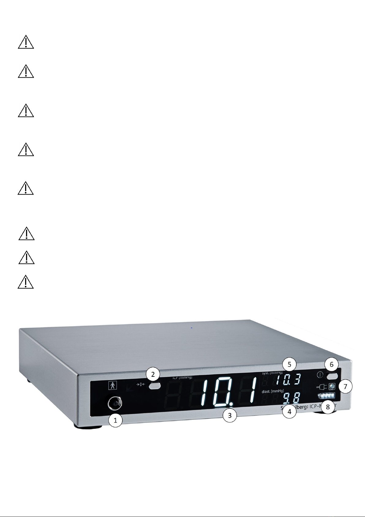
HDM29.2 - Front panel

8
HDM29.2 - Rear panel

9
Application and handling
In the following, the application parts are referred to as "probes". This term includes both the ICP probes
and the IAP catheter. The individual steps apply equally to both product groups.
Setting up the ICP monitor
The ICP monitor must be placed on a level surface in order to be used for its intended purpose. The
display panel must be freely accessible to the user.
The distance to the patient must be selected so that the connected probe is not tensioned or pulled
out.
1. Connect the ICP monitor to a power source using the supplied mains cable.
2. Check whether the ICP monitor is correctly connected to the mains (mains control lamp (7) lights
up).
3. If necessary, connect the equipotential bonding connector (10) with an equipotential bonding box.
NOTE! If the ICP monitor is used in battery mode, make sure that the rechargeable battery
is fully charged before use.
Connecting the probe
WARNING! Before connecting the probe, neither the connector on the probe nor the
probe connection (1) must be disinfected, as fluid could otherwise enter the probe
connection (1). This could lead to damage of the ICP monitor.
NOTE! The ICP monitor must be switched off before connecting the probe.
1. Insert the probe into the patient according to the manufacturer's instructions.
2. Connect the probe connector to the probe connection (1) of the ICP monitor.
3. Turn the connector clockwise until the probe is firmly connected to the ICP monitor.
NOTE! The probe must be firmly connected to the ICP monitor to prevent leakage and the
resulting deviations in measurement values.
Switch on the ICP monitor
NOTE! A segment test is performed after switching on the ICP monitor. All segments of
the display (3, 4, 5, 8) including the red arrow at the probe connection (1) light up. Only
then, is appropriate use possible.
1. Press the On/Off button (6) to switch on the ICP monitor.
2. Check whether all segments in the display (3-8) light up during the segment test.
3. Wait until the filling process of the probe is completed and the median ICP is shown in the display
(3). This can take up to 30 s.
WARNING! Do not press the On/Off button (6) and the "Zero" button (2) simultaneously.
This leads to problems during initialisation, which causes incorrect initial values to be
displayed.
NOTE! No manual zeroing or calibration is required after switching on the ICP monitor.

10
NOTE! If there is a fault at the probe connection (1) or the pneumatic unit, a red arrow on
the probe connection (1) lights up.
WARNING! When operating on mains power, check that the mains control lamp (7) is on.
Otherwise, the ICP monitor runs in battery mode and discharges.
Reading the ICP values
The median ICP in mmHg (3) is shown in large digits on the display of the ICP monitor. The systolic
(5) and diastolic (4) ICP can be read in mmHg to the right.
NOTE! The display values of the systolic (5) and diastolic ICP (4) must be used to confirm
the median ICP (3).
NOTE! If the amplitude between the systolic (5) and diastolic ICP (4) is very low or non-
existent, this indicates an error. In this case, check the probe for kinks, constriction,
pinching or a faulty connection to the ICP monitor and check whether the ICP monitor is
switched on.
NOTE! An unstable signal path indicates a leakage in the pneumatic system. In this case,
shut down the ICP monitor and contact the manufacturer.
Connecting to a patient monitor
NOTE! Only cables authorized by Spiegelberg may be used for connecting the ICP
monitor.
1. Connect the monitor cable to the rear connector "Monitor" (11) and the ABP input of the patient
monitor.
2. Switch on the patient monitor and the ICP monitor (if not already done).
3. Press the "Zero" button (2) on the ICP monitor. The message "0.0" flashes on the display (3).
4. Zeroing of the patient monitor within 10 s according to the manufacturer's specifications.
5. Compare the median ICP on the ICP monitor (3) with the display on the patient monitor.
NOTE! The ICP monitor must always be switched on when in use with a patient monitor.
If the patient monitor is connected to an ICP monitor which is switched off, the patient
monitor may display a pressure signal without amplitude. This does not reflect the actual
measured value.
NOTE! During initialisation of the ICP monitor (zeroing the probe), a display of up to 100
mmHg may appear on the patient monitor. This does not reflect the actual measured
value.
NOTE! The screw connections of the monitor cables must be tightened firmly to prevent
disconnection when moving the ICP monitor.
Connecting to a computer
NOTE! Only cables authorized by Spiegelberg may be used for connecting the ICP
monitor.
Connect the computer cable to the "RS 232" (12) connector on the back of the ICP monitor and the RS
232 connector of the computer.
NOTE! The screw connections of the computer cables must be tightened firmly to prevent
disconnection when moving the ICP monitor.

11
Operation with battery mode
WARNING! Before using the battery mode, check the battery charge level using the
battery status indicator (8). If the battery is not sufficiently charged, the ICP monitor may
switch off.
WARNING! Charge the ICP monitor when a red LED appears in the battery status indicator
(8) and flashes.
Disconnect the ICP monitor from the power by unplugging the mains cable. The battery status indicator
(8) shows the battery charge status. If the battery is low, an LED on the battery status indicator (8)
lights up red. If discharge continues, this starts flashing.
Resumption of measurement after interruption
This step describes the continuation of the ICP measurement after an interruption, which can, for
example, occur due to the transport of the patient or the changing of a probe.
NOTE! After disconnecting the probe from the ICP monitor as well as before reconnecting
the probe, the ICP monitor should always be switched off.
1. Check that the ICP monitor is switched off.
2. Connect the probe connector to the probe connection (1) of the ICP monitor.
3. Turn the connector clockwise until the probe is firmly connected to the ICP monitor.
4. Press the On/Off button (6) to switch on the ICP monitor.
5. Check whether all segments in the display (3, 4, 5, 8) light up during the segment test.
NOTE! If the ICP monitor is switched on while the probe is connected, it must be restarted
by pressing the On/Off button (6) twice.
Ending the measurement
1. Switch off the ICP monitor by pressing the On/Off button (6).
2. Disconnect the probe from the ICP monitor by turning the connector counterclockwise.
Cleaning
WARNING! During cleaning, make sure that no moisture enters through the open
connections on the front and rear (1, 9-12). If necessary, these must be covered before
cleaning.
1. Disconnect the ICP monitor from the power supply by unplugging the mains cable from the ICP
monitor (9).
2. Wipe the surfaces of the ICP monitor with a damp cloth.
3. Monitor cable: clean the insulating parts of the cable with lukewarm soapy water with a damp cloth
as often as necessary.
Maintenance
WARNING! Maintenance work may only be carried out by competent persons and only in
accordance with the manufacturer's instructions.
The ICP monitor should be serviced annually by competent persons in order to maintain its functionality
and to detect possible failures at an early stage. Maintenance must be carried out in accordance with
the instructions specified by Spiegelberg. These are available from Spiegelberg upon request.
Alternatively, the ICP monitor can be sent to Spiegelberg for maintenance purposes. Spiegelberg
reserves the right to charge the maintenance costs to the customer.

12
Disposal
The ICP monitor must be disposed of by separate waste disposal for electrical and electronic
equipment. If necessary, contact your dealer or the manufacturer.
Faults and errors
If problems occur with the ICP monitor, error messages are shown in the display (3). The following
table briefly explains the error messages, their causes and possible solutions for correction. If the fault
persists, the ICP monitor must be taken out of operation and sent to the manufacturer.
Fault message
Possible cause
Action
The ICP monitor will
not start
The mains plug is not plugged in
and the battery is discharged
Connect the ICP monitor to the mains
and charge the battery
The arrow on the
probe connection (1)
flashes and an
acoustic signal sounds
Probe or connection leaks
Check whether the probe is correctly
connected to the ICP monitor and if the
probe is leaking.
"E01", arrow on probe
connection (1) flashes,
acoustic signal sounds
Probe or probe connection (1) is
blocked
Check the probe for kinks, constrictions,
pinches or incomplete unfolding
„E04“
Problem in the pneumatic unit
(internal error)
The ICP monitor may no longer be used
and must be sent to the manufacturer
„E06“
„E09“
Incorrect CRC checksum in
EEPROM
„E10“
Blocked motor in the pneumatic
unit
"E11“
Incorrect scaling factor in
EEPROM
„E12“
Incorrect mechanical zero offset

Manufacturer:
Spiegelberg GmbH & Co. KG
Tempowerkring 4
21079 Hamburg
Germany
Tel.: +49-40-790-178-0
Fax: +49-40-790-178-10
E-mail: info@spiegelberg.de
http://www.spiegelberg.de
Subject to technical modifications without notice.
Version: 10 / 2023-03-28
0297
© by Spiegelberg GmbH & Co. KG 2018
Table of contents
Other Spiegelberg Monitor manuals


