spinflo Country Leisure HB10000 NG Operating instructions

GAS APPLIANCES
C
O
U
N
T
R
Y
L E I S U R E
BUILD IN COOKING HOB
FOR USE WITH NATURAL GAS
USER AND INSTALLATIO
N INSTRUCTIONS
MODEL HB10000 NG
4 Burner Hob
CAUTION – ALL OUTER SURFACES WILL GET HOT
WHEN IN USE
SPINFLO LIMITED
19 OAKHAM DRIVE
PARKWOOD IND. EST.
SHEFFIELD S3 9QX, ENGLAND
TEL: + 44 (0)114 273 8157 FAX: + 44 (0)114 275 3094
PCC1269NG – Issue 0

MODEL HB10000NG - USER INSTRUCTIONS
INTRODUCTION
In your own interest of safety, it is law that all gas appliances be installed by
competent persons. CORGI (Confederation for the Registration of Gas
Installers) registered installers undertake to work to safe and satisfactory
standards. Failure to install the appliance correctly could invalidate any warranty
or liability claims and lead to prosecution. This appliance shall be installed in
accordance with the local and national/European standards in force. Particular
attention shall be given to the requirements regarding ventilation. Read the
instructions before installing or using this appliance.
PROVISION OF VENTILATION
The use of a gas cooking appliance results in a production of heat and moisture
in a room in which it is installed. Ensure that the kitchen is well ventilated: keep
natural ventilation holes open or install a mechanical ventilation device,
(mechanical extractor hood).
Prolonged intensive use of the appliance may call for additional ventilation, for
example opening a window, or more effective ventilation, for example
increasing the level of mechanical ventilation where present.
The room containing the cooker should have an air supply in accordance with
local and national/European standards.
IMPORTANT
This appliance is suitable for use with NATURAL GAS and should not be used
on any other gas. The following gas pressures should be used: -
CAT I
2
H(20)
NATURAL GAS (G20) 20 mbar
POSITION
This appliance must be positioned free from draughts, which may affect the
combustion, and in a manner that will prevent the accumulation of unburnt gas.
When in use ensure that air vents are not inadvertently blocked or shut off.
OPERATION
Ensure the gas cylinder or mains supply is turned on.
In the event of a gas smell turn off at the cylinder and contact supplier.
Burners - Each burner is controlled individually and is monitored by a flame
supervision device. In the event of the burner flames being accidentally
extinguished, turn off the burner control and do not attempt to re-ignite the
burner for at least one minute. The respective knob positions are as shown in
fig 1:-
GB

Fig 1.
To light the burner, press in and turn the knob anti-clockwise to the full rate
position and apply a light to the burner or press the ignition button if fitted. It is
necessary to hold the knob depressed during ignition and for approximately
fifteen seconds after the burner has lit to allow the probe to reach temperature.
Should the flame go out when the knob is released, the procedure should be
repeated holding the knob depressed for slightly longer.
For simmering, turn the knob further anti-clockwise to the low rate position. To
turn the burner off, rotate knob fully clockwise until the line on the knob lines up
with the dot on the control panel. The burners on this appliance have fixed
aeration and no adjustment is required. The burners should flame as follows:-
Natural Gas - The flames should burn quietly with a blue/green colour
with no sign of yellow tips.
Each of the burners will accommodate pans from 10 to 22cm, although care
should be taken not to overload the appliance as reduced performance may
result.
When using small pans, the flame should not spread beyond the base of the
pan as this will reduce the efficiency of the burner.
DO'S AND DON'TS
DO read the user instructions carefully before using the appliance for
the first time.
DO allow the burners to heat before using for the first time, in order to
expel any smells before the introduction of food.
DO clean the appliance regularly.
DO remove spills as soon as they occur.
DO check that controls are in the off position when finished.
DO NOT allow children near the appliance when in use. Turn pan handles
away from the front so that they cannot be caught accidentally.
DO NOT allow fats or oils to build up in the base of the hotplate.
DO NOT use abrasive cleaners or powders that will scratch the surfaces of
the hotplate.
DO NOT under any circumstances use the appliance as a space heater.

LEAKS
If a smell of gas becomes apparent, the supply should be turned off at the
cylinder or mains supply IMMEDIATELY.
Extinguish naked lights including cigarettes and pipes. Do not operate electrical
switches. Open all doors and windows to disperse any gas escape. The strong
unpleasant smell of gas will enable the general area of the leak to be detected.
Check that the gas is not escaping from an unlit appliance. Never check for
leaks with a naked flame; leak investigation should be carried out using a leak
detector spray .
MAINTENANCE & SERVICING
This appliance needs little maintenance other than cleaning. All parts should be
cleaned using warm soapy water. Do not use abrasive cleaners, steel wool or
cleansing powders. When cleaning the burner ring it is essential to ensure that
the holes do not become blocked. The control knobs are a push fit and can be
removed for cleaning. They are interchangeable without affecting the sense of
operation.
On units fitted with battery spark ignition, when the time taken for spark
generation becomes extended, the battery should be renewed with a suitable
make of long life battery.
ALL SERVICING MUST BE CARRIED OUT BY AN APPROVED
COMPETENT PERSON. AFTER EACH SERVICE THE APPLIANCE MUST
BE CHECKED FOR GAS SOUNDNESS.
INSTALLATION INSTRUCTIONS
SPECIFICATION
This appliance is for use on NATURAL GAS.
CAT I
2
H(20)
NATURAL GAS (G20) 20 mbar
External dimensions (WxD) 580 x 500
Heat input – Hotplate burners 1 x 1.0kW; 3 x 1.6kW
Injector size:-Hotplate burners 1.0kW = 0.50mm
1.6kW = 0.62mm
Spark ignition (where fitted) is 12V or 240V.

INSTALLATION
The gas supply input pressure to which this appliance is connected, MUST not
rise or fall by more than 2.5 mbar from nominal when ALL appliances
connected to the supply are OPERATED simultaneously.
If this appliance is not installed in accordance with the instructions and
tolerances detailed herein, we the manufacturer can not be held responsible for
any problems that occur, or poor performance that is perceived/witnessed.
In your own interest of safety, it is law that all gas appliances be installed by
competent persons. CORGI (Confederation for the Registration of Gas
Installers) registered installers undertake to work to safe and satisfactory
standards. Failure to install the appliance correctly could invalidate any warranty
or liability claims and lead to prosecution. This appliance shall be installed in
accordance with the local and national/European standards in force. Particular
attention shall be given to the requirements regarding ventilation. Read the
instructions before installing or using this appliance.
LOCATION OF APPLIANCE
This appliance maybe installed in a kitchen/kitchen diner but NOT in a room
containing a bath or a shower.
VENTILATION
This appliance must be installed according to the relevant local and
national/European standards in force.
This appliance is suitable for installation into Holiday Homes, Touring Caravans
and Boats. In all cases the national standards with regard to ventilation for the
particular vehicle into which the appliance is to be installed must be adhered to.
CONNECTION
An 8mm gas inlet point is provided on the underside of the appliance. It is
recommended that the unit be connected by copper tubing using an appropriate
connector.
Rubber tubing must NOT be used.
If the unit is fitted with spark ignition, care must be taken when the hob is sited
in position that none of the wires come into contact with the underside of the
hob or burner cups, as this could cause failure of the spark ignition to the hob.
After installation the appliance must be tested for soundness.
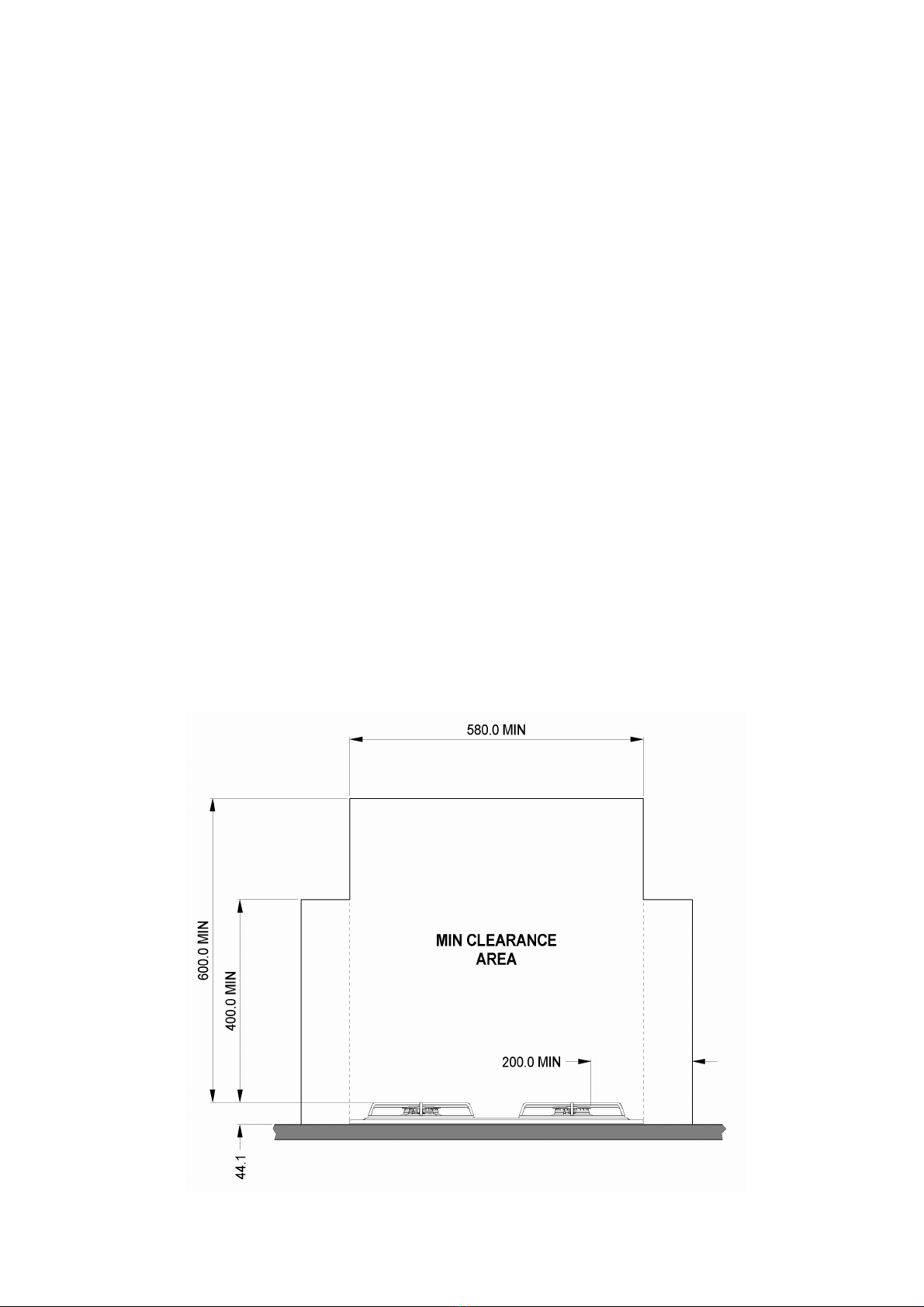
POSITION
This appliance must be installed in such a way that the furniture fitted around
the unit is manufactured from suitable material and follows the minimum
dimensions as shown in Fig 2. If this cannot be adhered to because of design
constraints, then the design is deemed permissible providing that the
temperature rise on the furniture is tested. To establish whether the temperature
rise is acceptable, the following test must be verified:
Place 4 large pans on top of the hotplate burners and fill up ¾with
water. Turn on all hotplate burners to full. After 60 minutes establish
the highest temperature points on all the furniture surfaces in direct
line of sight of the appliance. The temperature rise must not exceed
65ºC above the ambient temperature, or where applicable, must not
exceed the maximum allowable temperature, to avoid damage, as
detailed within the suppliers material specification.
A horizontal difference of 200mm must exist between the edge of the burner
and combustible material unless protected by a layer of non-combustible
material.
All combustible materials such as curtains and shelves must be kept
well clear of the appliance.
This appliance must be positioned free from draughts, which may affect the
combustion, and in a manner that will prevent the accumulation of unburnt gas.
When in use ensure that air vents are not inadvertently blocked or shut off.
The underside of the appliance must be shielded. It is recommended that the
shield is fabricated from non-combustible material, but if the enclosure is
manufactured from combustible material, then a minimum air space of 100mm
must exist between the material and the lowest part of the appliance. THIS AIR
SPACE MUST BE WELL VENTILATED.
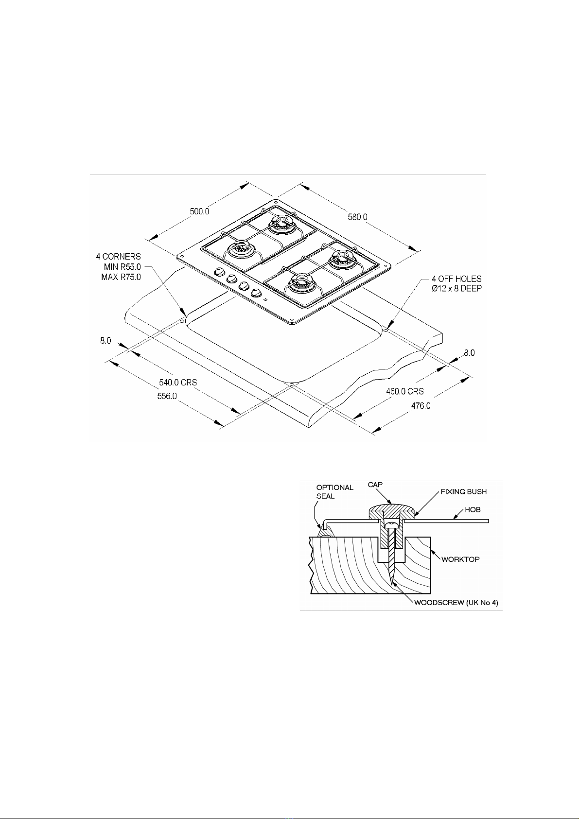
WORKTOP PREPARATION
A cut out should be prepared in the worktop as shown below. The unit should
not be fitted in a position exposed to strong draughts, since this always reduces
the efficiency of the burners.
FIXING DETAILS
SCREW FIXING DETAILS WITH HOB
FIXED IN PLACE USING THE FIXING
BUSHES PROVIDED
Table of contents
Other spinflo Hob manuals

spinflo
spinflo H200F Operating instructions

spinflo
spinflo 160 Series Operating instructions

spinflo
spinflo 656/MK 12 Operating instructions

spinflo
spinflo H200F Operating instructions

spinflo
spinflo H400F Operating instructions

spinflo
spinflo Country Leisure HB10000 Operating instructions

spinflo
spinflo Country Leisure HB9000EL Operating instructions

spinflo
spinflo HB15000 Operating instructions

spinflo
spinflo S-656/MK 12 series Operating instructions


