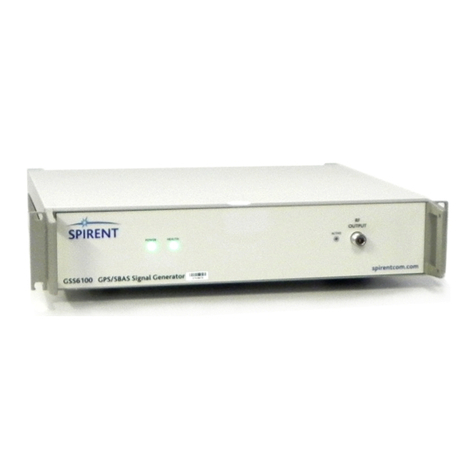
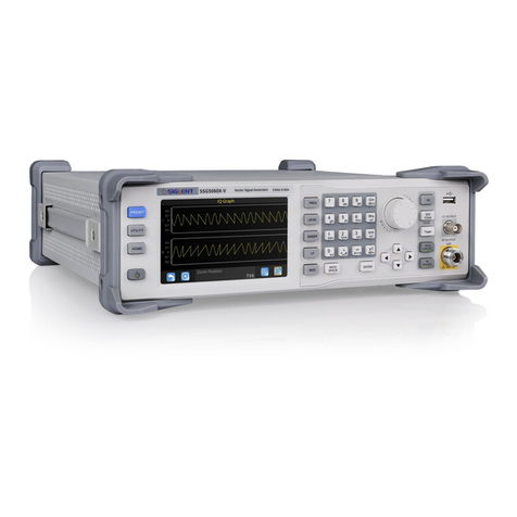
Spirent GSS7725 User manual

DGP01448AAA Issue 6-00August 2017
Document status: APPROVED
GSS7725 INTERFERENCE GENERATOR USER MANUAL

PROPRIETARY INFORMATION
THE INFORMATION CONTAINED IN THIS DOCUMENT IS THE PROPERTY OF SPIRENT COMMUNICATIONS
PLC. EXCEPT AS SPECIFICALLY AUTHORISED IN WRITING BY SPIRENT COMMUNICATIONS PLC, THE
HOLDER OF THIS DOCUMENT SHALL KEEP ALL INFORMATION CONTAINED HEREIN CONFIDENTIAL AND
SHALL PROTECT SAME IN WHOLE OR IN PART FROM DISCLOSURE AND DISSEMINATION TO ALL THIRD
PARTIES TO THE SAME DEGREE IT PROTECTS ITS OWN CONFIDENTIAL INFORMATION.
©COPYRIGHT SPIRENT COMMUNICATIONS PLC 2016-2017

6-00 DGP01448AAA
GSS7725 Interference Generator User Manual
© Spirent Communications plc 2002-2017
1-1
General
Contents
CHAPTER 1: GENERAL 1-3
1.1 This issue 1-3
1.2 Referenced documents 1-3
1.3 Copyright notices 1-3
1.4 Document format 1-4
1.5 Safety 1-4
CHAPTER 2: OVERVIEW 2-1
2.1 Technical Performance 2-1
2.2 Connectivity 2-1
2.3 Environmental & Safety 2-2
2.4 Operating parameters 2-2
2.5 Test Waveforms 2-3
CHAPTER 3: INTRODUCTION 3-1
3.1 Phases of operation 3-1
3.2 Nomenclature 3-1
CHAPTER 4: HARDWARE CONFIGURATION 4-1
4.1 External reference 4-1
4.2 Connectivity 4-1
4.3 GSS6300Mi 4-1
4.4 GSS6700 4-2
4.5 GSS7000 4-2
4.6 GSS9000 4-3
4.7 Power on sequence 4-3
4.8 Firewall Rules 4-3
CHAPTER 5: SCENARIO DEFINITION 5-1
5.1 Signal types 5-1
5.2 Use File 5-2
Interference Simulation File editor 5-3
Using the Interference Simulation File editor 5-4
5.3 Interactive mode 5-4
5.4 Interference commands 5-5
Comment 5-5
Interference Custom Waveform 7725 5-5
Interferer RF on/off 5-7
Interferer Level 5-8
Interferer Delta level 5-9
Operating mode with a User actions file and an interference file 5-9
5.5 Remote control interference commands 5-10
CHAPTER 6: INDEPENDENT REMOTE CONTROL 6-1
6.1 Configuration file 6-1
6.2 GSS7725 controller 6-1
6.3 Connecting to the controller 6-1
6.4 Remote command syntax 6-2
6.5 Remote commands 6-2
CHAPTER 7: CALIBRATION 7-1
7.1 Equipment required 7-1
7.2 Testing the output level 7-1
7.3 Calibrating the output level 7-2
TERMS & ABBREVIATIONS A-1
A.1 Simulator terms A-1

DGP01448AAA 6-00
1-2
General
GSS7725 Interference Generator User Manual
© Spirent Communications plc 2002-2017
A.2 Abbreviations and acronyms A-2
SPIRENT CUSTOMER SUPPORT B-1
INDEX AND LIST OF FIGURES AND TABLES C-1
INDEX C-1
LIST OF FIGURES C-3
LIST OF TABLES C-4

6-00 DGP01448AAA
GSS7725 Interference Generator User Manual
© Spirent Communications plc 2002-2017
1-3
General
Chapter 1: General
1.1 This issue
Note: “PosApp release” refers to the PosApp release for which this user manual is valid.
Earlier releases of PosApp may have reduced functionality compared with this release.
Spirent recommends you always use the latest PosApp release.
Issue Date PosApp
release
Description
1-00
Nov
2016
5.07 SR02
Bugz:13332, Support for GSS7725
2-00
Feb
2017
6.00 SR04
Separate controller for GSS7725 V2.0 controller software
3-00
March
2017
6.00 SR04
Reference to sig_gen.txt, lservrc.txt and Cal_9
4-00
April
2017
6.01
Formatting and clarification
5-00
June
2017
6.01
Calibration procedure change
1.2 Referenced documents
a) DGP00686AAA SimGEN Software User Manual.
b) MS7725 GSS7725 Interference Generator Datasheet with Product Specification.
c) DGP00792AAA SimREMOTE User Manual.
1.3 Copyright notices
This document may use the following trademarks or registered trademarks:
Microsoft and Windows - trademarks or registered trademarks of Microsoft Corporation.
InstallShield - a registered trademark of InstallShield Software Corporation.
Alpha - a registered trademark of Hewlett Packard.
NovAtel - a registered trademark of NovAtel Inc.
MATLAB - a registered trademark of The Mathworks Inc.
All other company/product names are trademarks and/or service marks; or registered trademarks
and/or service marks of the respective holders.
WinPcap copyright notice:
Copyright (c) 1999 - 2005 NetGroup, Politecnico di Torino (Italy).
Copyright (c) 2005 - 2007 CACE Technologies, Davis (California).
All rights reserved.
Redistribution and use in source and binary forms, with or without modification, are permitted
provided that the following conditions are met:
1. Redistributions of source code must retain the above copyright notice, this list of conditions and
the following disclaimer.
2. Redistributions in binary form must reproduce the above copyright notice, this list of conditions
and the following disclaimer in the documentation and/or other materials provided with the
distribution.

DGP01448AAA 6-00
1-4
General
GSS7725 Interference Generator User Manual
© Spirent Communications plc 2002-2017
3. Neither the name of the Politecnico di Torino, CACE Technologies nor the names of its
contributors may be used to endorse or promote products derived from this software without
specific prior written permission.
THIS SOFTWARE IS PROVIDED BY THE COPYRIGHT HOLDERS AND CONTRIBUTORS "AS
IS" AND ANY EXPRESS OR IMPLIED WARRANTIES, INCLUDING, BUT NOT LIMITED TO, THE
IMPLIED WARRANTIES OF MERCHANTABILITY AND FITNESS FOR A PARTICULAR
PURPOSE ARE DISCLAIMED. IN NO EVENT SHALL THE COPYRIGHT OWNER OR
CONTRIBUTORS BE LIABLE FOR ANY DIRECT, INDIRECT, INCIDENTAL,
SPECIAL, EXEMPLARY, OR CONSEQUENTIAL DAMAGES (INCLUDING, BUT NOT LIMITED
TO, PROCUREMENT OF SUBSTITUTE GOODS OR SERVICES; LOSS OF USE, DATA, OR
PROFITS; OR BUSINESS INTERRUPTION) HOWEVER CAUSED AND ON ANY THEORY OF
LIABILITY, WHETHER IN CONTRACT, STRICT LIABILITY, OR TORT (INCLUDING
NEGLIGENCE OR OTHERWISE) ARISING IN ANY WAY OUT OF THE USE OF THIS
SOFTWARE, EVEN IF ADVISED OF THE POSSIBILITY OF SUCH DAMAGE.
1.4 Document format
Table 1-1 shows the formats used in this document.
Table 1-1 Formats used in this document
Format Description
Clear
Button name (with extra description to avoid ambiguity)
Edit
Menu item (with extra description to avoid ambiguity)
SimGEN.exe
Filename
Note: Insert the dongle
Important information
“Text”
Text entered from keyboard
Signal control - General
Title of dialog or window (with extra description to avoid ambiguity)
Signal Definition
Title of area within a dialog or window
code
Used for lines of code
code inverted
Used to enhance certain characters in lines of code
1.5 Safety
SAFETY WARNING
You must connect this signal generator to
mains earth (ground)
Completely isolate mains power by removing the plug from the mains
socket, which should be close to the signal generator and readily
accessible
NOTICE
Wait 10 seconds before re
-applying mains power to avoid blowing the mains
fuses

6-00 DGP01448AAA
GSS7725 Interference Generator User Manual
© Spirent Communications plc 2002-2017
2-1
Overview
Chapter 2: Overview
This document describes the GSS7725 Interference Simulation System. It details the configuration
and operation of the GSS7725 using SimGEN and standalone use.
It is an addendum to reference a), the SimGEN User Manual.
2.1 Technical Performance
Table 2-1 GSS7725 Technical Performance
Parameter
GSS7725
Frequency Range
850MHz to 2.2 GHz
Frequency Resolution
100 Hz
Frequency Stability
<± 1 ppm/yr, ± 1 ppm typical over 0 to +55°C
Bandwidth (3dB)
Up to 25 MHz
In band flatness
± 1.5 dB RSS
In band spurious
<-25 dBc
Harmonics
<-25 dBc
GNSS signal level
-130 dBm
GNSS signal level control
± 20 dB
GNSS signal level accuracy
± 1.0 dB RSS
I/S ratio relative to nominal GPS C/A signal
level
0 to +110 dB
Interference level expressed as absolute
power
1
-130 to -20 dBm
Interference accuracy (CW) – I/S 10 to 110
dB
± 2.0 dB RSS
Interference level resolution
1 dB (nominal)
Note:
1) Specified maximum interferer level in ambient +20 to +30 °C. Typically the maximum level reduces by
0.2 dB/°C outside of this range.
2.2 Connectivity
Table 2-2 GSS7725 Connectivity
Port
Type
Detail
Description
RF OUTPUT
OUT
Coaxial Type ‘N’
Female
Front Panel
Provides the primary Combined GNSS
+ Interference signal output at specified
levels.
50 ohm VSWR <1.25:1 (in band).
DC isolated
1
GNSS IN
IN
SMA
Provides connectivity to GNSS input
source.
50 ohm VSWR <1.25:1 (in band).
DC isolated
1
10 MHz
IN
Coaxial Type ‘BNC’
Socket
Allows the GSS7725 to be locked to an
external reference of 10 MHz sine or

DGP01448AAA 6-00
2-2
Overview
GSS7725 Interference Generator User Manual
© Spirent Communications plc 2002-2017
Port
Type
Detail
Description
Rear Panel
square wave. Recommended
operation
1PPS
IN
Coaxial Type ‘BNC’
Socket
Rear Panel
TTL level compatible 50 ohm
ETH0
IN/OUT
RJ-45
This is used for control of the
GSS7725 hardware or can be used for
passing through to a LAN.
ETH1
IN/OUT
RJ-45
This is used for control of the
GSS7725 hardware or can be used for
passing through to a LAN.
12V IN
12V DC input from an external power
supply
Notes:
1) DC Isolation can withstand a maximum DC level of ±60V and reverse RF levels to a maximum of 1W.
2.3 Environmental & Safety
The GSS7725 is suitable for operation only in a typical office or laboratory environment.
Table 2-3 GSS7725 Environmental & Safety parameters
Property
Description
Temperature range
+15°C to +40°C
The equipment employs forced-air cooling
Relative Humidity
75% max
Mechanical
Not exposed to vibration, shock or bump
Storage conditions
-40°C to +70°C
Power requirements
100 to 120 VAC, 50 to 60 Hz
220 to 240 VAC, 50 to 60 Hz
30W maximum
EMC
EMC Directive 2014/30/EU
EN 61326-1:2013 Electrical equipment for measurement, control
and laboratory use.
Safety
Low Voltage Directive (LVD) 2014/35/EU
IEC 60950-1:2005 (ED2) + A1:2009 + A2:2013 Information
technology equipment.
2.4 Operating parameters
Table 2-4 GSS7725 Operating parameters
Property
Description
OS for controller software
Windows 7 64 bit
IQ Input file sample rates
4, 16, 26, 51.5 & 120 MS/s
(default 16 MS/s)
IQ input file format
Binary, 16 bit (2 byte) per sample, interleaved I&Q (I0Q0I1Q1I2Q2…)
Big or little endian supported (default big endian)
Frequency
Can only be updated in non-transmit state.

6-00 DGP01448AAA
GSS7725 Interference Generator User Manual
© Spirent Communications plc 2002-2017
2-3
Overview
Property
Description
(default 1.57542 GHz)
Reference clock
Can only be updated in non-transmit state.
(default internal)
Output sample rates
25 MS/s
Attenuator range
0 dB to 110 dB
Can be set/changed in transmit state with an update rate of 2 Hz
(default 0 dB)
Controller to PosApp IP
Address
192.168.5.30 (default PCIe card)
Controller to GSS7725 IP
addresses
192.168.10.1 (default motherboard)
2.5 Test Waveforms
Four test waves forms are contained within the install.
Table 2-5 GSS7725 Default Waveform Definitions
Waveform
Description
0x7FFF.bin
16 MS/s, big endian, CW signal, full power
0x4000.bin
16 MS/s, big endian, CW signal
test_full.bin
16 MS/s, big endian, swept frequency
tones_full_long.bin
16 MS/s, big endian, two tone test


6-00 DGP01448AAA
GSS7725 Interference Generator User Manual
© Spirent Communications plc 2002-2017
3-1
Chapter 3: Introduction
Spirent designed the GSS7725 to test Satellite Navigation receiver equipment in a simulated
environment. The GSS7725 supports the playing of pre-canned IQ files that have been generated
by either Spirent equipment or a third-party software. The interference is output at RF and
optionally combined with the GNSS input from a Spirent signal generator. The output RF power of
the GSS7725 can be controlled independently from the output RF power from a Spirent GNSS
signal generator.
3.1 Phases of operation
This manual describes the operation of the GSS7725 in four separate phases:
Hardware Configuration
Describes the hardware interconnection of the GSS7725 and the interconnection to the software.
Scenario Definition
Guides you through defining the simulated interference environment.
Scenario Run-Time & Remote Control through SimGEN
Guides you through how to control the GSS7725 at run time while running a previously specified
interference scenario.
Remote control
Guides you through how to take direct control of the GSS7725
3.2 Nomenclature
SimGEN and this document refer to various components using the Spirent nomenclature defined
below.
SimGEN simulates one or more Vehicles, each Vehicle may have one or more Antennas mounted
on it. Each Antenna corresponds to an RF port, either on the front or rear panel of the signal
generator, or on the front panel of the GSS7725.
When you connect one (or more) GPS receivers to the RF output ports, the receiver functions as
though it is connected to the simulated antenna mounted on the simulated vehicle.
The dual-output, GSS9000-series and GSS8000-series signal generators have two RF ports on the
front panel, and can simulate two Vehicles, each with one antenna; or one Vehicle with two
separate antennas. Alternatively, the single output signal generators may operate in L1/L2 mode,
where the RF port produces an RF signal feeding a single antenna mounted on a single vehicle.
You can combine up to four units to allow multiple vehicles/multiple antennas or multiple L1/L2
vehicle/antenna combinations.
The GSS7727 has a single RF input and a single combined RF output. A single GSS7725 may
only be associated with one scenario antenna. Between scenarios, you can switch the GSS7725
between scenario antennas.
The collective name for the interference environment you require that incorporates the satellite
constellation, vehicle motion, atmospheric effects and antenna properties is a Scenario.


6-00 DGP01448AAA
GSS7725 Interference Generator User Manual
© Spirent Communications plc 2002-2017
4-1
Chapter 4: Hardware configuration
Note:
1) This chapter describes the GSS7725 using single signal generator with one RF output
2) If the GSS7725 is being added to an existing Spirent GSS signal generator a new sig_gen.txt
file is required to describe the new configuration as well as a new licence file lservrc.txt
3) For use with GSS9000 a Cal_9 will also be supplied. This file describes the path loss and delay
through the GSS7725 and connecting cable.
4) For use with GSS7000 a Cal_7 will also be supplied. This file describes the path loss and delay
through the GSS7725 and connecting cable.
4.1 External reference
Spirent recommends you lock your GSS7725 to an external 10 MHz reference and optionally a 1
PPS source, both these signals are output from a Spirent GSS signal generator.
Connect the external 10 MHz reference to the 10MHz port found on the back of the GSS7725.
4.2 Connectivity
The following sections show the interconnect diagrams for simple configurations of the GSS7725
with the Spirent GSS signal generators. Each diagram shows the GSS7725 at the top. The
GSS7725 has its own controller separate from any controller required for the Spirent GSS signal
generators
The new sig_gen.txt, lservrc.txt and (if required) Cal_9 or Cal_7 file should be loaded onto the
PosApp controller required for the Spirent GSS signal generator or directly onto the Spirent GSS
signal generator (GSS6300Mi and GSS7000). Spirent recommends that you first rename the old
files so that they can be reused if returning to the original configuration.
The sig_gen.txt and lservrc.txt should be loaded to “D:\posapp\conf”(GSS7000, GSS9000) or
“C:\\Spirent Communications\Positioning Application”
If required the Cal_9 or Cal_7 file should be loaded to “D:\posapp\conf\system data\”
Wide Area Network (WAN) connections with internet access are required for Spirent Global Service
team to provide remote support.
4.3 GSS6300Mi
WAN
Figure 1 GSS6300Mi & GSS7725 Hardware Connectivity
GSS7725
Controller
Ethernet

DGP01448AAA 6-00
4-2
GSS7725 Interference Generator User Manual
© Spirent Communications plc 2002-2017
4.4 GSS6700
4.5 GSS7000
Figure 2 GSS6700 & GSS7725 Hardware Connectivity
Figure 3 GSS7000 & GSS7725 Hardware Connectivity
GSS7725
Controller
GSS6700
Controller
Ethernet
GSS7725
Controller
WAN
WAN
WAN

6-00 DGP01448AAA
GSS7725 Interference Generator User Manual
© Spirent Communications plc 2002-2017
4-3
4.6 GSS9000
.
4.7 Power on sequence
To prevent communication errors the configuration should be powered on in the following
sequence
1. GSS7725
2. GSS7725 controller PC
3. Spirent GSS signal generator
4. Any additional controller (e.g. “C50R” or GSS6700 controller)
If the GSS7725 controller PC is turned off or disconnected, then SimGEN will give the following
error either immediately or the next time a scenario is started.
Fatal: Unable to connect to GSS7725 controller PC, check h/w is attached and
software/scripts are running
If this error is seen check the Ethernet connections and if necessary re-power the GSS7725
controller. If the error is still seen you will need to power cycle the Spirent GSS signal generator
and any additional controller.
4.8 Firewall Rules
The GSS7725 controller assumes that the Spirent GSS signal generator or controller
communicates using port 13100 using the following static IP addresses
1. GSS7725 controller PC 192.168.5.30
2. Spirent GSS signal generator / controller 192.168.5.98
The windows firewall has rules set to allow this communication. If the user wishes to use different
IP addresses then the firewall rules will need to be edited to match the new address.
Figure 4 GSS9000 & GSS7725 Hardware Connectivity
GSS7725
Controller
GSS9000 Controller “C50R”
WAN
WAN
Ethernet
10Mhz


6-00 DGP01448AAA
GSS7725 Interference Generator User Manual
© Spirent Communications plc 2002-2017
5-1
Chapter 5: Scenario Definition
This chapter guides you through specifying and using the GSS7725 within SimGEN.
5.1 Signal types
SimGEN specifies individual signal types for each antenna.
In the Scenario contents window of SimGEN, expand the vehicle and then expand the antenna.
Next, select Signal Types: and either: right-click and select Edit, or double-click Signal Types: to
show the Antenna Signal Types dialog, see Figure 5.
Figure 5 Antenna Signal Types dialog
Select the signal type you want to use.
After you have clicked OK, you may see the message "Incompatible h/w" appearing in the bottom
right hand corner of the SimGEN window. The most likely cause for this error message is that the
requested hardware is unavailable for that antenna. For example, you may be trying to select
interference on antenna 2 when interference, as defined by the currently selected hardware
configuration, is only available on antenna 1.
After you have selected Antenna Signal Types - Interference, you must specify the GSS7725
operating mode from:
a) Use File (see Section 5.2).
In Use File, the interference source uses an interference file whose parameters you define
using the Interference Simulation File editor.
b) Interactive (see Section 5.3).
In interactive mode you use SimGEN to modify the interference power in real-time.

DGP01448AAA 6-00
5-2
GSS7725 Interference Generator User Manual
© Spirent Communications plc 2002-2017
5.2 Use File
Notes:
1) The Interference dialog is only available after selecting Interference in Antenna Signal Types,
see Figure 5.
2) If an *.itf file is present and selected within the scenario, SimGEN defaults to using this
interference file.
Interference files use the extension *.itf. In the Scenario contents window, under each antenna,
highlight Interference file: see Figure 6, which shows the default filename default_v1-0.itf.
Figure 6 Scenario tree
Either click Select to select an existing file from the Select File dialog (shown in Figure 7) or create
a new file by clicking New.
Then set SimGEN to use the interference file you specify by selecting the checkbox in the scenario
tree.

6-00 DGP01448AAA
GSS7725 Interference Generator User Manual
© Spirent Communications plc 2002-2017
5-3
Figure 7 Select File dialog
Interference Simulation File editor
Note: Each Interference command is Interferer channel specific, so when associating an existing
*.itf file with an antenna, it is important to ensure that the Interferer channel is available on that
antenna.
The Interference Simulation File editor lets you view or edit the interference characteristics for all
Interference channels associated with a given antenna. After selecting an existing file or opening a
new file, you can then open the Interference Simulation File editor, seeFigure 8, by double-clicking
on Vehicle - Antenna_n - Options - Interference file in the Scenario Contents window.
Figure 8 Interference Simulation File editor
You must specify the Interference commands for each Interference channel as a time ordered list.
0 00:00:00 indicates that the action specified will take place at the start time of the scenario, 0
00:00:10 will take place 10 seconds into the scenario, and so on.

DGP01448AAA 6-00
5-4
GSS7725 Interference Generator User Manual
© Spirent Communications plc 2002-2017
The leading zero is the number of days into the scenario.
There are four menus:
File
use to save or rename the file and to exit the editor
Edit
use to select commands listed in the window, and to Cut and Paste, or Delete
them. Use the Cut and Paste options to move selected commands in the list. The
Cut option cuts all highlighted commands, the Paste option pastes commands after
the currently selected command.
Use the Edit menu to Undo or Redo actions
Tools
Check all - use to check if the entire list of commands is in a time-ordered sequence
Help
use to obtain on-line help.
Using the Interference Simulation File editor
Note: When you start to edit an existing file, the editor selects the first action.
The file editor is identical to the list editor in SimGEN see reference a).
5.3 Interactive mode
You can interactively control an interference source by first de-selecting or removing the relevant
interference file from the Scenario contents window. Then, click on View - Interactive Interference
Window (or use the SimGEN Toolbar button see Figure 9, which enables the interference
controls.
Once the scenario is running, you can control the various parameters of the GSS7725 during the
scenario run. The only parameter that can be changed immediately without briefly interrupting the
interference RF of the GSS7725 is the power level (note that the GNSS RF path will not be
interrupted). Other changes you make in the Interference dialog propagate as commands to the
GSS7725 when you click “Update CWI”. These commands mirror the Interference commands in
section 5.4.
Figure 9 Interference Window
Table of contents
Other Spirent Portable Generator manuals
Popular Portable Generator manuals by other brands
Parat
Parat PARAPROJECT Case UC20 UltraCharge user manual
SDMO
SDMO PERF6500 Instruction and maintenance manual

Champion
Champion 75531i Owner's manual & operating instructions

Berner
Berner B 3000 H User and maintenance manual

EWM
EWM Tetrix 352 Synergic operating instructions
Briggs & Stratton
Briggs & Stratton 030244-02 Illustrated parts list
