Spirotech SPIROVENT SUPERIOR S250 User manual

SPIROVENT®
SUPERIOR S250
Maximising Performance for You
74.358_00_EN
EN
User Manual

Copyright ©
All rights reserved. No part of this manual may be duplicated and/or made public through the
Internet, by means of printing, photocopying, microfilm or in any other way without prior written
permission from Spirotech bv.
Introduction
2

Contents
1 Introduction............................................................................................... 6
1.1 About the unit in this document.................................................................................................... 6
1.2 Intended use................................................................................................................................. 6
1.3 About this document..................................................................................................................... 6
1.4 Scope of the delivery.................................................................................................................... 6
1.5 Symbols used in this document.................................................................................................... 7
1.6 Related documents.......................................................................................................................7
2 Safety........................................................................................................8
2.1 Safety instructions........................................................................................................................ 8
3 Technical specifications............................................................................ 9
3.1 Operating conditions.....................................................................................................................9
3.2 General specifications.................................................................................................................. 9
3.3 Operating characteristics.............................................................................................................. 9
3.4 Electrical specifications.................................................................................................................9
3.5 Performance specifications.........................................................................................................10
3.6 Dimensions................................................................................................................................. 10
3.7 Required free space around the unit.......................................................................................... 11
4 Installation...............................................................................................12
4.1 Installation conditions................................................................................................................. 12
4.2 Installation instructions............................................................................................................... 12
4.3 Position the drilling template on the wall.....................................................................................13
4.4 Prepare the wall mounting of the unit......................................................................................... 13
4.5 Mount the unit to the wall............................................................................................................14
4.6 Install the branch lines................................................................................................................ 15
4.7 Connect the lines to the unit....................................................................................................... 15
4.8 Connect the BMS to the unit (optional).......................................................................................15
4.8.1 Guide the BMS cable into the unit.................................................................................. 16
4.8.2 Connect the BMS cable to the control panel...................................................................16
5 Commissioning....................................................................................... 17
5.1 Commissioning instructions........................................................................................................ 17
5.2 Open the inlet line.......................................................................................................................17
5.3 Deaerate the unit........................................................................................................................ 17
5.4 Open the outlet line.....................................................................................................................18
5.5 Activate the unit.......................................................................................................................... 18
Contents
74.358_00 - 28.04.2021 3

6 Operation................................................................................................ 19
6.1 User interface description........................................................................................................... 19
6.1.1 Overview of the user interface........................................................................................ 19
6.1.2 Buttons and indicators.................................................................................................... 20
6.1.3 Color codes of the status indicator LEDs........................................................................20
6.1.4 Operating modes............................................................................................................ 20
6.1.5 Booster function.............................................................................................................. 22
6.1.6 Last fill-time (item no. 7)..................................................................................................22
6.1.7 Pump input signal (item no. 8)........................................................................................ 22
6.1.8 Pump feedback signal (item no. 9)................................................................................. 22
6.1.9 Total degassing hours.....................................................................................................22
6.1.10 Weekend break...............................................................................................................23
6.1.11 Default degassing settings..............................................................................................23
6.1.12 User settings / menu items............................................................................................. 24
6.2 Start up the unit.......................................................................................................................... 24
6.3 Shut down the unit...................................................................................................................... 25
6.4 Navigate the display of the control panel....................................................................................25
6.5 Change a setting.........................................................................................................................25
6.6 Reset a warning or error............................................................................................................. 25
7 Description.............................................................................................. 26
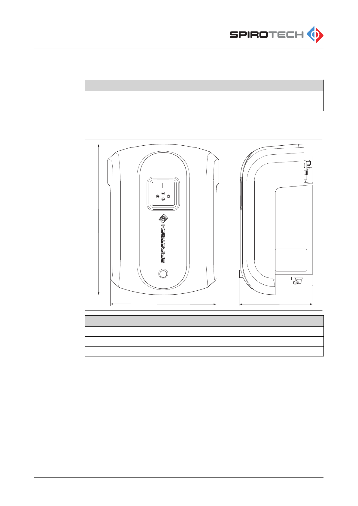
7.1 Overview of the unit.................................................................................................................... 26
7.2 Overview of the PCB of the control panel...................................................................................27
7.2.1 BMS connector (NO-C-NC)............................................................................................ 28
7.2.2 Connector of the power cable......................................................................................... 28
7.3 Wiring diagram............................................................................................................................29
7.4 Working principle of the degassing process............................................................................... 30
7.5 CE and UK CA marking.............................................................................................................. 30
7.6 Identification of the unit...............................................................................................................31
7.6.1 Type plate....................................................................................................................... 31
7.6.2 Location of the type plate................................................................................................32
8 Access to parts....................................................................................... 33
8.1 Get access to the hydraulic parts and the PCB of the control panel.......................................... 33
8.2 Remove or install the cover........................................................................................................ 33
8.3 Get access to the hydraulic parts............................................................................................... 33
8.4 Get access to the PCB of the control panel................................................................................34
9 Maintenance........................................................................................... 35
9.1 Maintenance instructions............................................................................................................ 35
9.2 Maintenance schedule................................................................................................................35
Contents
474.358_00 - 28.04.2021

9.3 Take the unit out of operation..................................................................................................... 35
9.3.1 Close the system valves................................................................................................. 36
9.3.2 Drain the unit...................................................................................................................36
9.4 Clean the Y-strainer (filter)..........................................................................................................37
9.5 Replace the automatic air vent................................................................................................... 37
10 Troubleshooting...................................................................................... 38
10.1 Troubleshooting instructions.......................................................................................................38
10.2 Function codes (warnings and errors)........................................................................................ 38
10.3 Troubleshooting table................................................................................................................. 39
10.4 Clean the spray nozzle............................................................................................................... 41
10.5 Unblock the pump.......................................................................................................................42
10.6 Clean the check valve of the outlet.............................................................................................42
10.7 Clean the venturi.........................................................................................................................43
10.8 Remove the venturi.....................................................................................................................43
10.8.1 Remove the top T-bend.................................................................................................. 44
10.8.2 Remove the pump...........................................................................................................44
10.8.3 Remove the bottom T-bend............................................................................................ 45
11 Guarantee............................................................................................... 46
11.1 Terms of guarantee.................................................................................................................... 46
12 Spare parts............................................................................................. 47
12.1 Replace a part............................................................................................................................ 47
12.2 Spare parts................................................................................................................................. 47
13 Maintenance card................................................................................... 49
14 EC Declaration of conformity.................................................................. 50
15 UK Declaration of conformity.................................................................. 51
Contents
74.358_00 - 28.04.2021 5

1 Introduction
1.1 About the unit in this document
The SpiroVent Superior S250 is an automatic vacuum degasser.
• For an overview of the unit, refer to section
7.1
.
This document applies to the product type with the article number shown below.
Type Article number Description
S250 MV02A50 Automatic vacuum degasser
1.2 Intended use
The unit removes dissolved and free gases from the water in heating and non-
condensing cooling installations. This way the unit prevents problems in the installations
that are caused by such gases.
Do not use the unit for any other purpose.
1.3 About this document
• Read the instructions before installation, commissioning and operation. Keep the
instructions for future reference.
• The original language of the document is English. All other available language
versions are translations of the original instructions.
• The illustrations in this document show a typical setup with relevant details for
instructional use only. Differences between the illustrations and the unit are possible
but do not have an effect on the comprehensibility of this document.
• This manual has been composed with the utmost care. Should, however, this manual
contain any inaccuracies, Spirotech bv cannot be held responsible for this.
1.4 Scope of the delivery
• 1x SpiroVent Superior S250
• 1x Quick installation guide (the guide includes a drilling template)
• 1x Quick reference guide
• 1x Safety instructions
• 1x Mounting set
Introduction
674.358_00 - 28.04.2021

1.5 Symbols used in this document
Throughout the instructions the following symbols can be used:
"Warning" means that personal injury or death is possible and "cau-
tion" means that serious damage to the product or environment is pos-
sible if you do not follow the instructions
"Hot parts" is used to give warning about the risk of burns.
"Electric hazard" is used to give warning about the risk of electric
shock.
“Note” is used to give additional information.
1.6 Related documents
Related document Document number
Pre-mounting instructions 74.437
Safety instructions 61.600
Quick installation guide (including drilling
template)
74.383
User manual 74.358
Product Reference Card 74.178
Introduction
74.358_00 - 28.04.2021 7

2 Safety
2.1 Safety instructions
Refer to the safety instructions document for the safety instructions and other safety
information.
Read these safety instructions prior to installation. This document is included in the
packaging and available on the website. The installation and operation of the unit must be
in compliance with the local safety and health regulations and accepted codes of good
practice.
Safety
874.358_00 - 28.04.2021

3 Technical specifications
3.1 Operating conditions
The unit is suitable for use in systems filled with clean water that may be partly
demineralized or contain additives. Use in combination with other fluids (e.g. glycol or
foaming fluids) is not allowed and may result in irrepairable damage. The unit should be
used within the limits of the technical specifications. Refer to section
3.3
. In case of
doubt, always contact the supplier.
3.2 General specifications
Item S250
Empty weight [kg] 11
Weight with water [kg] 12
Noise level [dB(A)] 41
Fluid connections Swivel G1/2"
3.3 Operating characteristics
Item S250
System pressure [bar g] 0.5 - 2.5
Working temperature [°C] (non-condensing) 15 - 70
Ambient temperature [°C] 0 - 40
Maximum system volume [m3] 5
Minimum conductivity [µS/cm] 50
3.4 Electrical specifications
Item S250
Supply voltage [V] 230 +/- 10%
Frequency [Hz] 50
Protection class IP 44
Maximum load external contact 24V 1A
Fuse 4 A (T)
Supply power connector Plug F type
Length of supply power cable [mm] 1250
Maximum power consumption [W] 145
Technical specifications
74.358_00 - 28.04.2021 9

3.5 Performance specifications
Item S250
Nominal degassing condition [bar-g] -0.5
Processing capacity [l/h] 42-74
3.6 Dimensions
Z
Y
X
Item S250
Width [mm] (X) 386
Height [mm] (Y) 524
Depth [mm] (Z) 252
Technical specifications
10 74.358_00 - 28.04.2021

3.7 Required free space around the unit
X X
Y
Y
Item S250
Required free space [mm] (X) 250
Required free space [mm] (Y) 250
Technical specifications
74.358_00 - 28.04.2021 11

4 Installation
4.1 Installation conditions
• Install the unit in accordance with the local guidelines and rules.
• Install the unit on a frost-free, well-ventilated place inside the building.
• Install the unit to a flat, closed wall that can carry the weight of the unit and the water
content. Refer to section
3.2
.
• Make sure that you maintain a minimum distance around the unit, for service and
repair. Refer to section
3.7
.
• Make sure that the user interface is always easily accessible.
• Install the unit as a bypass on the main line of the installation; preferably in the main
return line (15°C – 70°C, non-condensing).
• Make sure there is circulation in the system when the unit is running.
• Make sure that the flexible lines leave the unit at the top.
• In case of a heavily contaminated system fluid, a Spirotech SpiroTrap dirt separator
should be installed in the main return line of the installation, in front of the Superior
S250. We advise you to follow the VDI2035 guidelines regarding system water
quality.
• Make sure that the system is protected by a safety valve and check if the expansion
system has the proper dimensions. The water displacement in the unit can cause
pressure variations in the installation. Take into account a small extra net expansion
volume of 0.5 liters.
• In sound sensitive environments, please provide suitable sound dampers.
4.2 Installation instructions
1. Open the box according to the instructions on the box.
2. Position the drilling template on the wall. Refer to section
4.3
.
3. Prepare the wall mounting of the unit. Refer to section
4.4
.
4. Take the unit out of the box. Refer to the Quick Installation Guide.
Caution:
To prevent damage to the unit, do not put the unit on the ground.
Immediately install the unit to the wall.
5. Mount the unit. Refer to section
4.5
.
6. Install the branch lines. Refer to section
4.6
.
7. Connect the lines to the unit. Refer to section
4.7
.
8. Optionally, connect the BMS to the unit. Refer to section
4.8
.
Installation
12 74.358_00 - 28.04.2021

4.3 Position the drilling template on the wall
• Make sure that the conditions of the location meet the requirements. Refer to section
4.1
.
• The Quick Installation Guide is also a drilling template. Make sure that you read the
instructions first. Keep the Quick Installation Guide for future reference.
1. Position the drilling template on the
wall. Make sure the display is on eye-
height level and keep enough free
space around the unit.
2. Put the drilling template against the
wall.
a. Make sure that there is enough
free space around the drilling
template.
Note:
For the required free
space, refer to section
3.7
.
b. Make sure that the template is
leveled. Use a spirit level.
3. Attach the drilling template with tape to the wall.
4. Mark the drilling holes with a pencil.
4.4 Prepare the wall mounting of the unit
Note:
Make sure that you use the correct mounting materials for the designated
wall. Preferably use the mounting materials supplied with the unit.
1. Drill the holes at the marked
positions, with a drill size 10 mm.
2. Install the plugs.
3. Install the top screws and washers.
Note:
The screws must protrude
8 mm from the wall. This
space is necessary for the
mounting of the unit.
8 mm
13
3x
2x
Installation
74.358_00 - 28.04.2021 13

4.5 Mount the unit to the wall
Note:
To prevent damage to the unit, do not put the unit on the ground. Immediately
install the unit to the wall.
1. Mount the unit to the wall.
2. Make sure that the unit hangs
correctly on the fasteners.
3. Remove the cardboard spacers which
are placed between the components.
4. Install the bottom screw and washer.
5. Tighten the screws.
6. Check the angle of the air vent outlet.
Caution:
Make sure that the air
vent outlet is positioned
vertically.
Note:
Read the safety
instructions before
continuing the installation
steps.
90º
Installation
14 74.358_00 - 28.04.2021

4.6 Install the branch lines
1. Make two branch lines 1/2” (A) on the
side of the main line, preferably the
main return line.
2. Make sure that you connect the hoses
to the correct lines. Refer to the labels
on the line.
3. Install a full bore service valve (B) to
each branch.
Note:
In closed position, the
valves isolate the unit
from the system. Keep the
valves closed until the unit
is put into operation.
4.7 Connect the lines to the unit
Note:
For easy connection, the inlet and outlet lines are labeled. Make sure that you
connect the correct lines together.
1. Connect the supply line (A) to the
flexible inlet line (B).
2. Connect the return line (C) to the
flexible outlet line (D).
4.8 Connect the BMS to the unit (optional)
1. Open the control panel. Refer to section
8.3
.
2. Remove the backplate of the control panel. Refer to section
8.4
.
3. Guide the BMS cable into the unit. Refer to section
4.8.1
.
4. Connect the BMS cable to the control panel. Refer to section
4.8.2
.
5. Install the backplate of the control panel.
6. Close the control panel.
B
A
B
A
D
C
A
B
Installation
74.358_00 - 28.04.2021 15

4.8.1 Guide the BMS cable into the unit
1. Guide the BMS cable along the power
cable (A).
Caution:
Make sure that the cables
do not touch hot parts.
4.8.2 Connect the BMS cable to the control panel
For location of the connector, refer to section
7.2
.
1. Connect the BMS cable to the BMS
pins (A) of the connector of the
remote monitoring connections.
A
RS485 DI NO - C - NC
A
1
8
7
6
5
4
3
2
Installation
16 74.358_00 - 28.04.2021

5 Commissioning
5.1 Commissioning instructions
1. Fill the unit.
a. Open the inlet line. Refer to section
5.2
.
b. Deaerate the unit. Refer to section
5.3
.
c. Open the outlet line. Refer to section
5.4
.
2. Activate the unit. Refer to section
5.5
.
3. Install the cover. Refer to section
8.2
.
4. If it is required, change a setting. Refer to section
6.5
.
5.2 Open the inlet line
1. Open the inlet valve (A).
2. Do a check for leakages in the
connections.
Note:
If there is a leakage, solve
the problem.
5.3 Deaerate the unit
1. Open the control panel.
2. Open the deaeration valve.
Warning:
• Hot parts
• Be careful, the liquid
medium can be hot.
3. Close the deaeration valve as soon
as water comes out of the valve.
4. Close the control panel.
A
Commissioning
74.358_00 - 28.04.2021 17

5.4 Open the outlet line
1. Open the outlet valve (A).
5.5 Activate the unit
Caution:
Make sure that the wall socket is grounded.
Note:
Please find more details on the user interface in section
6.1
.
1. Connect the power cable to the power
supply.
Warning:
• Risk of electric shock
• Do this step carefully.
The display shows a green status
indicator LED and the current system
pressure.
2. Push the start button.
The unit is correctly activated when
the display shows these indicators:
• Green status indicator LED
• Status digit: A
• Pressure digits: -.5
Note:
If the display shows an error indication, solve the problem. Refer to
section
10.3
.
A
Commissioning
18 74.358_00 - 28.04.2021

6 Operation
6.1 User interface description
6.1.1 Overview of the user interface
E
D
C
B
F
G
A
A Status indicator LEDs
B Pressure / item value digits
C Start / scroll-up button
D Power / enter button
E Stop / scroll-down button
F Menu button
G Status / item number digit
Item Situation Function Reference
Status indicator
LEDs
Process and menu Show the status of
the unit
6.1.3
Buttons Process and menu To control the unit
6.1.2
Status / item number
digit
Process Shows actual oper-
ating mode
6.1.4
Menu Show item number
in the menu
6.1.12
Pressure / item val-
ue digits
Process Show the actual sys-
tem pressure [bar]
-
Menu Show the item value
of the user setting /
menu item
6.1.12
Operation
74.358_00 - 28.04.2021 19

6.1.2 Buttons and indicators
Item Button / indicator Function
Start / scroll-up button • To start the process
• To go up during navigation
• To increase a value
Stop / scroll-down button • To stop the process
• To reset the function code (hold
for 3 seconds)
• To go down during navigation
• To decrease a value
Power / enter button • To start up the unit
• To shut down the unit (hold for 3
seconds)
• To select a menu item
• To save a setting
Menu button • To go into in the menu
• To go out of the menu
6.1.3 Color codes of the status indicator LEDs
Color Position Status
Green Left OK
Orange Middle Warning
Red Right Error
6.1.4 Operating modes
Status / item number digit Operating mode Reference
[ ] (blank) Standby -
A Active degassing mode Section
6.1.4.1
P Pump test mode Section
6.1.4.2
F Function codes (warning or error) Section
10.2
Active degassing
The unit will start degassing either manually or automatically:
• Automatically at the daily start time
• Manually press the [start] button
In degassing mode the display will show status letter A and the vessel pressure. After the
daily runtime the degassing will stop.
High Performance Mode
After commissioning the High Performance Mode will automatically be activated. The
default daily start time is 8:00 AM and the default degassing run time is 8 hours a day.
According to user preference the daily start time (no. 1 in the menu list) and degassing
running time (no. 2 in the menu list) is adjustable. The maximum daily degassing run time
is 20 hours.
Operation
20 74.358_00 - 28.04.2021
This manual suits for next models
1
Table of contents
Popular Water System manuals by other brands

Sunbank
Sunbank SB-40G installation manual

Lubing
Lubing TwinClean Line Assembly instructions

AquaPur
AquaPur VALROM Espresso 600GPD manual

BeaconMedaes
BeaconMedaes MAT-S Installation, operation and maintenance instructions

GRE
GRE SIMPLEO 120 AR2085 Installation and maintenance manual

Culligan
Culligan LC-50 Series owner's guide

Riello
Riello Dialog Plus 300 instruction manual

VWR
VWR 171-1247 instruction manual

rbd instruments
rbd instruments UVB-100 Operation manual

Sears
Sears 390.250095 owner's manual

Global Water Solutions
Global Water Solutions PressureWave Series Installation and operating manual

Kenmore
Kenmore 625.381560 owner's manual