Alpha SolarSmart 150 User guide

Installation and Servicing
Instructions
Alpha SolarSmart 150
Pre-Heat Drain Back Solar System and Unvented Hot
Water Solar Cylinder
for use with an Alpha Combination Boiler
NepicarHouse,LondonRoad,
WrothamHeath,Sevenoaks,
Kent TN157RS
ForTechnical help or for Service call ...
ALPHAHELPLINETel:08448718764
website:www.alpha-innovation.co.uk
Leave these instructions with the User
Building Regulations Approved
Certificate No. ETC11206
SOLAR Key Mark Certificated
THE NATIONAL FEDERATION OF
ROOFING CONTRACTORS LIMITED
For latest prices and delivery to your door visit MyTub Ltd - www.mytub.co.uk - [email protected] 0844 556 1818

2Alpha SolarSmart 150 - Contents/Introduction
CONTENTS
1 Introduction ....................................... 2
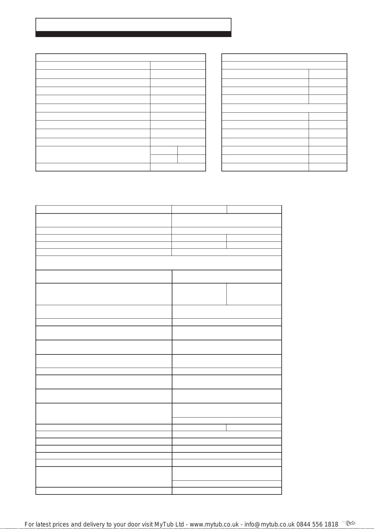
2 Technicaldata ................................... 3
3 Generalinformation ............................ 6
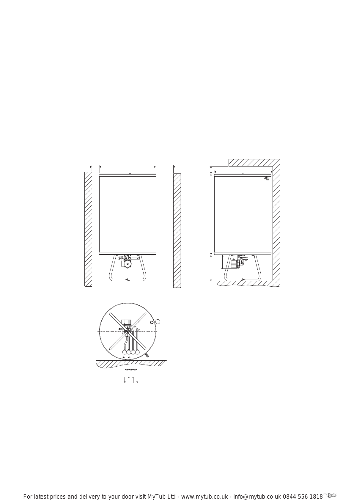
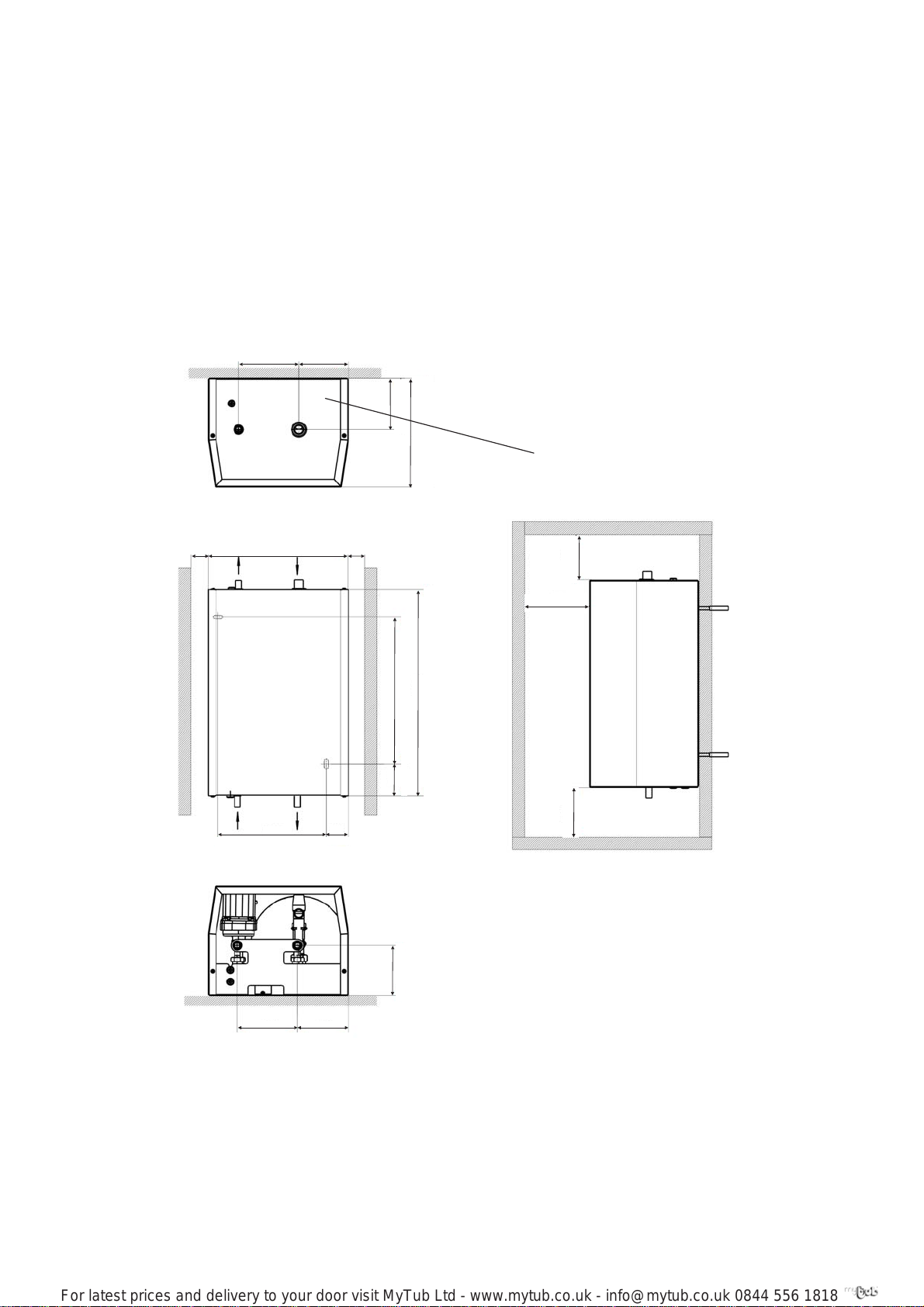
4 Installation......................................... 12
5 Commissioning.................................. 17
6 Systemoperation............................... 19
7 Routineinspection ............................. 21
8 Componentreplacement .................... 21
9 Wiringdiagram ................................... 23
10 Diagnostics and fault codes ............... 24
11 Checklistforunventedstorage ........... 25
12 Parts list............................................ 26
13 Inspection history .............................. 27
The Alpha SolarSmart 150 system is a pre-heat drain back solar collector system which includes a floor standing 150
litre unvented cylinder to store water heated by the solar collector. The system must be used in conjunction with an
Alpha combination boiler fitted with the Alpha Solar valve which is supplied with the system.
The SolarSmart 150 system consists of a 150 litre cylinder, a flat plate drain back solar collectors, drain back unit,
unvented kit and solar valve. The 150 litre unvented cylinder is fitted with a pump and temperature sensors and is
supplied with a surface mountable control box. The drain back unit is fitted with a heat exchanger and pump.
The unvented kit must be fitted in the mains water supply to the cylinder. The kit includes a pressure reducing valve,
expansion vessel, expansion relief valve, check valve and a tundish. The solar valve must be fitted directly to the mains
water inlet of the Alpha combination boiler.
Note: In the northern hemisphere solar collectors should ideally face South. For more information see Section 3.6.
The solar collector is supplied in special packaging to protect it during transit. The four corners are protected with EPS
(polystyrene) caps and the exposed edges are protected with cardboard. The glass front and aluminium back panel are
exposed. The packaging is not intended to support the full lift weight of the collector.
When manually carrying the collector, always hold the exposed edges and not the packaging alone. The collector can
be lifted both horizontally and vertically.
The collector can only be carried using the lifting forks when on the original wooden pallet base.
IMPORTANT
This System has been approved to the Building Regulations for unvented hot water storage systems and the Local
Authority must be notified of the intention to install. Therefore the installation must be carried out by a person competent
to install unvented hot water systems.
The installation must be carried out in accordance with the following recommendations:-
All current Building Regulations issued by the Department of the Environment, i.e. Approved Document L1
Building Standards (Scotland) (Consolidation) Regulations issued by the Scottish Development Department
UK Water Regulations/Byelaws (Scotland)
Health & Safety Document No. 635 (The Electricity At Work Regulations 1989)
The installation should also be in accordance with the following British Standard Codes of Practice:-
BS 5449:1990 Forced circulation hot water systems
BS 5546:2000 Installation of hot water supplies for domestic purposes
BS 5918:1989 Solar heating systems for domestic hot water
BS 6700:2006 Design, installation, testing and maintenance of services supplying water
Failure to install this appliance correctly could lead to prosecution and will invalidate the guarantee. It is in your own
interest and that of safety to ensure that the law is complied with.
Manufacturer's instructions must NOT be taken in anyway as over-riding statutory obligations.
This appliance meets the requirements of IPX4D, i.e. degree of protection against moisture.
Reference should be made to Criteria for gas fired combination boilers used as after heaters in solar thermal systems
and BRE Solar heating UK:1981.
LightningProtection
Refer to BS6651 for lightning protection, however this does not give specific requirements for solar panels and
generally collectors mounted on non-metallic roof structures will not require lightning protection.
Advice should be sought if mounting on metallic roof structures or mounting in situations where the risk of strikes are high.
1 INTRODUCTION
For latest prices and delivery to your door visit MyTub Ltd - www.mytub.co.uk - [email protected] 0844 556 1818

3
Min. 1.0
Min. 0.22
2 TECHNICAL DATA
Alpha SolarSmart 150 - Technical Data
2.2 SOLAR COLLECTOR SYSTEM - Per Panel
Max.18.0
Max. 4.0
2.1 DHWSYSTEM
5.5 bar
12 bar
0.1 bar
15 mm
15 mm
152 L
12 L at 2.5 bar
2.5 bar
90°C/7 bar
6 bar
70°C (158°F)
Solar Cylinder
Max. Hot Water Working Pressure
Max. Mains Inlet Pressure (inlet of pressure reducing valve)
Min. Mains Water Pressure
Mains Inlet Connection
DHW Outlet Connection
DHW Cylinder Capacity
Expansion Vessel Size (pre-charge press.)
Pressure Reducing Valve Setting
Temperature and Pressure Relief Valve
Expansion Relief Valve Setting
Flow Rate L/min
gal/min
Max. Outlet Water Temp. (Approx.)
15 mm
15 mm
8 bar
0.32 L
15 mm
22 mm
6 bar
11 L
9 L
110 W/K
6 bar
Drain Back Unit (DBU)
DHW Circuit:
Flow Connection
Return Connection
Max. Working Pressure
Plate Heat Exchanger Content
Collector Circuit:
Flow Connection
Return Connection
Max. Working Pressure
Vessel Size
Max. Filled Content
Heat Transfer Capacity
Expansion Relief Valve
Reference to WRC-NSF Test Procedure 1.50.220 using a 30 kW boiler. Time to reheat water store by 55°C - 25
minutes. Reheat time for 70% of store - 18 minutes Note: Copper pipe MUST be used between the
cylinder, drain back unit and collectors.
2.5
2.26
45 Gross - 44 Nett
8
95
5
4
Aluminium Pressing
50
0.037
Aluminium Black Powder Coated
10 k
12 mm
15 mm
5.4 GJ/yr (1500 kWh/yr) (2 panels)
74%
3.629
0.9
@80 l/h - 9 kPa
Same as Supporting Roof Structure
Wind Speed 27 m/s - Snow Load 1.9 kN/m2
4 x 2.3 m2= 9.2 m2
Landscape
1120 x 2230 x 92
1.10
1030 x 2140 x 0.5
30° Min (90° Max)
Portrait
2230 x 1120 x 92
1.16
2140 x 1030 x 0.5
20° Min (90° Max)
Type:
Dimensions
Total Surface Area m²
Aperture Area m²
Length x Width x Thickness mm
Water Content L
Lift Weight kg
Hydraulics
Maximum Pressure bar
Absorber
Aluminium Cover and Copper Pipe
(Length x Width x Depth) mm
Spectral Selective Layer
Absorption Coefficient %
Emission f %
Glass
Transparent, Hardened - Thickness mm
Collector Housing
Material
Insulation
Thickness mm
Thermal conduction coefficient W/mk
Cover Frame
Material
Temperature Sensor
Type - NTC Ohm
Connections
Pre-mounted Flexible Hoses Return to DBU mm
Flow from DBU mm
Roof Slope
Energy Performance (System with 90L tank)
Zero Loss Collector Efficiency (No)
Collector Heat Loss Coefficient (a1) W/m²k
Aperture to Gross Collector Area Ratio
Collector Pressure Drop
Max. Wind and Snow Load Pitched roof
Flat roof
Max. Collector Array
Profile of collector when fitted using an Alpha flashing kit protrudes approximately 30 mm to 60 mm above the
tiles (depends upon type of tile used)
For latest prices and delivery to your door visit MyTub Ltd - www.mytub.co.uk - [email protected] 0844 556 1818

4Alpha SolarSmart 150 - Technical Data
Fig. 1
2.7 ELECTRICALCONNECTIONS
Notes: This Appliance Must Be Earthed. Do Not Connect Any Other Controls.
2.5 GENERAL2.4 ELECTRICAL
Solar Cylinder Min. Clearances for Servicing Top
Bottom
Sides
Front
DBU Min. Clearances for Servicing Top
Bottom
Side
Front
Lift Weight - Cylinder
Lift Weight DBU
Weight Full and Operational - Cylinder Assemby
Weight Full and Operational - DBU
2.3 INSTALLATION
100 mm
300 mm
10 mm
450 mm
100 mm
100 mm
10 mm
450 mm
30 kg
16 kg
190 kg
25 kg
2.6 LOCATION
Max. Height Between Top of Solar Collectors and Bottom of DBU (see Section 3.6)
Max. Height Between DBU and Bottom of Solar Cylinder 3 m
6 m
All pipework between the solar collectors, drain back unit and cylinder MUST be copper with compression fittings
on the collector to drain back circuit and compression fittings onto all cylinder connections.
Supply
External Fuse
Power Consumption Max.
Min.
230/240 V ~ 50 Hz
3 A
165 W
5 W
1330 mm
700 mm
580 mm
360 mm
280 mm
Stainless Steel
Stainless Steel
EPS Foam
100 mm
0.96 kWh/24hr
0.27 W/litre
0.033 W/mK
Zero
Zero
Steam (Water)
Solar Cylinder Dimensions Height
Dia.
DBU Dimensions Height
Width
Depth
Solar Cylinder - Material
DBU Heat Exchanger - Material
Covers/Insulation Material
Solar Cylinder Insulation Thickness
Standing Energy Loss of Solar Cylinder
Heat Coefficient of Cylinder Insulation
Global Warming Potential
Ozone Depletion Potential
Insulation Blowing Agent
For latest prices and delivery to your door visit MyTub Ltd - www.mytub.co.uk - [email protected] 0844 556 1818

5
Alpha SolarSmart 150 - Technical Data
2.8 SOLARSYSTEMSCHEMATIC
Fig. 2
1 Solar collector
2 Drain back unit (DBU)
3 DBUpump
4 DBU heat exchanger
5 Collector temperature sensor
6 Solar cylinder
7 Solar cylinder pump
8 Temperature sensors
9 Temperature and pressure relief valve
10 Control PCB
11 Overheat thermostat
12 Drain point for cylinder
13 Unvented kit
14 Expansion relief valve
15 Expansion vessel
16 Non-return valve
17 Pressure reducing valve with filter
18 Tundish
To items
9 & 14
18
14
15
16
17
Mains cold water
13
To solar cylinder
1
Cold water
inlet
3
2
4
10
Hot water
from DBU
7
Hot water to
boiler
8
8
6
5
Cold water
to DBU
9
11
12
For latest prices and delivery to your door visit MyTub Ltd - www.mytub.co.uk - [email protected] 0844 556 1818

6
3.1 ELECTRICALSUPPLY
The Solar system requires a 230/240 V ~ 50 Hz mains supply, fused at 3 A - The system must be earthed.
There must only be one common isolator, providing complete electrical isolation, for the Solar system.
This system has been fitted with a supply cable, however, if it is necessary to fit a cable use PVC insulated cable not less
than 0.75 mm² (24 x 0.2 mm) to BS 6500 Table 16. The system should be connected to a fused three pin plug and
unswitched shuttered socket outlet (both complying with BS 1363), or a fused double pole switch with a contact
separation of at least 3 mm in both poles.
Note: There is no electrical connections between the boiler and the Solar system. Therefore, it is recommended that the
Solar system electrical isolation is completely separate to the boiler and any external controls isolation.
All wiring must be in accordance with the current IEE Wiring Regulations (BS 7671).
3.2 DOMESTICHOT WATER SYSTEM
The mains water supply must be first connected to the components detailed in Section 3.3 before the Solar cylinder. No
valves must be fitted between these components and the cylinder. The incoming mains water pressure to the cylinder is
regulated to 2.5 bar by the pressure reducing valve supplied in the unvented package. However, all taps and mixing
valves used with the hot water system must be suitable for operating at a pressure of up to 8 bar.
The Solar valve, supplied in the unvented package, must always be fitted directly to the cold water inlet of an Alpha
combination boiler.
Note: The hot water control thermostat on the combination boiler must always be turned to maximum.
To ensure economic use, the pipe runs to the Alpha combination boiler and taps should be in 15 mm copper pipe and
be as short as possible. Where possible the pipework should be insulated to reduce heat loss.
Before the mains water supply pipe is connected to the boiler, it should be thoroughly flushed out to avoid the danger of
dirt or foreign matter entering the boiler and the filter incorporated within the pressure reducing valve cleaned.
The stored water temperature is controlled to a maximum of 70°C.
To prevent high temperatures at the hot water taps, it is recommended that a thermostatically controlled mixing valve is fitted
after the boiler.
3.3 UNVENTEDHOTWATERSTORAGESYSTEM
To comply with the Building Regulations for unvented hot water storage, it is required that the unvented kit components
detailed in Fig. 3 are fitted before the mains cold water inlet to the Solar cylinder. No isolating valves must be fitted
between these components and the cylinder.
All these components are supplied with the Solar system in a separate package and must be fitted by a competant
person in accordance with the instructions.
The installation is subject to Building Regulations approval and the Local Authority must be notified of the intention to install.
Discharge pipe - The discharge pipes from the temperature/pressure and expansion relief valves must be routed to the
tundish supplied and in 15 mm pipe. The discharge pipework from both relief valves may be joined together in the same
sized pipe, providing at least 22 mm pipework is connected downstream of the tundish.
Tundish-Thetundishmustbepositionedwithin500mmoftheappliance,sothatitisvisibletotheUserandawayfromelectrical
devices. The minimum size of the discharge pipe downstream of the tundish is given in the following table.
The discharge pipework from the tundish:-
3 GENERAL INFORMATION
Alpha SolarSmart 150 - General Information
1. Shall fall continuously through its length.
2. Shall be of a heat resistant material, e.g. metal.
3. Shall not be fitted with any valves or taps.
4. Shall discharge to a safe visible position, e.g. into a gulley.
5. Shall have a minimum of 300 mm straight pipework directly from the tundish.
Note: Where children may play or otherwise come into contact with discharges, a wire cage or similar guard must be
positioned to prevent contact whilst maintaining visibility.
Resistancecreated
byeachelbow
orbend
0.8m
1.0m
1.4m
Maximumresistanceallowed,
expressedasalengthofstraight
pipe(i.e.noelbowsorbends)
upto 9m
upto 18m
upto 27m
Minimumsizeofdischarge
pipe'D2'fromtundish
22mm
28mm
35mm
Minimumsizeofdischarge
pipe'D1'totundish
15mm
Valve
outletsize
G½
Sizing of copper discharge pipe 'D2' - refer also to Fig. 4A and 4B
For latest prices and delivery to your door visit MyTub Ltd - www.mytub.co.uk - [email protected] 0844 556 1818

7
Alpha SolarSmart 150 - General Information
Fig. 3
Hot tap
Combination boiler
Solar valve
Water temperature
more than 60°C
Water temperature
less than 60°C
Outlet water
temperature
60°C
Mains water
supply
Thermostat
sensor
Thermostat
sensor
Overheat
thermostat
Unvented
cylinder
Thermostat sensor
Solar collectors
(maximum of 4)
Drain back
unit
Drain back
unit pump
Cylinder
pump
Heat
exchanger
Drain
point
Thermostatically controlled
mixing valve
Cold water
supply
Filter
Pressure
reducing
valve
Check
valve
Expansion
vessel
Stop
valve
Expansion
relief valve
Expansion
relief valve
Discharge
pipe
Tundish
Unvented kit
Temperature/pressure
relief valve
For latest prices and delivery to your door visit MyTub Ltd - www.mytub.co.uk - [email protected] 0844 556 1818

8
Fig. 4b
c. Termination into a hopper
At high level, discharge onto a roof is acceptable providing the roof is capable of withstanding high temperatures and
there is a distance of 3 m from any plastic guttering systems that would collect such discharge.
Note: The discharge will consist of scalding water and steam. Asphalt, roofing felt and non-metallic rainwater goods
may be damaged by such discharges.
b. High level termination
D1
D2
300 mm
minimum
Tundish
Type'A'
air gap
Endofpipetobe
clearly visible
300 mm
minimum
Tundish
500 mm max.
Metaldischargepipe(D2)from
tundishwithcontinuousfall
Metaldischargepipe(D1)
from relief valve to tundish
Solarcylinder
temperature/pressure
relief valve
300 mm
minimum
100 mm max.
70 mm min.
Gulley if
available
Pipe close to wall to
allowwater tofan out
safely
Groundlevel
D2
D1
a. Low level termination
Toexpansion
relief valve
Worked example:-
Theexample below isfora G½temperaturerelief valvewithadischarge pipe(D2)
having four elbows and a length of 7 m from the tundish to the point of discharge.
From the table on page 6:-
Maximumresistance allowedfor a straightlength of22 mm copperdischarge pipe
(D2) from a G½ temperature relief valve is 9 m.
Subtract the resistance for four 22 mm elbows of 0.8 m each = 3.2 m.
Therefore the maximum permitted length equates to 9 - 3.2 = 5.8 m
5.8m is lessthan theactual lengthof 7m thereforecalculate thenext largestsize.
Maximum resistance allowed for a straight length of 28 mm pipe (D2) from a G½
temperature relief valve equates to 18 m.
Subtract the resistance for four 28 mm elbows at 1.0 m each = 4 m.
Therefore the maximum permitted length equates to 18 - 4 = 14 m
As the actual length is 7 m, a 28 mm (D2) copper pipe will be satisfactory.
Alpha SolarSmart 150 - General Information
Given below are suggested methods of terminating the discharge pipe safely.
Where a single pipe serves a number of discharges, such as in blocks of flats, the number served should be limited to
not more than 6 systems so that any installation can be traced reasonably easily. The single common discharge pipe
should be at least one pipe size larger than the largest individual discharge pipe to be connected.
If the system is installed where discharges from safety devices may not be apparent, i.e. in dwellings occupied by blind, infirm or disabled
people, consideration should be given to the installation of an electronically operated device to warn when discharge takes place.
Fig. 4a
For latest prices and delivery to your door visit MyTub Ltd - www.mytub.co.uk - [email protected] 0844 556 1818

9
>100 705 Dia. >300
>100 716
1002
325
169
E
50
50
51
35
ABCD
Alpha SolarSmart 150 - General Information
3.4 SOLAR CYLINDERINFORMATION-Fig.5
Positioning
The Solar cylinder must be installed on a flat horizontal surface which is capable of supporting the weight of the cylinder
when full (190 kg).
The cylinder may be installed in any room or internal space, although particular attention is drawn to the requirements of
the current IEE Wiring (BS7671) Regulations, and in Scotland, the electrical provisions of the Building Regulations
applicable in Scotland, with respect to the installation of the cylinder in a room or internal space containing a bath or
shower. When the cylinder is installed in a room containing a bath or shower, it must not be possible for a person using
the bath or shower to touch any electrical switch or cylinder control utilising mains electricity.
The bottom of the Solar cylinder must be located within 6 metres of the top of the drain back unit.
Dimensions
The dimensions of the cylinder and clearances required for servicing are shown in Fig. 5.
Water connections
Fig. 5
The connections at the bottom of the cylinder are shown in Fig. 5.
Note: Use compression fittings only on the cylinder connections and copper pipe between the cylinder and drain back
unit. We also recomend a minimum of 1 metre of copper pipe from the cylinder for the water inlet and outlet connections.
Cylinder Connections
AWater outlet to boiler 15 mm
BCold water inlet 15 mm
CReturn from DBU 15 mm
DFlow from cylinder to DBU 15 mm
ECylinder sensor
For latest prices and delivery to your door visit MyTub Ltd - www.mytub.co.uk - [email protected] 0844 556 1818

10
3.5 DRAINBACKUNIT(DBU)INFORMATION-Fig.6
Positioning
The DBU must be located within a height of 3 metres of the top of the Solar collectors, see Fig. 8. The pipework from the
collectors to the DBU must always fall by a minimum of 40 mm per metre and must be insulated with high temperature
pipe insulation.
Dimensions
The dimensions of the DBU and clearances required for servicing are shown in Fig. 6.
Water connections
The connections at the top and bottom of the DBU are shown in Fig. 6.
Alpha SolarSmart 150 - General Information
Notes: 1. Use copper pipe and compression fittings only on the pipework between the DBU and solar collectors.
2. Thetubingfromthesolarcollectorsmustalwaysslopedowntowardsthedrainbackunit(atleast40mmpermetre).
3. There must not be any part of the tubing that will allow water to collect.
4. DBU Pressure relief valve - complying with BS 6759 and set to operate at 6 bar. The discharge pipe must be
routed clear of the DBU and terminate in such a manner that it can be seen, but cannot cause injury to
persons or property.
Fig. 6
Serial number: on the
top of the housing
CD
BA
153 130
127
276 57
374
567
82
>300
>500
>100
>100
357
>100
278
131
154 126
DBU Connections
AReturn from collector to DBU 22 mm
BFlow from DBU to collector 15 mm
CFlow from cylinder to DBU 15 mm
DReturn from DBU to cylinder 15 mm
For latest prices and delivery to your door visit MyTub Ltd - www.mytub.co.uk - [email protected] 0844 556 1818

11
Alpha SolarSmart 150 - General Information
3.6 SOLAR COLLECTORINFORMATION-Fig.7
The solar energy supplied by a system varies with the orientation and tilt of the collector, which will usually be
determined by the existing roof. However, the predicted variation is slight. For a collector facing anywhere between SE
and SW and tilted upto 60° from the horizontal, the annual solar energy supplied will be at least 90% of that obtained at
the optimum collector position (South at 30°).
It should be remembered that shading from trees, buildings etc., can produce a significant decrease in system
performance, and collectors should be positioned to minimise shading from the sun.
The solar collector can be installed using one of the following methods:
a. Integration of the collector into the tiles of a pitched roof: Using the Alpha Flashing Kit (portrait or landscape),
landscape or portrait collectors can be integrated into the structure of a pitched roof as shown in Fig. 7. The roof must
have an inclination of more than 20° for portrait and 30° for landscape. The tiles used with the flashing kit must be
suitable to ensure that the installation is weatherproof. Full details of this type of installation are provided in the
instructions supplied with the kit.
b. Positioning of a landscape collector onto a flat roof: Using the Alpha Flat Roof Kit (Part No. 6.4000800), the collector is
mounted on the framework supplied. The collector is fixed at an inclination of 30° and ballast is used to secure the frame
in the required position. Refer to Fig. 8 for details of location of the drain back unit in relation to the collector. Full details of
this type of installation are provided in the instructions supplied with the kit.
1.2 m 1.2 m 1.2 m1.2 m
Max. 5 metres X
DBU
2.5 m 2.5 m
DBU
Max. 5 metres X
Collectors
Portrait
inclined
roof
Landscape
inclined
roof
Flat roof
2 X = 10m X = 10m X = 10m
3 X = 5m X = 5m X = 5m
4 X = 1m X = 1m X = 1m
Please note: All maximum distances X are under the
condition that the connecting pipework between the
individual collectors does not exceed the 5 metres !
Fig. 7
Fig. 8
Note: When fitted, the collector must be level
within 2 mm per metre.
A Preheated solar water to boiler
B Cold water inlet
C Warm solar heated water into the cylinder
D Cool water to DBU
Drain back unit
(DBU)
Roof
Max.
3m
Solar cylinder
Maximum of 4
collectors
Minimum decline of 40mm
per metre required
For latest prices and delivery to your door visit MyTub Ltd - www.mytub.co.uk - [email protected] 0844 556 1818

12
Solar cylinder
Control box
Instructions
Alpha SolarSmart 150 - Installation
4 INSTALLATION
4.1 UNPACKING
The SolarSmart 150 system is supplied in three boxes as follows:
Box 1 - Solar cylinder
Contents: Solar cylinder
Inlet pipework assembly
Temperature/pressure relief valve with discharge pipe
Cylinder pump
Cylinder stand
Control box
Fitting instructions
Box 2 - Drain back unit
Contents: Housing and drain back unit pump (with 7 metre cable)
Screw pack
Cable set for collector temperature sensor
Box 3 - Unvented kit and Solar valve
Contents: 2.5 bar pressure reducing valve
12 litre expansion vessel, pre charged to 2.5 bar
Expansion vessel mounting bracket
Tundish
6 bar expansion relief valve/check valve
Solar valve kit
Fitting instructions
The following items are also required to complete the installation:
1. Solar collectors - Landscape or Portrait
2. Solar collector mounting kits: a. Pitched roof collector flashing kits - portrait 2 to 4 panels, landscape 2 panels.
Part No. 6.4000760 - Left hand portrait kit
Part No. 6.4000780 - Right hand portrait kit
Part No. 6.4000770 - Centre portrait kit
Part No. 6.4000660 - Left hand landscape kit
Part No. 6.4000680 - Right hand landscape kit
or b. Flat roof collector mounting kit, landscape only (Part No. 6.4000800) - 2 off.
3. Alpha combination boiler and flue.
4. Thermostatic mixing valve.
5. High temperature 15 mm pipe insulation (150°C plus).
4.2 LOCATIONandCLEARANCEREQUIRED
Refer to Section 3.4, 3.5 and 3.6 before locating the solar cylinder, drain back unit and solar collector.
4.3 INSTALLTHECOLLECTOR
Refer to installation instructions supplied with the Solar collector mounting kit to install the collector.
4.4 FITTHESOLARCYLINDER
The cylinder must be installed on a flat surface which is capable of supporting the weight of the full cylinder (see
Sections 2.3 and 3.4).
Decide on the position of the cylinder, taking into consideration the clearances and the maximum allowed distances
from the drain back unit and collector. Refer to Section 2.6.
Fig. 10 - Box 2
Drain back unit
Fig. 9 - Box 1
For latest prices and delivery to your door visit MyTub Ltd - www.mytub.co.uk - [email protected] 0844 556 1818

13
Alpha SolarSmart 150 - Installation
4.5 FIT THE SOLAR CONTROL BOX - Figs. 11, 12 and 13
1. Decide upon the position of the control box which must be accessible and kept free from moisture. Ensure that the
position meets the requirements given in Figs. 11 and 12.
2. Secure the mounting bracket to the wall using two screws and plugs. See Fig. 13.
3. Remove the two screws securing the front cover. Remove the cover and secure the control box to the mounting bracket.
Replace the cover.
Fig. 11
4.6 FITTHEDRAIN BACK UNIT
The DBU must be installed on a flat vertical surface, which is capable of supporting the weight of the full DBU (see Section
2.3). The DBU should be secured in position using the fixings supplied.
To fit the DBU on wall
1. With the help of Fig. 6, decide upon the position of the unit, taking into account the clearances required around the unit.
2. Remove the front cover of the DBU (four screws - one each corner see Fig. 20).
3. Offer the DBU into position and mark the two fixing holes making sure it is level.
4. Drill and plug the holes and secure the unit to the wall, using the plugs and screws supplied.
5. The DBU will require pre-filling with water when the system is installed and pipework connected (see Commissioning
Section 5.2).
Fig. 12
Fig. 13
1.0 metre 1.5 metre
6.0 metre
230 V
wall socket
Solar
controller
Drain back unit
150 L
Solar
cylinder
At least 500 At least
100
At least
100
At least 100
For latest prices and delivery to your door visit MyTub Ltd - www.mytub.co.uk - [email protected] 0844 556 1818

14 Alpha SolarSmart 150 - Installation
4.7 FIT THE UNVENTED KIT - Fig. 14
1. Unpack Box 3 and check the contents.
2. Locate the expansion vessel mounting bracket in a suitable position as close to the solar cylinder as possible and secure
in postion using the srews and wall plugs supplied.
3. Secure the expansion vessel to the mounting bracket using the metal band, nut, washers and bolt.
Note: Ensure the pressure in the expansion vessel is 2.5 bar. If it is not, adjust the pressure to give 2.5 bar.
4. Connect the expansion relief valve to the expansion vessel as shown in Fig. 14.
Notes: a. The plug must be removed from the capped connection on the expansion vessel relief valve to enable
connection to the expansion vessel.
b. Mount the valve in either the horizontal or vertical orientation. An inverted orientation may allow debris
deposits onto the valve seating and cause the valve to malfunction.
c. Ensure the valve is mounted correctly, i.e. the arrow marking on the valve body is pointing in the direction of flow.
5. Connect the mains water supply to the pressure reducing valve and thoroughly flush out the water pipework.
Refer to Domestic Hot Water System, Sections 3.2 and 3.3.
Fig. 14
4.8 FIT THE BOILER AND THE SOLAR VALVE
1. Only an Alpha combination boiler may be
used with the SolarSmart 150 system. Install
the boiler as described in the instructions
supplied with the boiler.
2. Connect the solar valve directly to the boiler
cold water inlet connection, then connect the
pipework to the solar valve as shown in Figs.
15 and 16.
Notes: a. If the valve is being fitted to an
existing boiler installation, the
mains water inlet must be re-
routed to the inlet of the solar
cylinder's unvented kit.
b. Ensure that the hot water outlets 'B'
and 'D' (Fig. 16) are connected
together after the leaving the
boiler.
c. It is recommended that a
thermostatic mixing valve is fitted in
the hot water outlet before the taps. Fig. 15
For latest prices and delivery to your door visit MyTub Ltd - www.mytub.co.uk - [email protected] 0844 556 1818

15
Fig. 16
Alpha SolarSmart 150 - Installation
3. A self adhesive label is supplied in the
Solar Valve Kit. This label must be
located as shown in Fig. 17, over the
boiler hot water thermostat knob after it
has been set to its maximum position, i.e.
fully clockwise to position No. 9. This will
ensure that the hot water temperature
from the boiler will be approximately
60°C and will prevent the knob from
being adjusted to a lower temperature.
Note: The User must be informed of the
purpose of this label, which must not be
removed.
CD25, 28X CD25, 28X with Premier Pack
CD25, 28, 35C CD25, 28, 35C with Premier Pack
Notes:1. Join together hot water outlets B and D to provide a single hot water supply immediately after boiler installation.
2. When connecting the Solar Valve to a CDX boiler the filling loop connection of the Solar Valve must be plugged with a ½"
brass plug.
3. When connecting the Solar Valve to a CDC boiler isolate the filling loop after filling the central heating system.
23
20
M
½" Brass
plug
L
J
H
K
G
I
CB FDEA
65 70 45705895 37
N
M
Filling loop
N
23
20
CB FDEA
65 70 45705895 37
G
I
L
J
H
K
M
N
23
20
CB FDEA
65 70 45705895 37
G
I
L
O
P
J
H
K
Filling loop
A- Heating flow (22 mm)
B- Hot water outlet (15 mm)
C- Gas inlet (22 mm)
D- Hot water outlet from Solar valve (15 mm)
E- Heating return (22 mm)
F- Pressure refief valve outlet (15 mm)
G- Water inlet from Solar cylinder (15 mm)
H- Cold water inlet filter
I- Solar Valve
J- Heating return valve
K- Heating flow valve
L- Heating drain point
G
I
23
20
L
O
P
M
J
H
K
CB FDEA
65 70 45705895 37
N
½" Brass
plug
M- Condensate trap
N- Condensate discharge pipe
O- Cyclone drain point (if applicable)
P- Wall jig (if applicable)
01
2
3
1
2
3
4
5
6
7
8
9
1
2
3
4
5
6
7
8
9bar
04
3
2
1
RESET
A
D
B
C
SELECTOR THERMOSTAT THERMOSTAT
OFF
IMPORTANT
MUST
This Combi boiler is fitted to an
Alpha Solar system and the hot
water thermostat always be
set at maximum (No.9)
Fig. 17
For latest prices and delivery to your door visit MyTub Ltd - www.mytub.co.uk - [email protected] 0844 556 1818

16 Alpha SolarSmart 150 - Installation
4.9 CONNECT THE PIPEWORK - Fig. 16
1. Thoroughly flush out all the water pipework. Ensure that all the plastic caps are removed from all connections.
Note: If soldering union bends, ensure that the bends are not connected to the valves etc., otherwise the internal seals
may be damaged.
2. Connect the pipework from the unvented kit to the solar cylinder.
Note: No valves must be fitted between the cylinder and the unvented kit.
3. Connect the system pipework to the boiler and the discharge pipe to the heating system pressure relief valve.
Do not forget that the pressure relief valve discharge pipe must be routed clear of the boiler to a drain in such a manner
that it may be seen, but cannot cause injury to persons or property. Refer to the boiler instructions.
4. Connect the discharge pipework to the temperature/pressure relief and expansion relief valves via the tundish supplied.
This pipework must be installed as recommended in Unvented Hot Water Storage System, Section 3.3.
5. Ensure that all the valves are closed (spindle flats at right angles to valve) and do not turn on the water supply at this stage.
4.10 ELECTRICAL CONNECTIONS - See Fig. 18 and Refer to Wiring Diagram Section 9
1. Remove the screws from the front of the control box - hinge the bottom cover down and the top cover up to provide
access to the terminals on the control board. Refer to Section 2.7 for details of all electrical connections required.
2. Connect the Drain Back Unit pump - The drain back unit pump is fitted with a 7 metre cable. Route the cable to the solar
cylinder control box. Connect the wires as follows:
Brown wire to terminal 9, Blue wire to terminal 8 and Green/Yellow wire to .
Ensure that the cable is secured in the cable clamp (5in Fig 18).
3. Connect the Collector Sensor - The sensor has a 7 metre cable. Plug the white sensor cable into the blue connector sensor
cable and route the cable to the solar cylinder control box. Connect the White and Brown wires to terminals 2 and 3.
Ensure that the cable is secured in the cable clamp (6in Fig. 18).
Note: When using two or more collectors, only one sensor is connected to the control box - Connect the sensor from the
collector in the more shaded condition.
4. Connect the cylinder sensors to the corresponding Red and White plugs in the control box. (terminal 15). Use cable
clamp 1as shown in Fig. 18.
5. Connect the cylinder pump plug to terminal 13. Use cable clamp 2as shown in Fig. 18.
6. Connect the overheat thermostat to terminal 12. Use cable clamp 3as shown in Fig. 18.
7. Connect the Mains Supply - Refer to Sectioin 2.7.
Note: The solar cylinder has been fitted with a mains supply cable. However, if it is necessary to fit an alternative supply
cable refer to Section 3.1 and release the cable clamp (4in Fig. 18). Connect the new lead as follows:
Brown wire to L, Blue wire to N and Green/Yellow to the earth terminal.
Note: Ensure that the length of the earth wire is such that if the supply cable is pulled out of its clamp the live and neutral
wires become taut before the earth wire.
8. Connect an earth wire from the earthing screw on the cylinder pump manifold to the earth terminal in the controller.
9. Do not switch on the electrical supply at this stage.
Do not make any connections to terminals 4, 5, 6, or 7 and do not fit any other controls.
Fig. 18
Collector sensor
DBU pump
Overheat
thermostat
Cylinder
pump
Cylinder
sensors
Mains supply
230 V 50 Hz
Fused 3 Amp
Earth screw on
cylinder pump manifold
6
4
5
3
2
1
1
2
3
4
56
For latest prices and delivery to your door visit MyTub Ltd - www.mytub.co.uk - [email protected] 0844 556 1818

17
5 COMMISSIONING
Alpha SolarSmart 150 - Commissioning
5.1 FILLTHESOLARCYLINDER
1. Check that all the mains water connections are tight and any drain valves are
closed.
2. Open the mains water inlet valve. Thoroughly flush out the hot water system by
turning on all the hot water taps and allow the water to flow until no air is
present, this will automatically vent the cylinder of air. Turn off each tap.
3. It is important to vent the solar cylinder pump by unscrewing the centre cap
from the pump head (see Fig. 19) until water runs from it and then replace the
cap.
4. Isolate the mains inlet and drain the cylinder to remove any debris that may
have collected in the cylinder. Refill and vent the system as described above.
5.2 DRAINBACKUNIT
The drain back unit requires pre-filling (the drain back unit and collectors are to be filled with standard domestic water)
as follows:
1. Isolate the electrical supply to the SolarSmart System.
2. Remove the front cover from the drain back unit (four screws).
3. Remove the 22 mm return connection on the top of the drain back unit.
4. Close the ball valve on the manifold to prevent water from draining out of the cylinder (Fig. 20).
5. Remove the relief valve assembly by undoing the socket head capscrew using a 6mm Allen key (Fig. 20).
6. Carefully fill the drain back unit with 9 litres of water (use a flexible tube or funnel) until water overflows from the bottom
hole of the manifold (see Fig. 20). This indicates the correct fill level has been reached.
Note: Do not overfill.
7. Replace the relief valve assembly and 'O' ring.
8. Switch on the electrical supply and 'start up' the Solar system as described in Section 5.3.
9. Check for any leaks and replace the front cover.
It is important to prime the drain back unit pump:- unscrew the centre cap and rotate the spindle using a small
screwdriver. Replace the cap.
The ball valve fitted to the manifold is used for draining the drain back unit if required.
To drain the drain back unit remove the relief valve assembly and open the ball valve (Fig. 20).
Fig. 20
Fig. 19
Pump vent
screw
Socket head
capscrew
Relief valve assembly
Closed
Open
Pump vent
screw
Add water to 22 mm
return connection
Socket head capscrew
securing relief valve
Cover fixing screw
(one each corner)
For latest prices and delivery to your door visit MyTub Ltd - www.mytub.co.uk - [email protected] 0844 556 1818

18 Alpha SolarSmart 150 - Commissioning
5.3 TURNONTHEELECTRICALSUPPLY
1. Check that all the wiring has be correctly installed and that all the terminal connections are tight.
2. Switch on the electrical supply and the display (see Fig. 21) will show 'A1' and start to countdown from eighty to zero. During
this countdown the PCB does a self-diagnosis of all the sensors and pumps. If the collector temperature is between 10 and
130°C the drain back unit pump will run for a short period to run a test program, after which the system is ready for use.
3. When all the self-diagnostic procedures have been completed, the display will flash between the solar cylinder
temperature and the operation mode.
4. If there is enough solar light at the collector the cylinder pump will run, shortly followed by the drain back unit pump. The
drain back unit pump runs at full speed for 250 seconds to purge any air from the collector then it modulates to its
optimum speed for the collector temperature.
5.4 DISPLAY - Fig.21
The controls of the solar cylinder are able to indicate working modes on the display. The push button provides the
means to operate the cylinder. During normal operation the system can be turned on and off using the button. When the
button is held in for 5 seconds the diagnostic mode will be entered. Refer to Section 7. If the button is not touched for 5
seconds, the last mode will become active.
Displayshown Display explained
The indicates the operating mode of the solar system, on or off (onor oF).
If oF is shown the solar system is not operating, press the button to change from off to on.
Note: Always leave the system on
This is the temperature of the domestic hot water (°C) in the solar cylinder.
When the system is on and working, the display will alternate between the domestic hot
water temperature (for 4 seconds) and the operating mode (onor oF for 2 seconds).
This is the temperature of the domestic hot water (°C) in the solar cylinder.
The flashing dot in the right hand corner of the display shows that the drain back unit pump
and cylinder pump are running.
This is the temperature of the domestic hot water (°C) in the solar cylinder.
The flashing dot in the middle of the display shows that only the cylinder pump is running.
Flashing fault codes (71 to 84). Refer to Section 7 for a list of fault codes and possible
solutions.
Complete the details of the boiler installation in the Checklist in Section 12.
Fig. 21
Display
Push button
For latest prices and delivery to your door visit MyTub Ltd - www.mytub.co.uk - [email protected] 0844 556 1818

19
6 SYSTEM OPERATION
5.5 USERINFORMATION
The User must be advised (and demonstrated if necessary) of the following important points:-
1. How to turn the Solar Smart system on and off. It is recommended the system is always left on.
2. Explain what information is shown on the display and in the unusual case of a fault occurring, explain the fault codes that
may be shown.
3. How important it is for the combination boiler hot water thermostat to be left at the maximum position (No. 9) and that it is
the purpose of the label (Fig. 17) to maintain this and that the label must not be removed.
4. Show the User the position of the pressure relief valve discharge pipe.
5. Explain the importance of regular inspection to check the safe and efficient operation of the system.
6. Ensure the Checklist in Section 11 has been completed after the unit has been installed and commissioned.
7. Leave these instructions with the User for use on future calls and for recording details in the Inspection History Section
13.
Alpha SolarSmart 150 - System Operation
6.1 WORKINGPRINCIPAL-Fig.22
The solar collector uses the energy of the natural light to heat the water being circulated around the collector. When the
heated water enters the drain back unit, heat is transfer into the stored water via a heat exchanger coil. Stored domestic
hot water is pumped from the bottom of the solar cylinder through the drain back unit heat exchanger coil where it is
heated and returned to the cylinder.
When a hot water tap is turned on mains water flows into the bottom of the solar cylinder and hot water flows out of the
top towards the solar valve at the boiler. If the water from the cylinder is above 60°C the solar valve diverts the flow
directly to the tap, if the temperature is less than 60°C the valve diverts the flow through the combination boiler. When
the flow is via the combination boiler the water temperature is maintained by the boiler. As the temperature of the water
entering the boiler is higher than the normal incoming mains water, less gas is required to heat the water to the set
temperature of above 60°C thereby saving energy costs.
Fig. 22
Collector
Collector sensor
Cold water inlet
Warm water to boiler
Cool water to DBU
Warm water from DBU
Collector pump
System pump
Heat exchanger
Control PCB
Upper cylinder sensor
Lower cylinder sensor
Solar cylinder
Drain back unit
Hot water to taps
Solar valve
For latest prices and delivery to your door visit MyTub Ltd - www.mytub.co.uk - [email protected] 0844 556 1818

20 Alpha SolarSmart 150 - System Operation
6.2 OPERATION OF THE SOLARSMART SYSTEM - Fig.22
Control
When the controls detect a collector sensor temperature that is at least 10°C higher than the lower cylinder sensor and
the solar cylinder temperature is less than 65°C, the drain back unit pump will start. The pump will run at full speed for
250 seconds and then modulate between 16 and 50% of full speed to circulate water around the collector. The speed of
the pump is dependent upon the difference in the temperature between the collector sensor and the lower cylinder
sensor.
At the same time that the drain back unit pump starts the cylinder pump will start at 10% of full speed to circulate the
cylinder water through the drain back unit heat exchanger. The drain back unit pump will stop when the temperature
difference between the collector sensor and the lower cylinder sensor falls to 3.5°C or the cylinder temperature reaches
70°C. The cylinder pump will continue to run for 120 seconds to collect any excess heat from the drain back unit then it
will also stop.
When both pumps are operating, a flashing dot will be visible in the right hand corner of the display (Fig. 21). If only the
cylinder pump is running, a flashing dot will be visible in the middle of the display.
If a fault occurs, a fault code will be visible in the display. Refer to Section 7 for a list of fault codes and possible
solutions.
Temperature display
The display (see Fig. 21) will display the solar cylinder temperature (10 - 70°C) for 4 seconds followed by the operating
mode (onor oF) for 2 seconds, after which the sequence will be continually repeated.
Domestic hot water circuit
When a hot tap is opened, cold mains water enters the solar cylinder at the bottom forcing hot water out from the top to
go to the solar valve where it either goes directly to the tap or to the boiler for further heating. The cylinder pump passes
the cool water from the bottom of the cylinder through the drain back unit heat exchanger and warm water back to the
centre of the cylinder.
Collector water circuit
The drain back unit pump (See Fig. 22) is controlled by the PCB. The collector water is circulated in a closed loop
through the collector panel where it is heated then passes through the heat exchanger in the drain back unit where heat
is transferred to the domestic water from the cylinder.
Frostprotection
If the collector sensor registers a temperature less than 3°C, the temperature difference required to start the drain back
unit pump (normally 10°C) will be increased by 15° to 25°C. This will ensure that the unit will not operate in frosty
conditions (with the possibility of freezing). When the temperature rises above 3°C this temperature difference of 25°C
will remain for a further 24 hours when it returns to normal.
Pumps
If the electrical supply is on and the solar system has not operated for 24 hours, the pumps will operate automatically
every 24 hours, providing the collector temperature is above 10°C.
Overheat thermostat
In the unlikely event the temperature of the stored water in the Solar cylinder reaches 90°C, the overheat thermostat
(see Fig. 3) will operate and switch off the collector pump. If this happens the overheat thermostat will need to be
manually reset by pushing its reset button.
Alpha SolarSmart remote display unit - Part No. 6.4001100
The Alpha SolarSmart remote display unit is available as an optional accessory. This unit
allows the information and control available on the main Solar control panel to be in a place
that is more visible and accessible to the user. This is particularly useful if the solar system
is in the loft or garage.
Note: Two core cable is required to connect the display unit to the solar control box. The
Alpha SolarSmart display unit is only compatible with later versions of the SolarSmart
system. Compatibilty can be checked by looking at the PCB version label on the main
control PCB. Only version 28 (V28) onwards is compatible.
For latest prices and delivery to your door visit MyTub Ltd - www.mytub.co.uk - [email protected] 0844 556 1818
Table of contents
Other Alpha Water System manuals
Popular Water System manuals by other brands

EcoWater
EcoWater EcoWater CWF Installation and operating manual

Vaillant
Vaillant Solar hot water systems System manual

AquaPur
AquaPur VALROM Espresso 600GPD manual

Taco
Taco 00-VS instruction sheet

Water Worker
Water Worker HT6HB installation manual

Watts
Watts 909 Series INSTRUCTION, INSTALLATION, MAINTENANCE AND REPAIR MANUAL

Xstream
Xstream SOLARSTREAM installation guide

Viking Pure
Viking Pure Mini Pure VPM user manual

Julabo
Julabo CORIO CD operating instructions

Everpure
Everpure SSFM-50AC Series Specification sheet

Liberty Pumps
Liberty Pumps Pro680 Series installation manual

AmeriWater
AmeriWater RAPID RESPONSE Operation & maintenance manual