4
The Atmos 5.1 is a fully-featured stand-alone surround miking system for surround
productions in any known format.
The ASM5 surround microphone combines five microphones elements in an ideal
setup for surround recordings. Each one is directly assigned to one of the five
surround channels and can be processed discretely with the Atmos 5.1 controller. All
microphone elements are movable and their polar patterns can be set up individu-
ally, e g. to effectively compensate for disadvantageous room acoustics.
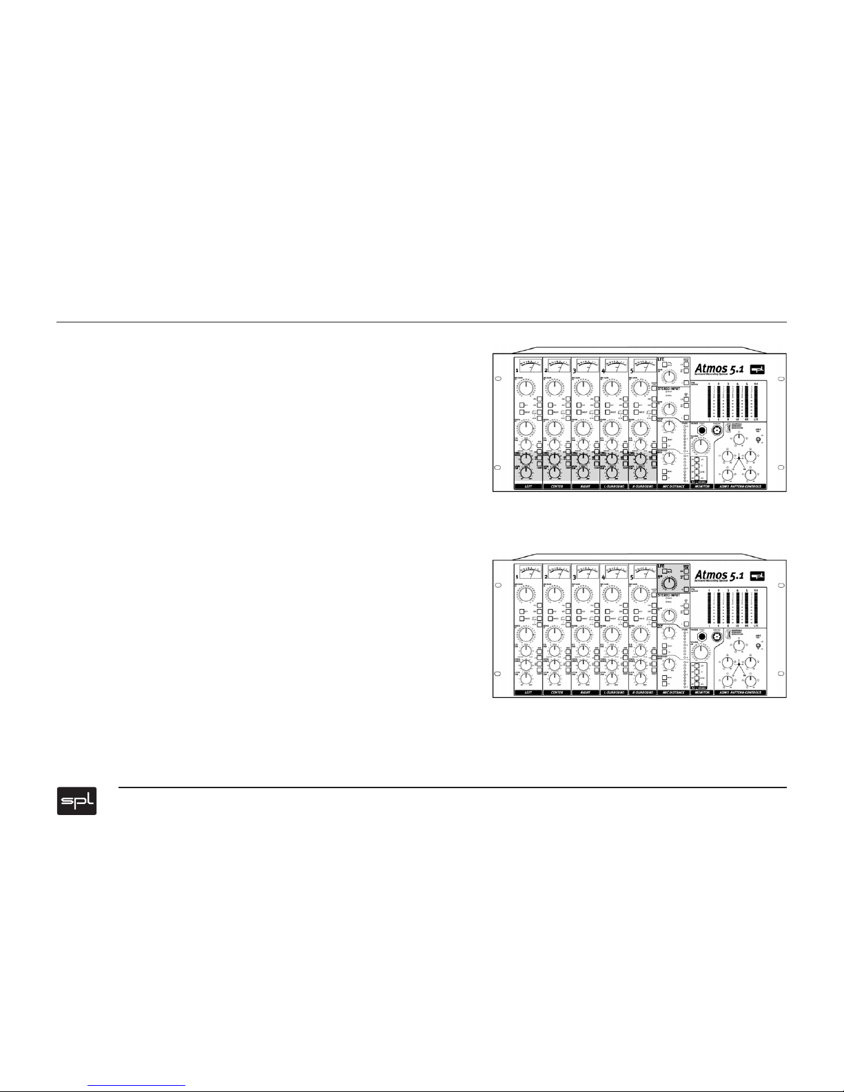
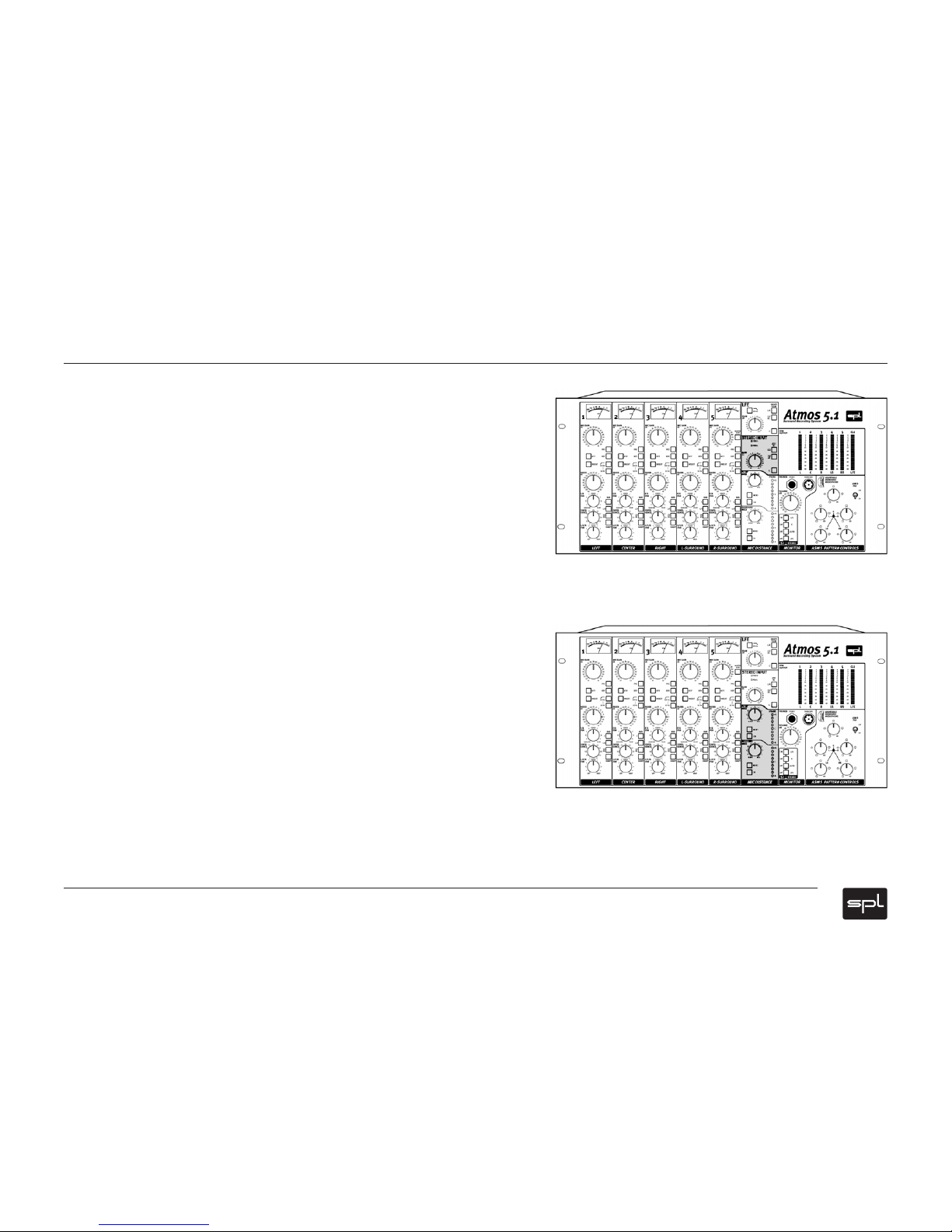
The Atmos 5.1 features a complete panorama matrix, an LFE section and a monitoring
section, thus all you need to create a surround mix. An External Inputs section allows
to integrate additional stereo mixes in a surround mix—either for the insertion of
additional microphones or to upgrade stereo consoles with surround capabilities.
The Atmos 5.1 system operates fully analog to ensure independence from any storage
or transmission format.
The ASM 5 surround microphone
The ASM 5 is based on Brauner VM1 mic elements. Three microphone elements are
assigned to the L/C/R channels, two further mics are used two capture the informa-
tion for the rear surround channels. Together they form a perfectly balanced surround
microphone.
Each microphone head can be moved by +/- 90° horizontally, the polar patterns can
be adjusted remotely from the Atmos 5.1’s ASM5 Pattern Control—infintely variable
for each capsule from omnidirectional through cardioid/hypercardioid to figure-of-
eight. A pad switch allows to reduce the microphone’s sensitivity by -16 dB.
The I/Os of both the ASM 5 and the Atmos 5.1 are built upon transformers to drive
wirings of up to 250 meters/275 yards. The ASM 5 can be installed on usual micro-
phone stands.
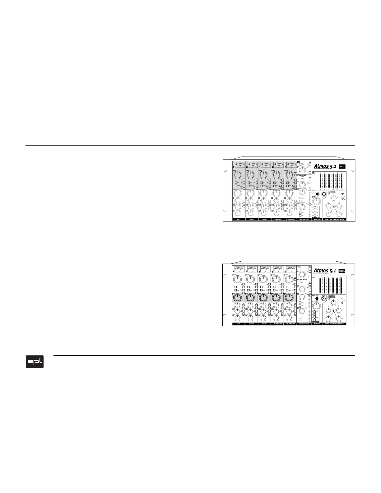
Atmos 5.1 controller
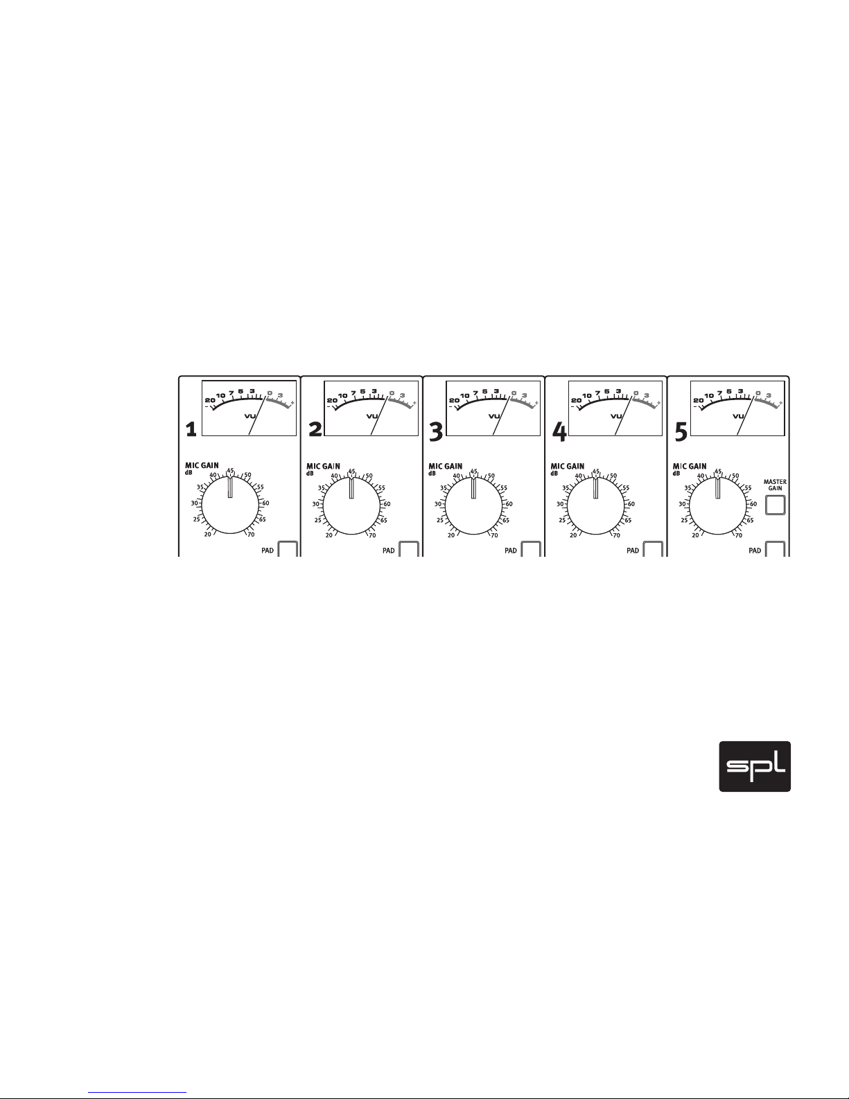
The Atmos 5.1 is equipped with five matched high precision microphone preamps
featuring SPL‘s triple gain stages to capture the superb sound of Brauner‘s ASM 5
microphone in the most transparent, noiseless and uncoloured way.
The microphone preamps also feature SPL‘s S er voD ri ve -Tec hn ology which detects
voltage differences (DC-offset) between the positive and negative paths of the ampli-
fying stages. Any offset increases noise and distortion and therefore compromises
the signal quality. ServoDrive minimizes DC-offsets to values between 0mV and 2mV.
The recorded signal contains less noise and distortion and improved tonal transpar-
ency.
Further features include Lundahl input transformers, pads, phase reverse, phantom
power, low cut filters, a switchable insert and tape send/returns. All switches are
luminated. High quality switches and relays with gold plated contacts are used
throughout.
Motorized gain controls
An important feature of the Atmos 5.1 are its motorized gain controls. While changing
the preamplification the relative loudness relationships between all five microphones
are maintained.
A Master Gain switch enables motorized control over all five microphones preampli-
fiers by just turning one control. This is especially important when re-adjustment of
the preamplification becomes necessary during recording to avoid negative effects
on the spatial coherence and phase stability.
Atmos 5.1 – the complete miking and system for surround recordings