SPOT SW 100 User manual

1
950628-04 13/11/15
IT 5 Manuale istruzione
EN 7 Instruction Manual
FR 9 Manuel d’instruction
ES 11 Manual de instrucciones
PT 13 Manual de instruções
DE 15 Bedienungsanleitung
DA 17 Brugermanual
NL 19 Handleiding
SV 21 Brukanvisning
NO 22 Instruksjonsmanual
FI 24 Käyttöohjekirja
ET 26 Kasutusõpetus
CS 34 Návod k obsluze
HU 35 Használati kézikönyv
SK 37 Návod k obsluhe
AR 53
Ташев-Галвинг ООД
www.tashev-galving.com

1
950628-04 13/11/15
TOOL
M5
M3
PowerTime
99 2
0,5
mm. N°
Power Time
0--
1
Prg.
Te st
50 10
40 4
40 2
90 2
2
95 2
3
95 3
4
95 8
5
95 10
6
95 11
7
99 12
8
99 13
9
37
2
40 --
99 3
M4
50 8
%%
N°
Prg.
99 15
10
99 16
11
99 19
12
99 22
13
99 32
14
99 35
15
0,8+
0,8+
0,8
1,0+
1,0+
1,0
1,2+
1,2+
1,2
1,5+
1,5+
1,5
2,0+
2,0+
2,0
0,5+
0,6
0,6+
0,8
0,8+
1,0
1,0+
1,2
1,2+
1,5
1,5+
2,0
2,0+
2,5
2,5+
3,0
3,0+
0,5
70 2
16
80 2
80 3
18
85 3
19
85 4
20
90 7
21
90 10
22
90 13
23
95 20
24
0,5+
0,6
0,6+
0,8
0,8+
1,0
1,0+
1,2
1,2+
1,5
1,5+
2,0
2,0+
2,5
2,5+
3,0
3,0+
17
0,5
70 2
25
80 2
90 3
27
90 4
28
95 5
29
95 7
30
99 11
31
0,5+
0,6
0,6+
0,8
0,8+
1,0
1,0+
1,2
1,2+
1,5
1,5+
2,0
2,0+
26
Air
bar
5,5
Cycle
Galvanized
High yield
Steel
Strength steel
32
33
34
35
36
37
38
39
mm. N°
PowerTime
Prg.%
Cycle
mm. N°
PowerTime
Prg.%
Cycle
psi
70
5,5
70
5,5
70
5,5
70
5,5
70
5,5
70
5,5
70
5,5
70
5,5
70
5,5
70
5,5
70
5,5
70
5,5
70
5,5
70
5,5
70
5,5
70
5,5
70
5,5
70
5,5
70
5,5
70
5,5
70
5,5
70
5,5
70
5,5
70
Air
bar
psi
5,5
70
5,5
70
5,5
70
5,5
70
5,5
70
5,5
70
5,5
70
Air
bar
psi
M3 M4 M5
37
38
39
Carbon
N°
Prg.
TOOL
36
35
34
33
32
SYNERGIC PROGRAMS
Ташев-Галвинг ООД
www.tashev-galving.com

2
950628-04 13/11/15
Fig.1
Fig.2
L
1Ph
230 V 400 V
Fig.3
Fig.4
5/7
BAR
Fig.5
E
D
A
XXXXXXX
EN XXXXX/X
XXXXXXXXXXXXXX
N.
1~xx/xxHz
xx/xxHz
I xxxx A
2cc =
(min imp)
I xxxx A
2cc =
(max imp)
Uxx /xxV
20 =
I xxxx A
2p =
F xxxx daN
max=
U xxx V
1N =
e=XXmm
S xxxx kVA
p=
L=xxx mm>xxx mm
S xxxx kVA
50% =
F xxxx daN
min=
P xxxx bar
1=
P2 xxxx bar
=
F
max
Mass xxxx Kg
=
~
=
B
C
4,1
125
34
3,1
!!
!
Fig.6.1
AIR
H2O
H2O
H2O
Earthing system IEC 60364
TN network
L1
L2
L3
N
PE
Transformer
Consumer
TT network
L1
L2
L3
N
Transformer
Consumer
TN-C network
L1
L2
L3
PEN
Transformer
Consumer
Min
2
Fig.1-a
Fig.6.2
Max ½½
123
½
1
½
3
Ташев-Галвинг ООД
www.tashev-galving.com

3
950628-04 13/11/15
Fig.8
Fig.1-a
Fig.6.3
1
2
d
b
d
a
Fig.7
(IT) LEGENDA SEGNALI DI PERICOLO, OBBLIGO, DIVIETO (EN) KEY TO DANGER, MANDATORYAND PROHIBITION SIGNS (FR) SIGNAUX DE DANGER, D’OBLIGATION ET D’INTERDICTION (ES) SEÑALES
DE PELIGRO, OBLIGACIÓN, PROHIBICIÓN (PT) LEGENDA DOS SINAIS DE PERIGO, OBRIGAÇÃO, PROIBIÇÃO (EL)(DE) GEFAHR, PFLICHTEN
UND VERBOTE HINWEISENDEN SIGNALE (DA) FORKLARING TIL ADVARSELS- PÅBUDS- OG FORBUDSSKILTE (NL) LEGENDE GEVAAR-, GEBODS-, VERBODSTEKENS (SV) TECKENFÖRKLARING
FÖR SKYLTAR FÖR FARA, OBLIGATORISKT OCH FÖRBJUDET (FI) SUURIMMAT VAARAT, PAKOLLISET JA KIELTOMERKINANNOT (ET) OHUMÄRGID, KOHUSTAVAD JA KEELAVAD MÄRGID (LV) RISKA
(LT)(PL)
(CS) (SK)
(HU)(RU) (BG)
(HR) KAZALO OPASNOSTI, ZNAKOVAOBAVEZA I ZABRANA(NO) NØKKELTIL FARE-, PÅBUDS- OG FORBUDSSKILT (SL) ZNAKI ZANEVARNOST, OBVEZNOSTI
IN PREPOVEDI (RO)(TR))
PERICOLO RADIAZIONI ULTRAVIOLETTE • DANGER OF ULTRA VIOLET RADIATION • RISQUE: RADIATIONS ULTRAVIOLETTES • PELIGRO RADIACIONES ULTRAVIOLETAS • PERIGO DE
PERICOLO SPRUZZI INCANDESCENTI • DANGER OF BURNING SPLASHES • RISQUE: JETS INCANDESCENTS • PELIGRO PULVERIZACIONES INCANDESCENTES • PERIGO DE BORRIFOS
Ташев-Галвинг ООД
www.tashev-galving.com

4
950628-04 13/11/15
PERICOLO RADIAZIONI NON IONIZZANTI • DANGER OF NON-IONIZING RADIATION • RISQUE: RADIATIONS NON IONISANTES • PELIGRO RADIACIONES NO IONIZANTES • PERIGO DE
OBBLIGO USARE MASCHERA PROTETTIVA • PROTEPROTECTIVE MASKS MUST BE WORN • OBLIGATION: UTILISER LE MASQUE DE PROTECTION • OBLIGACIÓN DE UTILIZAR MASCARILLA
OBBLIGO INDOSSARE GUANTI PROTETTIVI • PROTECTIVE GLOVES MUST BE WORN • OBLIGATION: METTRE DES GANTS DE PROTECTION • OBLIGACIÓN DE UTILIZAR GUANTES
SIKKERHEDSHANDSKER • GEBRUIK BESCHERMENDE HANDSCHOENEN VERPLICHT • SKYDDSHANDSKAR SKA BÄRAS • KÄYTÄ SUOJAKÄSINEITÄ • TULEB KANDA KAITSEKINDAID •
OBBLIGO INDOSSARE INDUMENTI PROTETTIVI • PROTECTIVE CLOTHING MUST BE WORN • OBLIGATION: PORTER DES VÊTEMENTS DE PROTECTION • OBLIGACIÓN DE UTILIZAR
VIETATO L’ACCESSO AI PORTATORI DI PACEMAKER • ENTRY NOT PERMITTED TO PERSONS FITTED WITH PACEMAKER • INTERDICTON: L’ACCÈS EST INTERDIT AUX PORTEURS DE
PACEMAKERS VERBODEN • TILLTRÄDE FÖRBJUDET FÖR BÄRARE AV PACEMAKER • PÄÄSY KIELLETTY PACEMAKERIÄ KÄYTTÄVILLE HENKILÖILLE • SISSEPÄÄS KEELATUD INIMESTELE,
•
(IT)
(EN)
(FR)
(ES)
(PT)
(DE)
(DA)
(NL)
(SV)
(NO)
(FI)
(ET)
(LV)
(LT)
(PL)
(CS)
Ташев-Галвинг ООД
www.tashev-galving.com

5
950628-04 13/11/15
IT
Manuale istruzione
Prima di utilizzare la saldatrice leggere attentamente il manuale istruzioni
Assicurati che la saldatrice sia installata e riparata da persone esperte,
Avvertenze di sicurezza
Assicurati che la presa d’alimentazione a cui colleghi la saldatrice sia protetta dai
Prima d’inserire la spina nella presa d’alimentazione, assicurati che la saldatrice sia
Spegni la saldatrice ed estrai la spina dalla presa d’alimentazione appena hai terminato
Utilizza la saldatrice solo se tutti i pannelli e schermi sono al loro posto e montati
Non utilizzare la saldatrice se è caduta oppure è stata urtata perché potrebbe non essere
Non saldare o tagliare contenitori, bombole, serbatoi o tubazioni a meno che una
sostituzione o manutenzione degli elettrodi; Regolazione della posizione di bracci o
elettrodi DEVE ESSERE ESEGUITO CON LAPUNTATRICE SPENTA E SCOLLEGATA
EMF Campi elettromagnetici
Applica i seguenti accorgimenti per minimizzare l’esposizione ai campi elettromagnetici
Fig 7 DaDb
Apparecchiatura di Classe A
Negli ambienti domestici ed in quelli collegati ad una rete di alimentazione pubblica
Saldatura in condizioni a rischio
scariche elettriche, soffocamento,
in presenza di assicurati che un responsabile
Avvertenze supplementari
Rischio residuo di schiacciamento degli arti superiori
¾
¾
è necessario predisporre attrezzature e mascheraggi atti a sostenere e guidare il pezzo
¾
(HU)
(SK)
(HR)
(SL)
(EL)
(RU)
(BG)
(RO)
(TR)
Ташев-Галвинг ООД
www.tashev-galving.com

6
950628-04 13/11/15
Fig.6.3
¾
¾
¾Non lasciare incustodita la puntatrice: in questo caso è obbligatorio scollegarla dalla
rete di alimentazione
¾
Fig.6.2
Descrizione della saldatrice
Le principali caratteristiche sono:
- scelta automatica dei parametri di saldatura
- scelta della corrente di puntatura ottimale
Organi principali Fig.1
Dati tecnici
Fig.2
saldatura
U20
I2cc (min imp)
I2cc (max imp)
I2p
U1N
Sp
S50
e
LLunghezza bracci
P1 Aria compressa: massima pressione
Messa in funzione
Assicurati che la saldatrice sia spenta e scollegata dalla presa d’alimentazione durante
Assicurati che la presa d’alimentazione a cui colleghi la saldatrice sia protetta dai
Assemblaggio ed allacciamento elettrico
¾Assembla le parti staccate contenute nell’imballo Fig.8.
¾
Sistemi TN Fig.3
¾
Sistemi TT Fig.3
¾
¾
L
L
L
¾Spina d’alimentazione
d’alimentazione una spina normalizzata (2P+T per 1Ph) di portata adeguata Fig.3.
Procedimento di saldatura
procedi nelle regolazioni Fig.1
Studder: tecnica di utilizzo
¾Collegare saldamente la sbarra di rame ad una parte del particolare in riparazione,
bloccamorsetto come nella Fig.4
L
¾Selezionare l’utensile STUDDER (1)
¾Selezionare SYNERGIC (2)
¾(4) e montarlo sulla pistola
Prg 32 > Prg 36
Puntatura Prg 37
L
Riscaldamento e ricalco lamiere Prg 38
Rappezzatura Prg 39
L
L
Puntatrici
Fig.6.1, 6.2, 6,3
preparare le punte in modo adeguato
scegliere il braccio e l’elettrodo adeguati al particolare da puntare
Collegamento della puntatrice
¾
Fig.5
Puntatura punto singolo continuo “Prg 2 > 15”
¾Selezionare l’utensile PUNTATRICE (1)
¾Selezionare SYNERGIC (2)
¾(4)
Puntatura punto singolo pulsato (per lamiere ad alto limite di nervamento o
zincate) “Prg 16 > 31”
¾Selezionare l’utensile PUNTATRICE (1)
¾Selezionare SYNERGIC (2)
¾(4)
LCOMPENSAZIONE AUTOMATICA:
il timer non esegue il punto, quindi occorre portare a nudo la lamiera su cui saldare
Test bracci
¾Selezionare l’utensile PUNTATRICE (1)
¾Selezionare SYNERGIC (2)
¾Selezionare il programma “PRG 1” (4)
occorre:
¾Selezionare SYNERGIC (2)
¾(4)
¾Selezionare MANUAL (2)
¾
utilizzando i pulsanti (3, 4).
L
TIME
Spia di segnalazione protezione termica (5)
Il generatore e l’impugnatura Studder sono dotati di protezione termica, a ripristino
.
Ташев-Галвинг ООД
www.tashev-galving.com

950628-04 13/11/15
SHOULD BE CARRIED OUT WITH THE SPOT-WELDER SWITCHED OFF AND
DISCONNECTED FROM THE POWER SUPPLY
EMF Electromagnetic Fields
Fig. 7 Da
Db
Class A equipment
Welding in conditions of risk
(electric discharges, suffocation, the
Additional warnings
¾
¾
¾
Fig.6.3
¾
¾
¾
¾
Fig.6.2
Description of the welding machine
Main parts Fig.1
Manutenzione
STUDDER
PUNTATRICI
Manutenzione straordinaria
elettromeccanico periodicamente
EN
Instruction Manual
Safety warnings
Ташев-Галвинг ООД
www.tashev-galving.com

950628-04 13/11/15
¾Position (1) on STUDDER
¾Position (2) on SYNERGIC
¾(4)
Prg 32 > Prg 36
Prg 37
L
Prg 38
Patching Prg 39
L
L
Spot welder
Fig.6.1, 6.2,
6,3
Prepare the tips correctly
Check tip alignment
¾
Fig.5
Continuous single point spot-welding “Prg 2 > 15”
¾Position (1) on SPOT WELDER
¾Position (2) on SYNERGIC
¾(4)
Pulsating single point spot-welding “Prg 16 > 31” (for sheet metal with a high yield
point or galvanized steel)
¾Position (1) on SPOT WELDER
¾Position (2) on SYNERGIC
¾(4)
L
Test for adjusting spot-welder arms
¾Position (1) on SPOT WELDER
¾Position (2) on SYNERGIC
¾Select the program “PRG 1” (4)
Revision of preset programs
¾Position (2) on SYNERGIC
¾(4)
¾Position (2) on MANUAL
¾
buttons (3, 4)
L
Thermal cutout signal (5)
Maintenance
STUDDER
Torch = check that there are no cuts or abrasions in the cable that bare the internal
SPOT WELDERS
Cables = check that there are no cuts or abrasions in the cable that bare the internal
checks
Extraordinary maintenance
mechanics periodically
Technical data
Fig. 2
B
U20
I2cc (min imp)
I2cc (max imp)
I2p
U1N
Sp
S50
e
LArms length
Fmax
Fmin
P1
P2
Mass Weight
Starting up
Assembly and electrical connections
¾Fig.8.
¾
TN systems Fig.3
¾
TT systems Fig.3
¾
¾
L
L
L
¾Plug(2P+T for
1Ph)Fig.3.
Welding process
FIG.1
Studder: tecnique for use
¾
the
LFor repairing doors or cases, it is necessary to connect the copper bar to the part, to
Ташев-Галвинг ООД
www.tashev-galving.com

950628-04 13/11/15
Fig 7 DaDb
Appareillage de Classe A
Soudage en situations de risque
S’il est nécessaire de souder en situations de risque (décharges électriques,
suffocation, en présence de, s’assurer qu’un
Avertissements supplémentaires
S’assurer qu’elle ne peut pas se
Risque résiduel de pincement des membres supérieurs
¾
¾
¾
Fig.6.3
¾
¾
¾
¾
Fig.6.2.
Description de la soudeuse
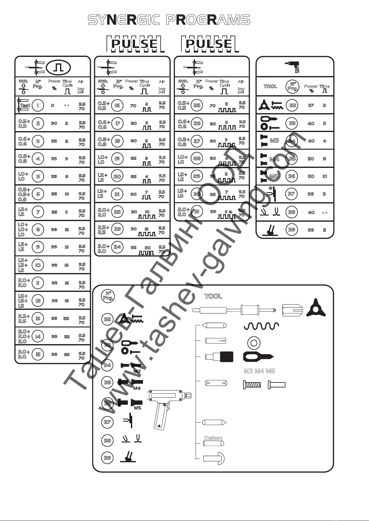
Les caractéristiques principales sont :
- la sélection automatique des paramètres de soudage
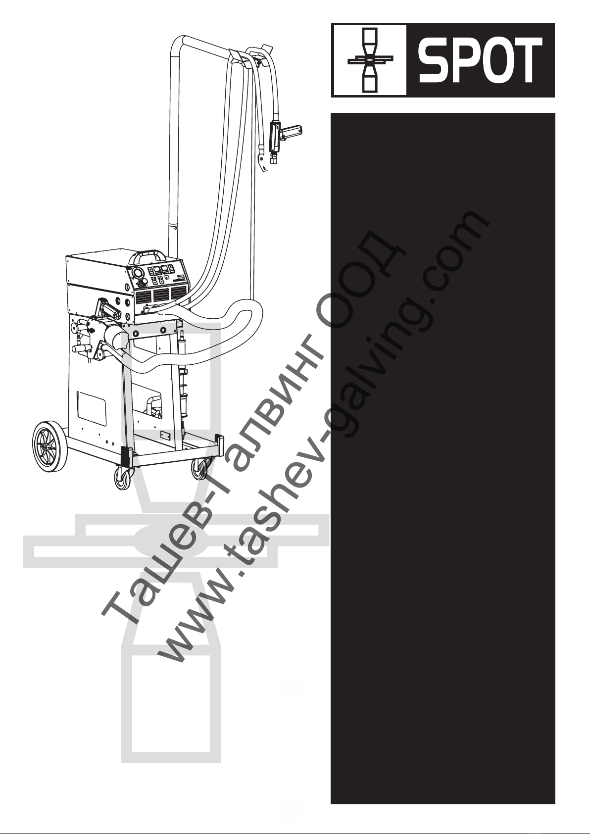
Principaux organes Fig.1.
FR
Manuel d’instruction
Les appareils de soudage par resistance, ci-dessous appelés “soudeuse”, ont été conçus
S’assurer que la soudeuse ,
soudage par résistance, sur les mesures de protection correspondantes ainsi que sur
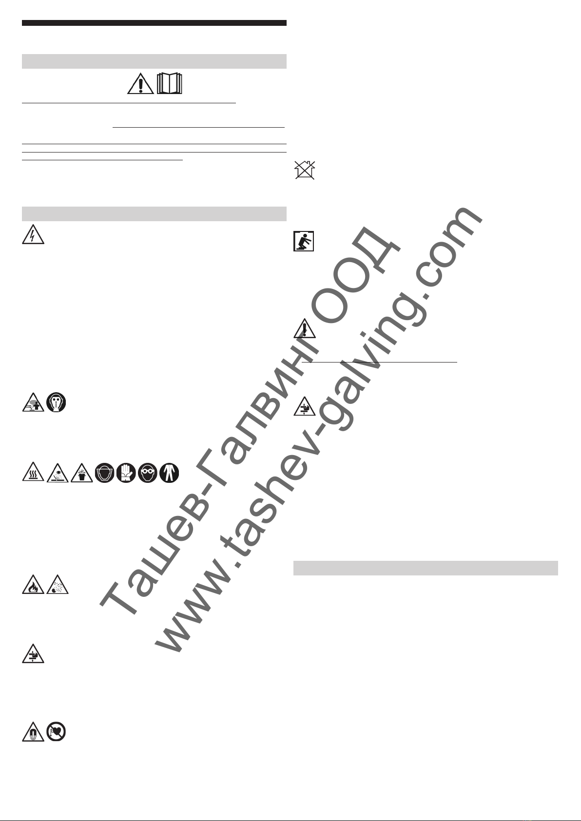
Avertissements de sécurité
le changement ou la maintenance des électrodes ; le réglage de la position des bras
EMF Champs électromagnétiques
Ташев-Галвинг ООД
www.tashev-galving.com

950628-04 13/11/15
Caractéristiques techniques
Fig.2 représente la plaque en
soudage
U20
I2cc (min imp)
I2cc (max imp)
I2p
U1N
Sp Puissance d’installation
S50 Puissance d’installation
eEspace entre les bras
LGamme de bras
Fmax
Fmin Force minimum sur les électrodes
P1
P2
Mass Poids
Mise en service
S’assurer que la soudeuse est éteinte et débranchée de la prise d’alimentation durant
Montage et raccordement électrique
¾Fig.8.
¾
Systèmes TN Fig.3
¾
¾
Systèmes TT Fig.3
¾
¾
L
L
L
¾Fiche d’alimentation
normale au câble d’alimentation (2P + T pour 1Ph)Fig.3.
Procédé de soudage
Fig.1
Studder mèthode d’emploi
¾
L
¾Selectionner l’outil STUDDER (1)
¾Selectionner SYNERGIC (2)
¾(4)
Prg 32 > Prg 36
Pointage sur un seul côté Prg 37
L
Prg 38
Rapiéçage Prg 39
L
L
pointage
Pince a souder pneumatique
Fig.6.1, 6.2, 6,3
Co
¾
Fig.5
Pointage simple point en continu “Prg 2 > 15”
¾Selectionner l’outil PINCE A SOUDER (1)
¾Selectionner SYNERGIC (2)
¾
pointée (4),
Pointage simple point par pulsations “Prg 16 > 31” (pour tôles à haute limite
d’élasticité ou galvanisée)
¾Selectionner l’outil PINCE A SOUDER (1)
¾Selectionner SYNERGIC (2)
¾
être pointée (4)
LCOMPENSATION AUTOMATIQUE
Tests pour le réglage des bras de la machine à souder par
points
¾Selectionner l’outil PINCE A SOUDER (1)
¾Selectionner SYNERGIC (2)
¾Selectionner le programme “PRG 1” (4)
¾Appuyer sur la touche (2) SYNERGIQUE
¾(4)
¾Appuyer sur la touche (2) MANUELLE
¾
(3, 4).
L
Signalisation de déclenchement thermique (L)
Entretien
STUDDER
PINCE A SOUDER
Entretien extraordinaire ,
resserrées et que l’isolant des câblages n’est pas endommagé
Ташев-Галвинг ООД
www.tashev-galving.com

11
950628-04 13/11/15
ES
Manual de instrucciones
Antes de utilizar la soldadora lea atentamente el manual de instrucciones
,
grapadora y sobre los riesgos relacionados con los procedimientos por soldadura de
Advertencias de seguridad
No suelde o corte recipientes, bombonas, depósitos o tubos a menos que una persona
EMF Campos electromagnéticos
Se deben tomar medidas de protección adecuadas en caso de usuarios de prótesis
Las personas que utilicen prótesis médicas deben consultar con el médico antes de
Fig 7 Da = cm
Db
Equipo de Clase A
Soldadura en condiciones de riesgo
En caso de tener que soldar en condiciones de riesgo, con el peligro adicional de
en presencia de,
Advertencias adicionales
.
Riesgo residual de aplastamiento de miembros superiores
¾
¾
¾
Fig.6.3
¾
¾
¾
¾
Fig.6.2
Descripción de la soldadora
por puntos en las planchas, sobre todo en las autocarrocerías y en los sectores con
Las principales características son:
Piezas principales Fig.1
Datos técnicos
Fig.2
de soldadura
Símbolo de la corriente suministrada: alterna
U20
Ташев-Галвинг ООД
www.tashev-galving.com

12
950628-04 13/11/15
I2cc (min imp) Corriente distribuida por la soldadora
I2cc (max imp) Corriente distribuida por la soldadora
I2p Corriente distribuida por la soldadora
U1N Tensión de alimentación
Sp
S50
eEspacio entre los brazos
LGama de brazos
Fmax
Fmin Fuerza mínima a los electrodos
P1
P2
Mass Peso
Puesta en funcionamiento
Ensamblaje y conexión eléctrica
¾
¾
Sistemas TN Fig.3
Sistemas TT Fig.3
L
L
LEs responsabilidad del instalador o del usuario, comprobar que pueda ser conectada
¾Enchufe de alimentación
(2P + T por 1Ph) con la capacidad
adecuada Fig.3.
Procedimiento de soldadura
soldadora, y proceda con la regulación siguiendo la secuencia indicada en la descripción
de los mandos
Studder: técnico de uso
¾
los tornillos y bornes adecuados o bien soldando a la pieza una arandela y utilizando
el bloqueador del borne como muestra la
LEn caso de reparación de puertas o cubiertas es necesario conectar la barra de cobre
¾Posicionar (1) en la posición STUDDER
¾Posicionar (2) en la posición SINERGICA
¾(4)
Soldadura por puntos y tracción arandelas especiales (arandelas
Prg 32 > prg 36
Soldadura por puntos Prg 37
L
Calentamiento y calcado de la chapa Prg 38
Remiendo Prg 39
L
L
Soldadora por puntos
Fig.6.1, 6.2, 6,3
Elegir el brazo y el electrodo adecuados a la pieza a soldar por puntos
¾
Fig.5
Punto simple continuo “Prg 2 > 15”
¾Posicionar (1) en la posición SOLDODADORA POR PUNTOS
¾Posicionar (2) en la posición SINERGICA
¾(4)
Punto simple pulsado “Prg 16 > 31” (para chapas de alto limite de
¾Posicionar (1) en la posición SOLDODADORA POR PUNTOS
¾Posicionar (2) en la posición SINERGICA
¾(4)
¾
¾Presionar el pulsador y soltarlo después que haya transcurrido el tiempo programado
LCOMPENSATION AUTOMATICA
temporizador no realiza el punto, por lo tanto es necesario limpiar la chapa sobre la
Prueba para la regulación de los brazos de la soldadora
por puntos
¾Posicionar (1) en la posición SOLDODADORA POR PUNTOS
¾Posicionar (2) en la posición SINERGICA
¾Seleccionar el programa “PRG 1” (4)
¾Posicionar (2) en la posición SINERGICA
¾(4)
¾Posicionar (2) en la posición MANUAL
¾
y utilizando los pulsadores (3, 4).
L
Indicación de accionamiento térmico (5)
Mantenimiento
STUDDER
SOLDADORA PER PUNTOS
Tubos = controlar que no haya pérdidas de aire comprimido para que no haya pérdidas
Mantenimiento extraordinario
Ташев-Галвинг ООД
www.tashev-galving.com

13
950628-04 13/11/15
PT
Manual de instruções
Antes de utilizar a soldadora ler com atenção o manual de instruções
As instalações para soldadura por resistência, a seguir chamados “soldadora”, estão
em
sobre os riscos relacionados com os procedimentos de soldadura por resistência,
Advertências de segurança
Substituição ou manutenção dos elétrodos; Regulação da posição dos braços ou
elétrodos DEVE SER EXECUTADA COM A PONTEADEIRA APAGADA E DESLIGADA
EMF Campos electromagnéticos
Fig. 7 Da =
Db
Aparelhagem de Classe A
Soldadura em condições a risco
descargas eléctricas,
sufocamento, em presença de controlar que
Advertências suplementares
Risco residual de esmagamento dos membros superiores
peça em operação impedem a realização de uma proteção integrada contra o perigo de
¾
¾
¾
Fig.6.3
¾
¾
¾
de alimentação
¾
Fig.6.2
Descrição da soldadora
As características são:
- escolha da corrente de soldadura ótima
Órgãos principais Fig.1
Dados técnicos
Fig.2
para soldadura
U20
I2cc (min imp)
Ташев-Галвинг ООД
www.tashev-galving.com

14
950628-04 13/11/15
I2cc (max imp)
I2p
U1N Tensão de alimentação
Sp
S50
eDistância entre os braços
LGama de braços
Fmax
Fmin
P1
P2
Mass Peso
Pôr a funcionar
Montagem e ligação eléctrica
¾Montar as partes separadas contidas na embalagem Fig.8.
¾
.
Sistemas TN Fig.3
Sistemas TT Fig.3
L
L
L
¾Ficha de alimentação
(2P+T para 1Ph) com capacidade adequada Fig.3.
Procedimento de soldadura
com as regulações seguindo a ordem mantida na descrição dos comandos Fig.1
Studder: técnica de utilização
¾
bloqueador de terminal como na Fig.4.
L
¾(1)
¾(2)
¾(4)
Soldadura por pontos e tracção de arruelas, pregos e rebites Prg 32
> prg 36
Soldadura por pontos Prg 37
L
Aquecimento e decalque das chapas Prg 38
Prg 39
L
L
Máquinas de soldadura por pontos
Fig.6.1,
6.2, 6,3
preparar as pontas de modo adequado
¾
Fig.5
Soldadura por pontos simples contínuo “Prg 2 > 15”
¾(1)
¾(2)
¾(4)
Soldadura por pontos simples pulsado “Prg 16 > 31” (para chapas de alto limite
de nervura ou galvanizada)
¾(1)
¾(2)
¾(4)
LCOMPENSAÇÃO AUTOMATICA
Teste braços
¾(1)
¾(2)
¾Seleccionar o programa ‘PRG 1’ (4)
¾(2)
¾
¾(2)
¾
os botões (3, 4).
L
Indicador luminoso de sinalização da protecção térmica (5)
Manutenção
STUDDER
.
Tubos = controlar a ausência de perdas de ar comprimido para não implicar em perdas
Manutenção extraordinária
electromecânico periodicamente
Ташев-Галвинг ООД
www.tashev-galving.com

15
950628-04 13/11/15
DE
Bedienungsanleitung
lesen
unter Beachtung der
Sicherheitshinweise
UND VON DER STROMVERSORGUNGABGETRENNTEM PUNKTSCHWEISSGERÄT
EMF Elektromagnetische Felder
Fig 7 DaDb
Gerät der Klasse A
In häuslicher Umgebung oder an ein Niederspannungsnetz angeschlossenen
Schweißen unter Risikobedingungen
(Stromschlaggefahr, Erstickungsgefahr,
Zusätzliche Warnhinweise
Quetschrestrisiko für die oberen Extremitäten
Abb.
6.3
Abb. 6.2
Beschreibung der Schweißmaschine
Die Hauptmerkmale sind:
Hauptbauteile Abb.1
Ташев-Галвинг ООД
www.tashev-galving.com

16
950628-04 13/11/15
Technische Daten
Abb. 2
Frequenz
U20
I2cc (min imp)
I2cc (max imp)
I2p
Einphasen-Wechselspannung; Frequenz
U1N
Sp
S50
e
LArmlängen
Fmax
Fmin
P1
P2
Mass
Inbetriebnahme
Zusammenbau und Stromanschluss
¾Die in der Packung enthaltenen Teile zusammenbauen Abb. 8
¾
Sicherung ausgestattet ist.
Systeme TN Abb. 3
Systeme TT Abb. 3
L
L
L
¾Netzstecker
ist, ist das Netzkabel an einen genormten Stecker (2P + E bei 1Ph) mit geeigneter
Abb.3.
Schweißverfahren
Abb. 1
Studder Arbeitstechnik
¾
sehen Fig.4
L
¾Wählen Sie das Werkzeug STUDDER (1)
¾Wählen das Function SYNERGIC (2)
¾(4)und montieren Sie
Nieten Prg 32 > prg 36
Prg 37
L
Prg 38
Ausbesserung Prg 39
L
L
Punktschweisser
Abb.6.1, 6.2, 6,3
¾
Fig.5
Kontinuierliches Einzelpunktschweißen “Prg 2 > 15”
¾Wählen Sie das Werkzeug PUNKTSCHWEISSER (1)
¾Wählen das Function SYNERGIC (2)
¾
¾Einzelpunkt-Pulsschweißen “Prg 16 > 31”
¾Wählen Sie das Werkzeug PUNKTSCHWEISSER (1)
¾Wählen das Function SYNERGIC (2)
¾
LAUTOMATISCHE COMPENSATION: Sollte der Massekontakt nicht ausreichend
Test zur Einstellung der Schweißerarme
¾Wählen Sie das Werkzeug PUNKTSCHWEISSER (1)
¾Wählen das Function SYNERGIC (2)
¾Wählen das Program “PRG 1” (4)
Änderung der vorgegebenen Programme
¾Wählen das Function SYNERGIC (2)
¾(4)
¾Wählen das Function MANUAL(2)
¾
(3, 4)
¾
L
¾Anzeige der Auslösung des Thermoschutzes (5)
Instandhaltung
STUDDER
PUNKTSCHWEISSER
Ташев-Галвинг ООД
www.tashev-galving.com

950628-04 13/11/15
Außerordentliche Wartung:
DA
Brugermanual
til
i
Sikkerhedsadvarsler
eksempel:
position SKAL UDFØRES MED SLUKKET SVEJSEAPPARAT, FRAKOBLET
Fig 7 DaDb
Klasse A-apparat
Svejsning under risikable forhold
(elektriske udladninger,
kvælning, antændelige eller eksplosive materialer),
Yderlige advarsler
Resterende risiko for knusning af øvre lemmer
¾
¾
¾
Fig. 6.3
¾
¾
¾
¾
Fig. 6.2
Beskrivelse af svejsemaskinen
Vigtigste dele Fig. 1
Ташев-Галвинг ООД
www.tashev-galving.com

950628-04 13/11/15
Tekniske data
Fig. 2
sikkerhed
U20
I2cc (min imp)
I2cc (max imp)
I2p
U1N
Sp
S50
e
L
Fmax Mindste
Fmin
P1
P2 mindste
Mass
Opstart
Montering og elektriske forbindelser
¾ Fig. 8.
¾
.
Ohm
L
L
L
¾Stik(2P+T
til 1Ph)Fig.3.
Svejseproces
Fig. 1
Studder: brugsteknik
¾
L
¾(1)
¾(2)
¾(4)
Prg 32 > prg 36
Prg 37
L
Prg 38
Lapning Prg 39
L
Punktsvejseapparater
Fig.6.1, 6.2, 6,3
Kontrollér, at spidsen er indreguleret
¾
Fig.5
Punktsvejsning med enkelt, kontinuerligt punkt “Prg 2 >15”
¾(1)
¾(2)
¾ / tykkelse, der skal
(4)
Punktsvejsning med enkelt, impulspunkt “Prg 16 > 31” (for metalplade med høj
strækgrænse eller galvaniseret)
¾(1)
¾(2)
¾
(4)
LAUTOMATISK KOMPENSATION
Test til justering af punktsvejsearme)
¾(1)
¾(2)
¾“PRG 1” (4)
Revision af forindstillede programmer
¾(2)
¾(4)
¾(2)
¾
trykknapperne (3, 4)
L
Signalkontrollampe for termobeskyttelse (5)
Vedligeholdelse
STUDDER
PUNKTSVEJSEAPPARATER
Ekstraordinær vedligeholdelse
Ташев-Галвинг ООД
www.tashev-galving.com

950628-04 13/11/15
Fig 7 Da =
Db
Klasse A apparatuur
Lassen onder gevaarlijke omstandigheden
elektrische
ontladingen, verstikking, ontvlambare of ontplofbare materialen
Bijkomende waarschuwingen
Restrisico van verpletting van de bovenste ledematen
¾
¾
¾
Fig. 6.3.
¾
¾
¾
¾
Fig.6.2.
Beschrijving van het lasapparaat
Hoofdorganen Afb.1
NL
Handleiding
Waarschuwingen omtrent de veiligheid
Gebruik het lasapparaat enkel indien alle panelen en schermen correct gepositioneerd
Ташев-Галвинг ООД
www.tashev-galving.com
Table of contents
Languages:
Popular Welding System manuals by other brands

Magmaweld
Magmaweld Monostick 165i user manual

Thermal Dynamics
Thermal Dynamics 38 Cutmaster operating manual

GYS
GYS PROTIG 221 DC FV operating manual

Miller Electric
Miller Electric Big Blue 400 KX owner's manual

EWM
EWM Phoenix 401 Progress puls FKG operating instructions

Schumacher
Schumacher 120V user guide

ESAB
ESAB ET180i instruction manual

Ozito
Ozito IWA-100 instruction manual

Miller Electric
Miller Electric Spectrum 3080 owner's manual

Weller
Weller WT 1 Supplementary operating instructions

Lincoln Electric
Lincoln Electric K2751-2 Operator's manual

Thermal Dynamics
Thermal Dynamics Ultra-cut 300 operating manual