2. Gasless Welding Operation
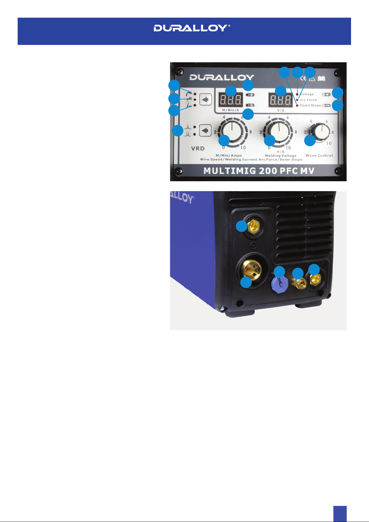
2.1 Connect the earth cable quick connector to the positive
welding power output socket (21). Connect the earth clamp
to the work piece. Contact with the work piece must be firm
contact with clean, bare metal, with no corrosion, paint or
scale at the contact point.
2.2 Change Polarity link which is situated above Wire feed system
to the Horizontal plane.
2.3 Set the welding voltage adjustment knob (2), wire speed
control knob (1) and wave control knob (15) to the desired
positions. You are now ready to weld!
3. Gas Shielded Welding Operation
3.1 Connect the earth cable quick connector to the negative
welding power output socket (17) Connect the earth clamp
to the work piece. Contact with the work piece must be firm
contact with clean, bare metal, with no corrosion, paint or
scale at the contact point.
3.2 Change polarity Link which is situated above the wire feed
system to the Vertical plane.
3.3 Assemble the female gas quick connector to the gas line
and to the regulator outlet fitting. Connect the gas regulator
to a gas cylinder (not included with machine) and connect
the female quick connector to the male gas inlet on the rear
of the machine. Ensure all connections are tight. Open gas
cylinder valve and adjust regulator, flow should be between
10-25 l/min depending on application. This can be done
by using gas purge toggle switch situated above wire feed
assembly.
3.4 Set the welding voltage adjustment knob (2), wire speed
control knob (1) and wave control knob (15) to the desired
positions. You are now ready to weld!
Note: MIG welding with aluminium provides a unique challenge, due to
the low column strength of the wire. This causes the wire to deform more
as it is pushed through the feed mechanism and the torch wire delivery
liner, greatly increasing friction. Because good MIG welding results are
dependent on a smooth wire feed, certain changes must be made to the
wire feed system to minimise friction caused issues.
For a standard ‘push’ fed torch, a length of no longer than
3m cable may be used, as well as the torch feed liner must
be changed to a special Teflon/ PVC liner, rather than the
conventional steel liner. Also the correct style drive roller must
be used and specific Aluminium rated torch contact tip (or a
standard tip in one size oversize, e.g. 0.8mm aluminium wire, use
standard 1.0mm contact tip). For this reason, it is quite common
for operators to have an extra MIG torch specifically set up for
aluminium use, if the machine is used for welding steel as well.
Another option to overcome the friction issues is using a spool
gun, which will give better results than a 3m push torch when
welding aluminium.
www.duralloy.net.au | 1300 369 456
8
MULTIMIG 200 PFC MV
OWNER’S MANUAL
4. ARC/ MMA Welding Operation
4.1 Connect the earth cable quick connector to the negative
welding power output socket (17) Connect the earth clamp
to the work piece. Contact with the work piece must be firm
contact with clean, bare metal, with no corrosion, paint or
scale at the contact point.
4.2 Insert an electrode into the electrode holder and connect the
electrode holder and work lead to the positive welding power
output socket (21).
Note: This polarity connection configuration is valid for most GP (General
Purpose) MMA electrodes. There are variances to this. If in doubt, check
the electrode specifications or consult the electrode manufacturer.
4.3 Connect the machine to suitable mains power using the mains
input power lead. Switch the mains power switch to ‘on’ to
power up the machine. Set the welding mode to MMA (4).
4.4 Select the required output current (1) and arc force (2). You are
now ready to weld!
5. Lift TIG Operation
Note: Lift TIG operation requires an optional DURALLOY TIG TORCH 174TTM , and
argon gas cylinder.
2.1 Connect the earth cable quick connector to the positive
welding power output socket (21). Connect the earth clamp
to the work piece. Contact with the work piece must be firm
contact with clean, bare metal, with no corrosion, paint or
scale at the contact point.
2.2 Insert TIG torch power connection into the negative welding
power output socket (17). Insert Aero Plug from TIG torch
into (19). This plug can only fit in 1 way, please line up prior to
fitting. Fit Gas Hose Connector on TIG torch into (18) quick
connect fitting
2.3 Open gas cylinder valve and adjust regulator, flow should
be between 5-10 l/min depending on application. Re-check
regulator flow pressure with TIG Torch Switch as static gas
flow setting may drop once gas is flowing.
2.4 Connect the machine to suitable mains power using the mains
input power lead. Switch the mains power switch to ‘on’ to
power up the machine. Select Lift TIG welding mode (5) using
the button.
2.5 Select the required output current using the current control
knob (1). Depress Button on TIG Torch ensuring 2T setting
is selected on machine. Arc will start once tungsten IS lifted
FROM THE BASE MATEREIAL.