EWM HIGHTEC WELDING TETRIX 301 COMFORT activArc User manual
EWM
HIGHTEC WELDING GmbH
Dr. Günter-Henle-Straße 8 • D-56271 Mündersbach
Fon +49 2680 181-0 • Fax +49 2680 181-244
www.ewm.de • info@ewm.de
GB
Operating instructions
Welding machines for TIG and MMA welding
TETRIX 301, 351, 421, 521 COMFORT activArc
N. B. These operating instructions must be read before commissioning.
Failure to do so may be dangerous.
Machines may only be operated by personnel who are familiar with the appropriate safety
regulations.
The machines bear the conformity mark and thus comply with the
• EC Low Voltage Directive (2006/95/ EG)
• EC EMC Directive (2004/108/ EG)
In compliance with IEC 60974, EN 60974, VDE 0544 the machines can be used in environments
with an increased electrical hazard.
©The content of the operating instructions does not constitute grounds for any claims on the part
of the buyer.
The copyright to these operating instructions remains with the manufacturer.
Reprinting, including extracts, only with written approval.
© 2009 Subject to alteration. Item No.: 099-000089-EWM01 Revised: 14.09.2009

Mündersbach, 25 February 2009
Dear customer,
Thank you for your order.
Premium quality – made in Germany and with a three-year warranty.
The machines from EWM are impressive, with innovative technology, exceptional user-friendliness and
the most up to date inverter and control systems. This makes welding possible that is simple, efficient
and resource-saving as well as being highly economical!
Perfection doesn't happen by coincidence: Every single component is 100% tested and the machine is
“free welded” before it is delivered.
Our comprehensive service offer and the highly developed modern EWM quality management system
guarantee worldwide premium quality “Made in Germany” and a three-year warranty.
Continual further development and optimisation has made us Germany’s market leader in the
manufacture of light arc welding machines. We have manufacturing, training and service locations
throughout the world to advise you and provide you with a comprehensive range of services.
The accompanying operating instructions contain everything about commissioning the machine, notes
regarding safety, maintenance and care, technical data as well as information regarding the warranty. It
is very important to observe all our instructions in order to achieve optimal welding results with the
machine and to ensure many years of safe operation.
Thank you for the trust that you have placed in us. We look forward to a long-term and, above all,
successful partnership with you.
Yours faithfully
EWM HIGHTEC WELDING GmbH
Bernd Szczesny
Executive management
Machine and Company Data
Please enter the EWM machine data and your company’s data in the appropriate fields.
CE
EWM HIGHTEC WELDING GMBH
D-56271 MÜNDERSBACH
TYP:
ART:
SNR:
PROJ:
GEPRÜFT/CONTROL:
Name of Customer / company
Adress
Post code / Place
Country
Stamp / Signature of EWM-distibutor
Date of purchase
Name of Customer / company
Adress
Post code / Place
Country
Stamp / Signature of EWM-distibutor
Date of purchase
3

Contents
Notes on the use of these operating instructions
4 Item No.: 099-000089-EWM01
1Contents
1Contents..................................................................................................................................................4
2Safety instructions.................................................................................................................................7
2.1 Notes on the use of these operating instructions...........................................................................7
2.2 General...........................................................................................................................................9
2.3 Transport and installation.............................................................................................................12
2.3.1 Lifting by crane .............................................................................................................13
2.4 Ambient conditions.......................................................................................................................14
2.4.1 In operation...................................................................................................................14
2.4.2 Transport and storage ..................................................................................................14
3Technical data.......................................................................................................................................15
3.1 TETRIX 301-521..........................................................................................................................15
4Machine description.............................................................................................................................16
4.1 TETRIX 301-521..........................................................................................................................16
4.1.1 Front view.....................................................................................................................16
4.1.2 Rear view......................................................................................................................18
4.2 Machine control – Operating elements........................................................................................20
4.2.1.1 Function sequence........................................................................................22
5Functional characteristics...................................................................................................................24
5.1 Operating concepts......................................................................................................................24
5.1.1 Manual, standard operation (JOB 0) ............................................................................24
5.1.2 Save welding tasks (JOBs)...........................................................................................25
5.1.2.1 Displaying and changing the JOB number....................................................25
5.1.3 Welding data display.....................................................................................................25
5.1.3.1 Welding parameter setting............................................................................25
5.2 TIG welding..................................................................................................................................26
5.2.1 Arc ignition....................................................................................................................26
5.2.1.1 HF ignition.....................................................................................................26
5.2.1.2 Liftarc ignition................................................................................................26
5.2.2 Automatic cut-out..........................................................................................................26
5.2.3 Function sequences/operating modes..........................................................................27
5.2.3.1 Explanation of symbols .................................................................................27
5.2.3.2 Non-latched mode.........................................................................................28
5.2.3.3 Latched mode................................................................................................29
5.2.3.4 SpotArc..........................................................................................................30
5.2.3.5 Non-latched operation, version C..................................................................32
5.2.4 Pulses, function sequences..........................................................................................33
5.2.4.1 Non-latched mode.........................................................................................33
5.2.4.2 Latched mode................................................................................................33
5.2.5 Pulse variants...............................................................................................................34
5.2.5.1 Pulses (thermal pulses).................................................................................34
5.2.5.2 KHz pulses (metallurgic pulses)....................................................................35
5.2.5.3 Automated pulses..........................................................................................35
5.2.6 TIG activArc welding.....................................................................................................36
5.2.7 Shielding gas setting.....................................................................................................36
5.2.7.1 Gas test.........................................................................................................36
5.2.8 Welding torch (operating variants)................................................................................37
5.2.8.1 Tap torch trigger (tapping function)...............................................................37
5.2.9 Torch mode and up/down speed setting ......................................................................38
5.2.9.1 Standard TIG torch (5-pole)..........................................................................39
5.2.9.2 TIG up/down torch (8-pole)...........................................................................41
5.2.9.3 Potentiometer torch (8-pole) .........................................................................43
5.2.9.4 RETOX TIG torch (12-pole) ..........................................................................44
5.2.10 Setting the first increment.............................................................................................45
5.3 MMA welding................................................................................................................................46
5.3.1 Selection and adjustment .............................................................................................46

Contents
Notes on the use of these operating instructions
Item No.: 099-000089-EWM01 5
5.3.2 Hotstart.........................................................................................................................46
5.3.2.1 Hotstart current .............................................................................................46
5.3.2.2 Hotstart time..................................................................................................47
5.3.3 Arcforce........................................................................................................................47
5.3.4 Antistick........................................................................................................................47
5.4 Key switch....................................................................................................................................47
5.5 Remote control.............................................................................................................................48
5.5.1 Manual remote control RT 1.........................................................................................48
5.5.2 Manual remote control RTP 1 ......................................................................................48
5.5.3 Manual remote control RTP 2 ......................................................................................48
5.5.4 RTP 3 manual remote control ......................................................................................48
5.5.5 Foot-operated remote control RTF 1............................................................................49
5.6 Interfaces for automation.............................................................................................................50
5.6.1 TIG interface for mechanised welding..........................................................................50
5.6.2 Remote control connection socket, 19-pole.................................................................51
5.7 Advanced settings........................................................................................................................52
5.7.1 Setting slope times for secondary current AMP% or pulse edges...............................52
5.7.2 TIG non-latched operating mode, C version................................................................53
5.7.3 Configuring the TIG potentiometer torch connection ...................................................54
5.7.4 Welding current display (ignition, secondary, end and hotstart currents)....................55
5.7.5 Ramp function foot-operated remote control RTF 1.....................................................56
5.8 Menus and sub-menus on the machine control...........................................................................57
5.8.1 Direct menus (direct access to parameters) ................................................................57
5.8.2 Expert menu (TIG)........................................................................................................57
5.8.3 Machine configuration menu........................................................................................58
6Commissioning ....................................................................................................................................61
6.1 General........................................................................................................................................61
6.2 Installation....................................................................................................................................61
6.3 Machine cooling...........................................................................................................................61
6.4 Area of application – proper usage..............................................................................................62
6.5 Workpiece lead, general..............................................................................................................62
6.6 Mains connection.........................................................................................................................63
6.6.1 Mains configuration ......................................................................................................63
6.7 Welding torch cooling system......................................................................................................64
6.7.1 General.........................................................................................................................64
6.7.2 List of coolants..............................................................................................................64
6.7.3 Adding coolant..............................................................................................................65
6.8 TIG welding..................................................................................................................................66
6.8.1 Welding torch connection.............................................................................................66
6.8.2 Connection for workpiece lead.....................................................................................67
6.8.3 Torch connection options and pin assignments...........................................................67
6.8.4 Shielding gas supply (shielding gas cylinder for welding machine).............................67
6.8.4.1 Connecting the shielding gas supply............................................................68
6.8.4.2 Setting the shielding gas quantity.................................................................69
6.9 MMA welding ...............................................................................................................................69
6.9.1 Connecting the electrode holder and workpiece lead..................................................70
6.10 PC interface.................................................................................................................................71
7Maintenance and testing.....................................................................................................................72
7.1 General........................................................................................................................................72
7.2 Cleaning.......................................................................................................................................72
7.3 Test..............................................................................................................................................73
7.3.1 Test equipment.............................................................................................................73
7.3.2 Scope of the test...........................................................................................................74
7.3.3 Visual inspection...........................................................................................................74
7.3.4 Measuring the open circuit voltage...............................................................................74
7.3.5 Measurement of insulation resistance..........................................................................74
7.3.6 Measuring the leakage current (protective conductor and contact current).................75

Contents
Notes on the use of these operating instructions
6 Item No.: 099-000089-EWM01
7.3.7 Measurement of protective conductor resistance.........................................................75
7.3.8 Functional test of the welding machine ........................................................................75
7.3.9 Documentation of the test.............................................................................................75
7.4 Repair Work .................................................................................................................................76
7.5 Disposing of equipment................................................................................................................77
7.5.1 Manufacturer's declaration to the end user..................................................................77
7.6 Meeting the requirements of RoHS..............................................................................................77
8Warranty................................................................................................................................................78
8.1 General Validity............................................................................................................................78
8.2 Warranty Declaration ...................................................................................................................79
9Operating problems, causes and remedies.......................................................................................80
9.1 Error messages (power source)...................................................................................................80
9.2 Resetting welding parameters to the factory settings..................................................................81
9.3 Display machine control software version....................................................................................82
9.4 General operating problems ........................................................................................................83
9.4.1 Interface for mechanised welding.................................................................................83
10 Accessories, options ...........................................................................................................................84
10.1 Welding torch, electrode holder and workpiece lead...................................................................84
10.1.1 TETRIX 301..................................................................................................................84
10.1.2 TETRIX 351, 421..........................................................................................................84
10.1.3 TETRIX 521..................................................................................................................84
10.2 Remote controls and accessories................................................................................................84
10.3 Options.........................................................................................................................................85
10.4 General accessories ....................................................................................................................85
10.4.1 TETRIX 301..................................................................................................................85
10.4.2 TETRIX 351-521...........................................................................................................85
10.5 Computer communication............................................................................................................85
11 Circuit diagrams...................................................................................................................................86
11.1 TETRIX 301 COMFORT..............................................................................................................86
11.2 TETRIX 351 COMFORT..............................................................................................................89
11.3 TETRIX 421 COMFORT..............................................................................................................92
11.4 TETRIX 521 COMFORT..............................................................................................................95
12 Appendix A............................................................................................................................................98
12.1 Declaration of Conformity.............................................................................................................98

Safety instructions
Notes on the use of these operating instructions
Item No.: 099-000089-EWM01 7
2Safety instructions
2.1 Notes on the use of these operating instructions
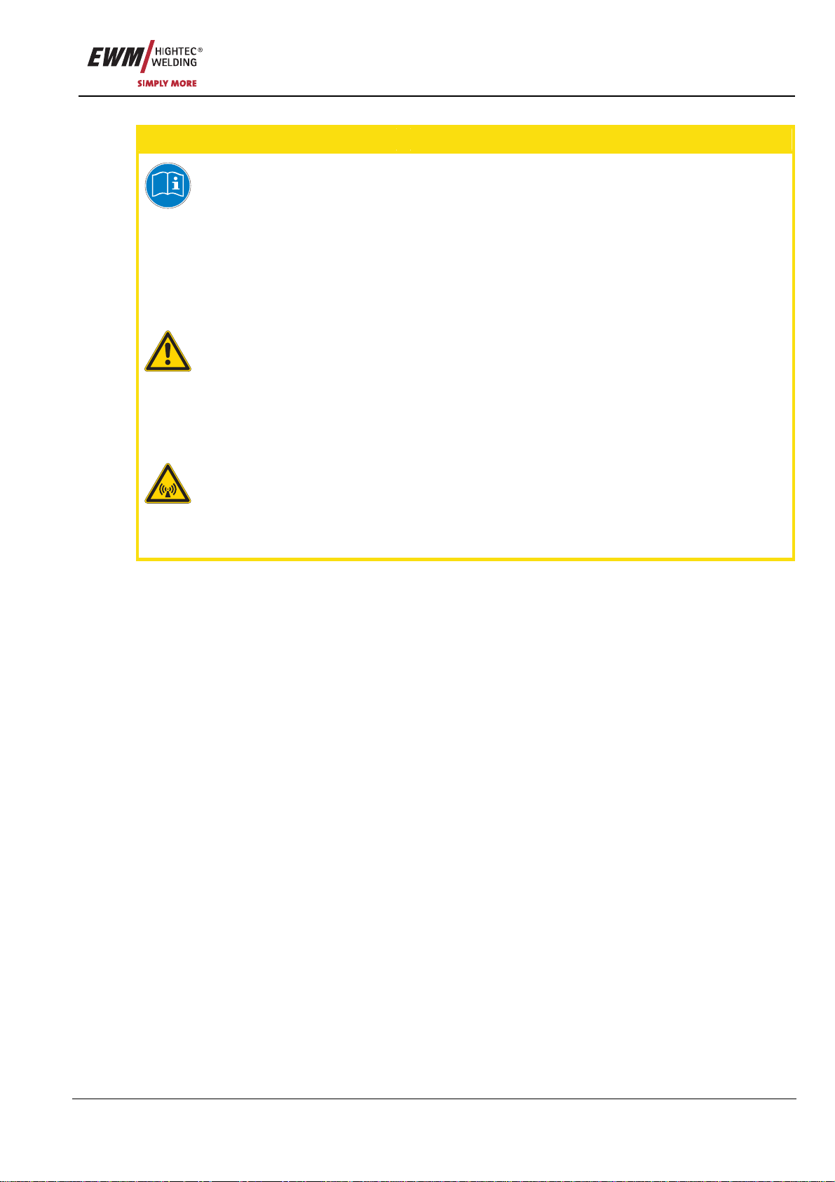
DANGER
Working or operating procedures which must be closely observed to prevent imminent
serious and even fatal injuries.
• Safety notes include the "DANGER" keyword in the heading with a general warning symbol.
• The hazard is also highlighted using a symbol on the edge of the page.
WARNING
Working or operating procedures which must be closely observed to prevent serious
and even fatal injuries.
• Safety notes include the "WARNING" keyword in the heading with a general warning
symbol.
• The hazard is also highlighted using a symbol in the page margin.
CAUTION
Working or operating procedures which must be closely observed to prevent possible
minor personal injury.
• The safety information includes the "CAUTION" keyword in its heading with a general
warning symbol.
• The risk is explained using a symbol on the edge of the page.
CAUTION
Working and operating procedures which must be followed precisely to avoid damaging
or destroying the product.
• The safety information includes the "CAUTION" keyword in its heading without a general
warning symbol.
• The hazard is explained using a symbol at the edge of the page.
NOTE
Special technical points which users must observe.
• Notes include the "NOTE" keyword in the heading without a general warning symbol.
• Notes are highlighted using a "hand" symbol at the edge of the page.
Safety instructions
Notes on the use of these operating instructions
8 Item No.: 099-000089-EWM01
Instructions and lists detailing step-by-step actions for given situations can be recognised via bullet
points, e.g.:
• Insert the welding current lead socket into the relevant socket and lock.
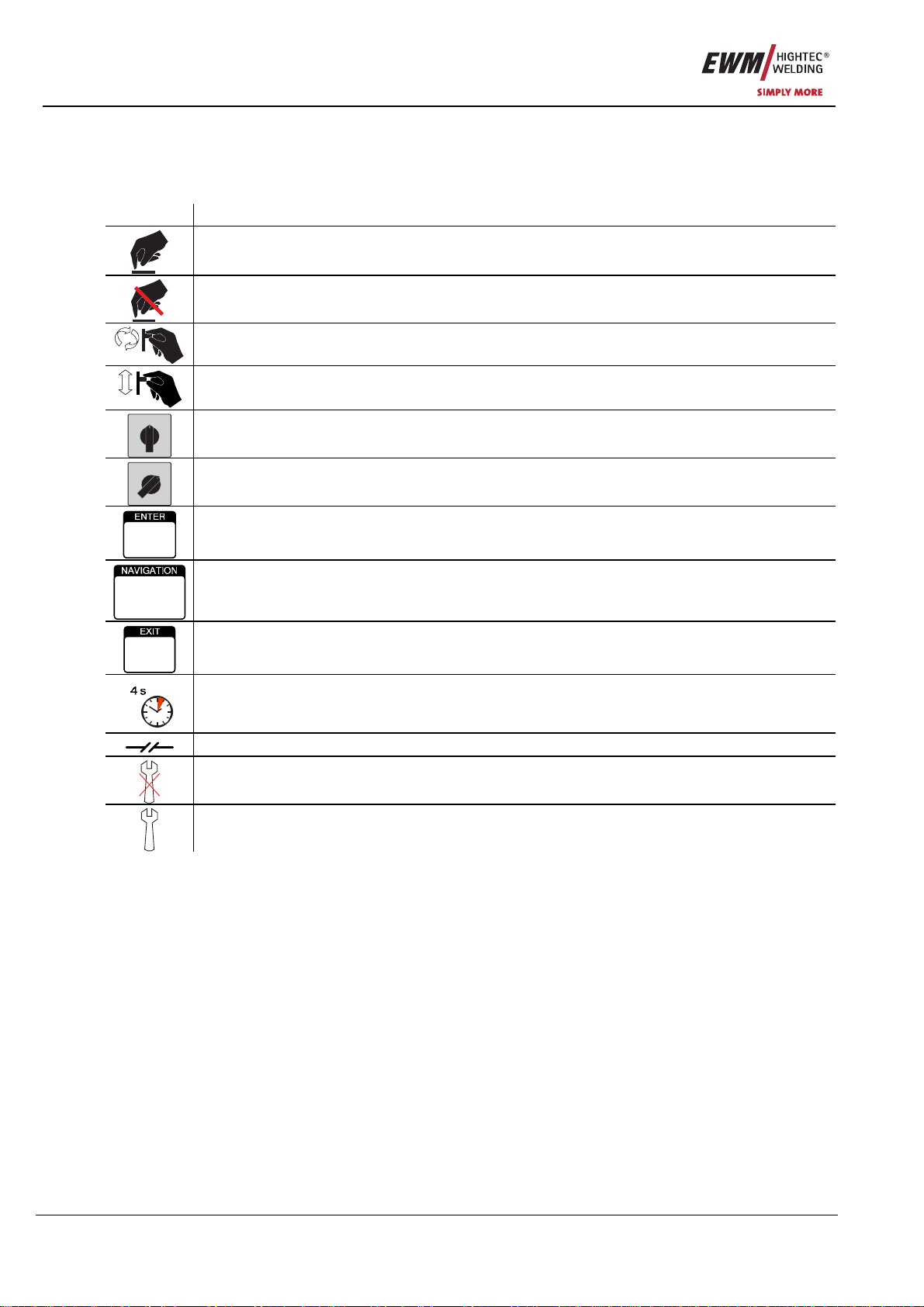
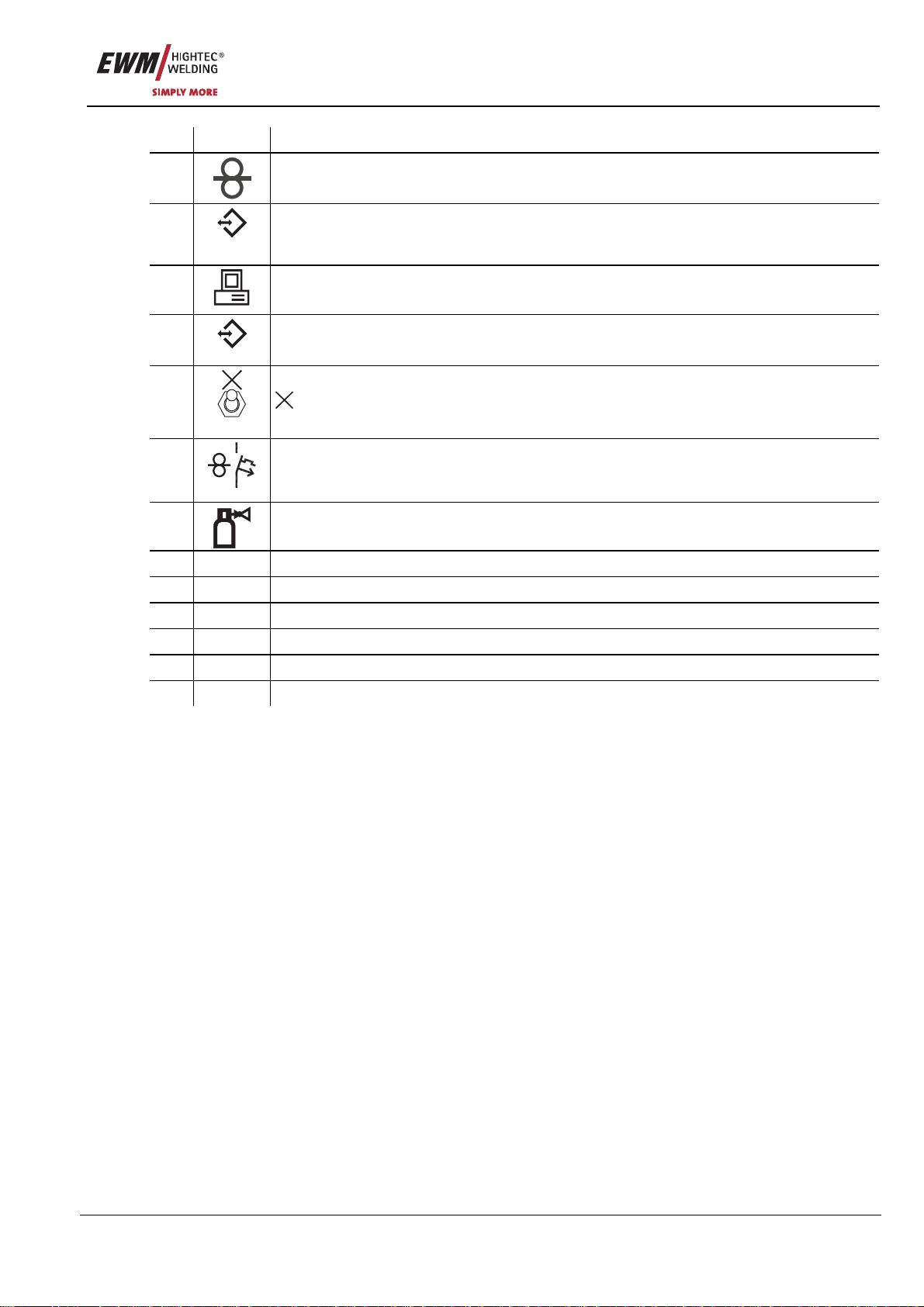
Symbol Description
Press
Do not press
Turn
Switch
01
Switch off machine
01
Switch on machine
ENTER (enter the menu)
NAVIGATION (Navigating in the menu)
EXIT (Exit the menu)
Time display (example: wait 4s/press)
Interruption in the menu display (other setting options possible)
Tool not required/do not use
Tool required/use

Safety instructions
General
Item No.: 099-000089-EWM01 9
2.2 General
DANGER
Electric shock!
Welding machines use high voltages which can result in potentially fatal electric shocks
and burns on contact. Even low voltages can cause you to get a shock and lead to
accidents.
• Do not touch any live parts in or on the machine!
• Connection cables and leads must be free of faults!
• Switching off alone is not sufficient! Wait for 2 minutes until the capacitors have discharged.
• Place welding torch and stick electrode holder on an insulated surface!
• The unit should only be opened by specialist staff after the mains plug has been unplugged!
• Only wear dry protective clothing!
Electromagnetic fields!
The power source may cause electrical or electromagnetic fields to be produced which
could affect the correct functioning of electronic equipment such as IT or CNC devices,
telecommunication lines, power cables, signal lines and pacemakers.
• Observe the maintenance instructions! (see Maintenance and Testing chapter)
• Unwind welding lines completely!
• Shield devices or equipment sensitive to radiation accordingly!
• The correct functioning of pacemakers may be affected (obtain advice from a doctor if
necessary).
Do not carry out any unauthorised repairs or modifications!
To avoid injury and equipment damage, the unit must only be repaired or modified by
specialist, skilled persons!
The warranty becomes null and void in the event of unauthorised interference.
• Appoint only skilled persons for repair work (trained service personnel)!
WARNING
Risk of accidents if these safety instructions are not observed!
Non-observance of these safety instructions is potentially fatal!
• Carefully read the safety information in this manual!
• Observe the accident prevention regulations in your country.
• Inform persons in the working area that they must observe the regulations!
Risk of injury due to radiation or heat!
Arc radiation results in injury to skin and eyes.
Contact with hot workpieces and sparks results in burns.
• Wear dry protective clothing (e.g. welding shield, gloves, etc.) according to the relevant
regulations in the country in question!
• Protect persons not involved in the work against arc beams and the risk of glare using safety
curtains!
Explosion risk!
Apparently harmless substances in closed containers may generate excessive pressure
when heated.
• Move containers with inflammable or explosive liquids away from the working area!
• Never heat explosive liquids, dusts or gases by welding or cutting!

Safety instructions
General
10 Item No.: 099-000089-EWM01
WARNING
Smoke and gases!
Smoke and gases can lead to breathing difficulties and poisoning. In addition, solvent
vapour (chlorinated hydrocarbon) may be converted into poisonous phosgene due to the
ultraviolet radiation of the arc!
• Ensure that there is sufficient fresh air!
• Keep solvent vapour away from the arc beam field!
• Wear suitable breathing apparatus if appropriate!
Fire hazard!
Flames may arise as a result of the high temperatures, stray sparks, glowing-hot parts
and hot slag produced during the welding process.
Stray welding currents can also result in flames forming!
• Check for fire hazards in the working area!
• Do not carry any easily flammable objects such as matches or lighters.
• Keep appropriate fire extinguishing equipment to hand in the working area!
• Thoroughly remove any residue of flammable substances from the workpiece before starting
welding.
• Only continue work on welded workpieces once they have cooled down.
Do not allow to come into contact with flammable material!
• Connect welding leads correctly!
CAUTION
Noise exposure!
Noise exceeding 70 dBA can cause permanent hearing damage!
• Wear suitable ear protection!
• Persons located within the working area must wear suitable ear protection!
Safety instructions
General
Item No.: 099-000089-EWM01 11
CAUTION
Obligations of the operator!
In the European Economic Area (EEA), the relevant national version of the basic
guidelines must be followed and observed!
• National version of the basic guidelines (89/391/EEC) as well as the relevant individual
guidelines.
• In particular the Directive (89/655/EEC) on the minimum regulations for safety and health
protection when staff members are using equipment during work.
• The accident prevention regulations of the relevant country (e.g. in Germany, BGV D 1).
• Check at regular intervals that users are working in a safety-conscious way!
Damage due to the use of non-genuine parts!
The manufacturer's warranty becomes void if non-genuine parts are used!
• Only use system components and options (power sources, welding torches, electrode
holders, remote controls, spare parts and replacement parts, etc.) from our range of
products!
• Only insert and lock accessory components into the relevant connection socket when the
machine is switched off.
Electromagnetic interference!
The machines are intended to be used in industrial areas, according to IEC 60974-10. If
they are used in residential areas, for example, problems may occur with ensuring
electromagnetic compatibility.
• Check whether interference is caused to other machines!

Safety instructions
Transport and installation
12 Item No.: 099-000089-EWM01
2.3 Transport and installation
WARNING
Incorrect handling of shielding gas cylinders!
Incorrect handling of shielding gas cylinders can result in serious and even fatal injury.
• Observe the instructions from the gas manufacturer and in any relevant regulations
concerning the use of compressed air!
• Place shielding gas cylinders in the holders provided for them and secure with fixing
devices.
• Avoid heating the shielding gas cylinder!
CAUTION
Risk of tipping!
There is a risk of the machine tipping over and injuring persons or being damaged itself
during movement and set up. Tilt resistance is guaranteed up to an angle of 10°
(according to IEC 60974-1, -3, -10).
• Set up and transport the machine on level, solid ground.
• Secure add-on parts using suitable equipment.
Damage due to supply lines not being disconnected!
During transport, supply lines which have not been disconnected (mains supply leads,
control leads, etc.) may cause hazards such as connected equipment tipping over and
injuring persons!
• Disconnect supply lines!
CAUTION
Equipment damage when not operated in an upright position!
The units are designed for operation in an upright position!
Operation in non-permissible positions can cause equipment damage.
• Only transport and operate in an upright position!

Safety instructions
Transport and installation
Item No.: 099-000089-EWM01 13
2.3.1 Lifting by crane
DANGER
Risk of injury during lifting by crane!
When lifting the equipment by crane, serious injuries can be inflicted by falling
equipment or add-on units.
• Transport on all lifting lugs at the same time
(see Fig. Lifting principle)!
• Ensure that there is an even load distribution! Only use ring
chains or suspension ropes of the same length!
• Observe the lifting principle (see Fig.)!
• Remove all accessory components before lifting
(e.g. shielding gas cylinders, tool boxes, wire feed units, etc.)!
• Avoid jerky movements when raising or lowering!
• Use shackles and load hooks of the appropriate size!
min. 1 m
75 °
Fig. Lifting
principle
Risk of injury due to unsuitable ring screws!
In case of improper use of ring screws or the use of unsuitable ring screws, persons can
be seriously damaged by falling equipment or add-on components!
• The ring screw must be completely screwed in!
• The ring screw must be positioned flat onto and in full contact with the supporting surfaces!
• Check that the ring screws are securely fastened before use and check for any damage
(corrosion, deformation)!
• Do not use or screw in damaged ring screws!
• Avoid lateral loading of the ring screws!

Safety instructions
Ambient conditions
14 Item No.: 099-000089-EWM01
2.4 Ambient conditions
CAUTION
Equipment damage due to dirt accumulation!
Unusually high quantities of dust, acid, corrosive gases or substances may damage the
equipment.
• Avoid high volumes of smoke, vapour, oil vapour and grinding dust!
• Avoid ambient air containing salt (sea air)!
Non-permissible ambient conditions!
Insufficient ventilation results in a reduction in performance and equipment damage.
• Observe the ambient conditions!
• Keep the cooling air inlet and outlet clear!
• Observe the minimum distance of 0.5 m from obstacles!
Installation site!
The machine must not be operated in the open air and must only be set up and operated
on a suitable, stable and level base!
• The operator must ensure that the ground is non-slip and level, and provide sufficient
lighting for the place of work.
• Safe operation of the machine must be guaranteed at all times.
2.4.1 In operation
Temperature range of the ambient air:
• -20 °C to +40 °C
Relative air humidity:
• Up to 50% at 40 °C
• Up to 90% at 20 °C
2.4.2 Transport and storage
Storage in an enclosed space, temperature range of the ambient air:
• -25 °C to +55 °C
Relative air humidity
• Up to 90% at 20 °C

Technical data
TETRIX 301-521
Item No.: 099-000089-EWM01 15
3Technical data
NOTE
Performance specifications and guarantee only in connection with original spare and
replacement parts!
3.1 TETRIX 301-521
TETRIX 301 351 421 521
Setting ranges
Welding current 5 A to 300 A 5 A to 350 A 5 A to 420 A 5 A to 520 A
Welding voltage (TIG) 10.2 to 22.0 V 10.2 to 24.0 V 10.2 to 26.8 V 10.2 to 30.8 V
Welding voltage (MMA) 20.2 to 32.0 V 20.2 to 34.0 V 20.2 to 36.8 V 20.2 to 40.8 V
Duty cycle 25 °C 40 °C 25 °C 40 °C 25 °C 40 °C 25 °C 40 °C
60%DC - 300 A - 350 A - 420 A - 520 A
80%DC 300 A - - - 420 A - 520 A -
100%DC 270 A 250 A 350 A 300 A 380 A 360 A 450 A 420 A
Load alternation 10 min. (60% DC ∧6 min. welding, 4 min. break)
Open circuit voltage 98 V 79 V
Mains voltage (tolerances) 3 x 400 V (-25 % to +20 %)
Frequency 50/60 Hz
Mains fuse (safety fuse,
slow-blow) 3 x 16 A 3 x 25 A 3 x 35 A
Mains connection lead H07RN-F4G4 H07RN-F4G6
Max. connected load
TIG 8.3 kVA 10.6 kVA 14.2 kVA 20.2 kVA
MMA 12.0 kVA 15.0 kVA 19.5 kVA 26.8 kVA
Recommended generator
rating 16.4 kVA 20.5 kVA 27.0 kVA 38.0 kVA
cosϕ0.99
Insulation class/protection
classification H/IP 23
Ambient temperature -20 °C to +40 °C
Machine/torch cooling Fan/gas or water
Cooling capacity at 1 l/min 1500 W
Max. flow rate 5 l/min
Coolant outlet pressure max. 3.5 bar
Max. tank capacity 12 l
Coolant Ex works: KF 23E (-10°C to +40°C) or
KF 37E (-20°C to +10°C)
Workpiece lead 50 mm270 mm295 mm2
Dimensions L/W/H 1100 x 455 x 950 mm
Weight 105 kg 117 kg 120 kg 128.5 kg
Constructed to standards IEC 60974-1, -2, -3, -10
/
Machine description
TETRIX 301-521
16 Item No.: 099-000089-EWM01
4Machine description
NOTE
The maximum possible machine configuration is given in the text description.
If necessary, the optional connection may need to be retrofitted (see "Accessories"
chapter).
4.1 TETRIX 301-521
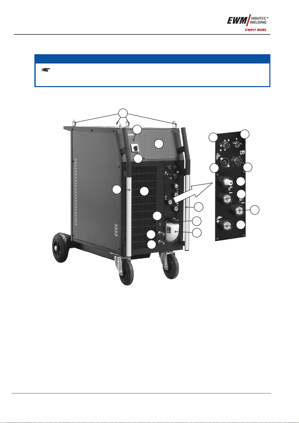
4.1.1 Front view
6
7
4
4
3
2
17
10
5
9
14
11
12
15
19
18
16
8
13
1
Figure 4-1

Machine description
TETRIX 301-521
Item No.: 099-000089-EWM01 17
Item Symbol Description 0
1 Lifting lug
2
Main switch, machine on/off
3 Machine control
See Machine control – operating elements chapter
4 Carrying handle
5 Connection socket, 8-pole / 12-pole
8-pole: TIG Up/Down or potentiometer torch control lead
12-pole: Control lead for TIG up/down torch with LED display (option)
6
0
1
Key switch for protection against unauthorised use
Position “1” > changes possible,
Position “0” > changes not possible.
Please take note of chapter “Key switch”
7
Connection socket, 5-pole
Standard TIG torch control lead
8 Connection socket, 19-pole
Remote control connection
9
G¼” connecting nipple, “-” welding current
Shielding gas connection (with yellow insulating cap) for TIG welding torch
10
Connection socket, “-” welding current
TIG welding torch connection
11
Connection socket, “-” welding current
Electrode holder connection
12
Connection socket, “+” welding current
Connection for workpiece lead
13
Automatic cut-out of coolant pump key button
press to reset a triggered fuse
14
Rapid-action closure coupling, red (coolant return)
15
Rapid-action closure coupling, blue (coolant supply)
16 Coolant tank cap
17 Coolant tank
18 Cooling air inlet
19
Operating state display
Lights up when the machine is switched on and ready for operation.
Machine description
TETRIX 301-521
18 Item No.: 099-000089-EWM01
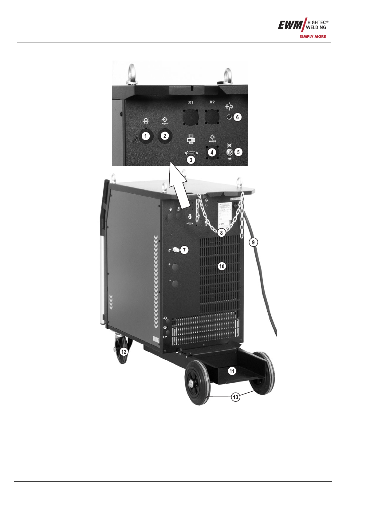
4.1.2 Rear view
Figure 4-2
Machine description
TETRIX 301-521
Item No.: 099-000089-EWM01 19
Item Symbol Description 0
1
7-pole connection socket (digital)
Wire feed unit connection
2
digital
7-pole connection socket (digital)
For connecting digital accessory components (documentation interface, robot interface
or remote control, etc.).
3
COM
PC interface, serial (D-SUB connection socket, 9-pole)
4
analog
Automation interface, 19-pole (analogue)
(see Function Specification chapter)
5
HF
HF
Ignition type changeover switch
HF
= Liftarc (contact ignition)
HF
= HF ignition
6
42V/4A
Key button, automatic cutout
Wire feed motor supply voltage fuse
(press to reset a triggered fuse)
7
G¼” connecting nipple
Shielding gas connection on the pressure reducer
8 Safety chain
9 Mains connection cable
10 Cooling air outlet
11 Cylinder bracket
12 Conveyor rolls, guide castors
13 Conveyor rolls, fixed castors

Machine description
Machine control – Operating elements
20 Item No.: 099-000089-EWM01
4.2 Machine control – Operating elements
NOTE
Machine control provides the user with up to 8 welding tasks (JOBs).
JOB 0 represents manual operating mode. This is where you can change/optimise all
parameters directly in machine control (see chapter "Operating concepts").
AMP%
AMP
sec
sec
secsec
AMP
JOB
sec
sec
sec
S
AMP
VOLT
JOB
AMP%
AMP%
T 3.24
S
COMFORT
Automatic
Puls
sec
kHz
%
kHz
3214
5
6
7
8
Figure 4-3
Item Symbol Description 0
Welding process button
MMA welding, lights up in green / arcforce setting, lights up in red
1
TIG welding
Operating mode button
spotArc (spot time setting range 0.01 sec. to 20.0 sec.)
Non-latched
2
Latched
TIG pulses key button
TIG automated pulses (frequency and balance)
3
Automatic
Puls
sec
kHz
sec
kHz
TIG pulses with times, lights up in green / Fast TIG DC pulses with
frequency and balance, lights up in red
Display changeover button
Welding current display
Welding voltage display
4
JOB number display
This manual suits for next models
3
Table of contents
Popular Welding System manuals by other brands


Magmaweld
Magmaweld ID 350 E PFC user manual

Miller
Miller Spoolmatic 30A owner's manual

Lincoln Electric
Lincoln Electric SQUARE WAVE SVM141-A Service manual

AQUARIUS
AQUARIUS 70 operating instructions

Lincoln Electric
Lincoln Electric SP-100 Service manual

FRONIUS
FRONIUS TransPocket 180 RC HW operating instructions