spotzero Sea Xchange XTC II User manual


1. INTRODUCTION ........................................................................................................................... 4
CONGRATULATIONS ................................................................................................................................................. 5
SAFETY ...................................................................................................................................................................... 5
PRINCIPLES OF REVERSE OSMOSIS....................................................................................................................... 6
UNIT SPECIFICATIONS .............................................................................................................................................. 7
2. INSTALLATION AND COMISSIONING ....................................................................................... 9
SEA XCHANGE COMMISSIONING REPORT FORM ................................................................................................ 10
ELECTRICAL REQUIREMENTS ............................................................................................................................... 12
PLUMBING AND PIPING CONNECTIONS ................................................................................................................ 12
STORAGE OR WINTERIZATION OF UNIT................................................................................................................ 13
SEA WATER PLUMBING CONNECTIONS ................................................................................................................ 17
PRE-FILTRATION ..................................................................................................................................................... 18
PRODUCT TO TANK CONNECTION ........................................................................................................................ 19
FRESH WATER FLUSH CONNECTION .................................................................................................................... 20
ELECTRICAL CONNECTIONS .................................................................................................................................. 21
3. OPERATION AND MAINTENANCE .......................................................................................... 22
XTCII CONSUMABLE ITEMS .................................................................................................................................... 23
OPERATING DO’s & DON’Ts .................................................................................................................................... 24
OPERATION SPECIFICATIONS ............................................................................................................................... 24
FEED W ATER & O P ERATIO N S P ECI FIC ATIO N S .......................................................................................... 26
ACRONYMS AND DEFINITIONS............................................................................................................................... 26
REJECTION, RECOVERY, & FLOW RATES ............................................................................................................. 27
INITIAL START- UP ................................................................................................................................................... 28
STANDARD OPERATION ......................................................................................................................................... 30
PUMP MAINTENANCE ............................................................................................................................................. 30
MEMBRANE CARE ................................................................................................................................................... 31
MEMBRANE OPERATION GUIDELINES .................................................................................................................. 31
MEMBRANE GENERAL INFORMATION ................................................................................................................... 31
MEMBRANE REMOVAL & REPLACEMENT.............................................................................................................. 32
MANUALY FLUSHING THE SYSTEM ....................................................................................................................... 34
PREPARING UNIT FOR STORAGE OR SHIPMENT ................................................................................................. 36
HIGH PRESSURE PUMP OIL CHANGE .................................................................................................................... 37
4. TROUBLESHOOTING ................................................................................................................ 38
ABNORMAL PRODUCT FLOW ................................................................................................................................. 39
DIVERSION VALVE .................................................................................................................................................. 39
TEMPERATURE CORRECTION FACTORS FOR MEMBRANE................................................................................. 40
5. XTCII TOUCH SCREEN NAVIGATION ...................................................................................... 42
HOME SCREEEN ..................................................................................................................................................... 43
STANDARD OPERATION ......................................................................................................................................... 44
MANUAL RUN PROCEDURE .................................................................................................................................... 49
MANUAL FRESH WATER FLUSH ............................................................................................................................. 52
MENU OPTIONS ....................................................................................................................................................... 52
SUMMARY ................................................................................................................................................................ 53
SYSTEM INFORMATION .......................................................................................................................................... 53
ALARMS ................................................................................................................................................................... 53
ALARM HISTORY ..................................................................................................................................................... 54
SERVICE MENU ....................................................................................................................................................... 54
SYSTEM OPTIONS ................................................................................................................................................... 54
UNITS OF MEASUREMENT...................................................................................................................................... 55
DIVERSION VALVE SETPOINT ................................................................................................................................ 55
REGULATOR VALVE ................................................................................................................................................ 56
FRESH WATER FLUSH ............................................................................................................................................ 57
TABLE OF CONTENTS
SYSTEM STANDARD OPERATING PARAMETERS.................................................................................................. 8
XTCII INSTALL KIT...................................................................................................................................................... 11
ONE LINE FLOW DRAWING........................................................................................................................................... 14
WIRING DIAGRAM................................................................................................................................................... 15
PID PLUMBING DIAGRAM....................................................................................................................................... 16

XTCII INTERNAL/FILTER COMPONENTS ................................................................................................................ 71
7. WARRANTY ................................................................................................................................. 88
6. XTCII SYSTEM SPECIFICATIONS & PARTS............................................................................ 65
PUMP/MOTOR ASSEMBLY DRAWING.................................................................................................................... 66
SALT WATER PRE-FILTER ASSEMBLY.................................................................................................................. 67
OPTIONAL SHORT PRE-FILTER ASSEMBLY DRAWING........................................................................................ 68
FRESH WATER FLUSH ASSEMBLY DRAWING...................................................................................................... 69
TOUCHSCREEN DRAWING...................................................................................................................................... 70
MODEL SELECTION WORKBOOK.......................................................................................................................... 72
HIGH PRESSURE TECHNICAL DATA..................................................................................................................... 78
BOOSTER PUMP TECHNICAL DATA...................................................................................................................... 79
3
MEMBRANE TECHNICAL DATA.............................................................................................................................. 82
BURKERT DIVERSION VALVE TECHNICAL DATA................................................................................................. 84
MAINTENANCE ........................................................................................................................................................ 58
REMOTE SUPPORT ................................................................................................................................................. 58
REMOTE TOUCH SCREEN SETUP .......................................................................................................................... 62

1. INTRODUCTION
4

CONGRATULATIONS
Your Sea Xchange XTCII-Series Reverse Osmosis System is a durable piece of
equipment that, with proper care, will last for many years. This User's Manual outlines
installation, operation, maintenance, and troubleshooting details vital to the sustained
performance of your system.
If your system is altered at the site of operation or if the feed water conditions change,
please contact your local dealer or distributor to determine the proper recovery for your
application.
NOTE: PRIOR TO OPERATING OR SERVICING THE REVERSE OSMOSIS SYSTEM,
THIS USER'S MANUAL MUST BE READ AND FULLY UNDERSTOOD. KEEP THIS AND
OTHER ASSOCIATED INFORMATION FOR FUTURE REFERENCE AND FOR NEW
OPERATORS OR QUALIFIED PERSONNEL NEAR THE SYSTEM.
SAFETY
The safety section of this User's Manual outlines the various safety headings used
throughout this manual's text and are enhanced and defined below:
NOTE: INDICATES STATEMENTS THAT PROVIDE FURTHER INFORMATION
AND CLARIFICATION .
CAUTION: INDICATES STATEMENTS THAT ARE USED TO IDENTIFY
CONDITIONS OR PRACTICES THAT COULD RESULT IN EQUIPMENT OR
OTHER PROPERTY DAMAGE.
WARNING: INDICATES STATEMENTS THAT ARE USED TO IDENTIFY
CONDITIONS OR PRACTICES THAT COULD RESULT IN INJURY OR LOSS
OF LIFE. FAILURE TO FOLLOW WARNINGS COULD RESULT IN SERIOUS
INJURY OR EVEN DEATH.
DO NOT UNDER ANY CIRCUMSTANCE; REMOVE ANY CAUTION, WARNING,
OR OTHER DESCRIPTIVE LABELS FROM THE SYSTEM.
5

PRINCIPLES OF REVERSE OSMOSIS
REVERSE OSMOSIS
How Fresh Water Is Produced
Reverse Osmosis or “RO” is a process where freshwater water is produced by pumping
saltwater through a semi-permeable membrane.
Osmosis
Osmosis is a naturally occurring process where a weak solution will cross a semipermeable
membrane to mix with a highly concentrated solution. For example, a freshwater solution will
naturally want to mix with a saltwater solution.
Reverse Osmosis
To reverse this process work is put into the system using a pump. The pump causes pressure to
build up on the saltwater side of the membrane. This pressure forces water across the semi-
permeable membrane. The membrane is designed to allow the water molecules to pass while
preventing the salt and other solids from doing so. Fresh water is collected on the other side of
the membrane as a result.
6

UNIT SPECIFICATIONS
XTCII MODEL
600
1200
1800
2200
Configuration
1 Vessel
2 Vessel
3 Vessel
4 Vessel
Feed Water Source
Sea Water
Sea Water
Sea Water
Sea Water
Rated production gpd
(gpm)
600(0.41)
1200(0.83)
1800(1.25)
2200(1.52)
Rejection and Flow Rates
Nominal Salt Rejection
%
99.4%
99.4%
99.4%
99.4%
Minimum Feed Flow
gpm (lpm)
4.2 (15.9)
4.2 (15.9)
4.2 (15.9)
4.2 (15.9)
Minimum Concentrate
Flow gpm (lpm)
3.79 (14.3)
3.3 (12.5)
2.95 (11.2)
2.68 (10.1)
Connections
Feed inch
¾” Hose
¾” Hose
¾” Hose
¾” Hose
Product inch
3/8” QC 9.5mm
3/8” QC 9.5mm
3/8” QC 9.5mm
3/8” QC 9.5mm
Concentrate inch
1/2” QC 2.7mm
1/2” QC 12.7mm
1/2” QC 12.7mm
1/2” QC 12.7mm
Membranes
Membrane Per Vessel
1
1
1
1
Membrane Quantity
1
2
3
4
Membrane Size
2540
2540
2540
2540
Pumps
High Pressure Pump
Type
Piston
Piston
Piston
Piston
HP motor amps
10.6
10.6
10.6
10.6
High Pressure Motor
HP (kw)
2.5
2.5
2.5
2.5
Booster motor amps
4.3
4.3
4.3
4.3
Booster Pump RPM @
60 (50Hz)
1750 (1450)
1750 (1450)
1750 (1450)
1750 (1450)
Electrical
Voltage
230V 50/60Hz 1Φ
230V 50/60Hz 1Φ
230V 50/60Hz 1Φ
230V 50/60Hz 1Φ
Amp Draw
14.9
14.9
14.9
14.9
System Dimensions
L x W x H inch (cm)
48.125”x18.312”x
17.625” (122.25x46
.5x44.75)
48.125”x18.312”x
17.625” (122.25x46.5
x44.75)
48.125”x18.312”x
17.625” (122.25x46
.5x44.75)
48.125”x18.312”x
17.625” (122.25x46
.5x44.75)
Weight lb. (kg)
120 (54.4)
158 (71.6)
169 (76.6)
180 (81.6)
7
Systems Standard Operating Parameters
Fresh Water RO Systems
Product
Flow
(gpm/lpm)
Concentrate
Flow
(gpm/lpm)
Recycle
Flow
(gpm/lpm)
(+/-10%)
Total Flow
(gpm/lpm)
Pump
Pressure
(psi/bar)
MAX
Concentrate
Pressure
(psi/bar)
MAX
Pre-filter Inlet
Pressure
Minimum
(psi/bar)
Pre-filter Inlet
Pressure
Maximum
(psi/bar)
Pre-filter Outlet
Pressure
Minimum
(psi/bar)
Pre-filter Outlet
Pressure
Maximum
(psi/bar)
Model/GPD
SZ/ZTCII/XZ (FW-RO) SERIES
GPD 2000
1.4/5.3
1.0/3.8
2.0/7.6
4.4/16.7
150/10.3
150/10.3
15/1
85/4
15/1
85/4
GPD 3000
2.0/7.5
1.0/3.8
2.0/7.6
5/18.9
150/10.3
150/10.3
15/1
85/4
15/1
85/4
SZ-HD/XZ-HD (FW-RO) SERIES
GPD 4000
2.7/10.2
1.5/5.7
2.0/7.6
6.2/23.5
150/10.3
150/10.3
15/1
85/4
15/1
85/4
GPD 5000
3.47/13.1
1.5/5.7
2.0/7.6
7.0/26.5
150/10.3
150/10.3
15/1
85/4
15/1
85/4
GPD 6000
4.16/15.7
2.0/7.6
2.0/7.6
8.2/31
150/10.3
150/10.3
15/1
85/4
15/1
85/4
Saltwater RO Systems
Product
Flow
(gpm/lpm)
Concentrate
Flow
(gpm/lpm)
Recycle
Flow
(gpm/lpm)
Total Flow
(gpm/lpm)
Pump
Pressure
(psi/bar)
Concentrate
Pressure
(psi/bar)
Pre-filter Inlet
Pressure
Minimum
(psi/bar)
Pre-filter Inlet
Pressure
Maximum
(psi/bar)
Pre-filter Outlet
Pressure
Minimum
(psi/bar)
Pre-filter Outlet
Pressure
Maximum
(psi/bar)
SE SERIES
GPD 350
.24/.9
2.26/8.6
N/A
2.5/9.5
N/A
850/58.6
15/1
85/4
15/1
85/4
GPD 600
.41/1.5
2.09/7.9
N/A
2.5/9.5
N/A
850/58.6
15/1
85/4
15/1
85/4
GPD 800
.55/2.0
1.95/7.4
N/A
2.5/9.5
N/A
850/58.6
15/1
85/4
15/1
85/4
GPD 1200
.83/3.1
1.67/6.3
N/A
2.5/9.5
N/A
850/58.6
15/1
85/4
15/1
85/4
SX/XTCII/XZ (SW-RO) SERIES
GPD 600
.41/1.5
3.79/14.3
N/A
4.2/15.9
N/A
850/58.6
15/1
85/4
15/1
85/4
GPD 1200
.83/3.1
3.37/12.8
N/A
4.2/15.9
N/A
850/58.6
15/1
85/4
15/1
85/4
GPD 1800
1.25/4.7
2.95/11.2
N/A
4.2/15.9
N/A
850/58.6
15/1
85/4
15/1
85/4
GPD 2200
1.52/5.75
2.68/10.1
N/A
4.2/15.9
N/A
850/58.6
15/1
85/4
15/1
85/4
SXII-HD/XZ-HD (SW-RO) SERIES
GPD 3600
2.5/9.46
5/18.9
N/A
7.5/28.4
N/A
850/58.6
15/1
85/4
15/1
85/4
GPD 4300
2.98/11.28
7.5/28.4
N/A
10.5/39.7
N/A
850/58.6
15/1
85/4
15/1
85/4
GPD 5000
3.47/13.13
7.0/26.5
N/A
10.5/39.7
N/A
850/58.6
15/1
85/4
15/1
85/4
CX SERIES
GPD 20000
13.88/52.54
46/174
N/A
60/227
N/A
850/58.6
15/1
85/4
15/1
85/4
Standard Parameters
Total Dissolved Solids for Fresh Water Systems (PPM)
Product Water Side
90% less than feed water
Total Dissolved Solids for Sea Water Systems (PPM)
Product Water Side
Less than 500 PPM
Temperature (F/C)
77/25
8

2. INSTALLATION AND COMISSIONING
9

SEA XCHANGE COMMISSIONING REPORT FORM
System Information:
Model number -
Date of Commission -
Installed by -
Serial number -
Commissioned by-
Vessel hull number-
First step to commissioning a new system is to look over the install to be sure everything is installed correct. This check-
list must be gone through prior to powering up the system.
Have all plumbing connections have been made, and secured?
Have all plumbing lines been run to the correct locations?
Is the boost pump installed below the water line?
Has wire reinforced hose been used on the suction side of the boost pump?
Is raw water intake open?
Is the overboard open and free of obstructions?
Is the system voltage, hertz, and phase correct?
Is the circuit breaker sized properly with sufficient wire gauge?
Is the power cable connected to the power inlet terminals of the system?
Now power up the system,
Are all displays on and functional?
At this time follow the start-up procedure in the manual and operate the system for an hour at its rated capacity, then
record the following data.
System operating readings
Pre-filter inlet Pre-filter outlet psi
Concentrate pressure
psi
psi
gpm
Product flow gpm Product TDS ppm
Feed water TDS ppm Feed water temperature F or C
Hours on system hrs Amp draw Voltage
Location system was tested
Problems or other notes:
Concentrate flow
10

XTCII INSTALL KIT
✓
PART NUMBER
DESCRIPTION
QTY
B0001
Elbow 1/4" QC
4
B0005
Tee 3/8" QC
2
B0006
Tee 1/2" QC
2
B0019
Adapter 1/2" QC to 1/2" MNPT
2
B0020
Elbow 1/2" QC
4
B0021
Elbow 3/8" QC
4
B0024
Reducer 1/2" QC Stem to 3/8" QC
2
B0030
Adapter 3/8" QC to 1/2" MNPT
2
B0033
Reducer 1/2" QC to 3/8" MNPT
2
B0043
Valve Ball 3/8" QC
1
B0048
RELEASE TOOL SET
1
B0052
Adapter 1/2" QC Stem to 15mm QC
1
B0053
Adapter 3/8" QC Stem to 15mm QC Stem
1
B0054
Elbow 15mm QC
1
B0055
Elbow 15mm QC Stem to 15mm QC
1
B0058
Adapter 5/8" QC Stem to 3/8" QC
2
B0059
Adapter 1/2" CTS Stem to 3/8" CTS
2
B1040
Elbow 3/4" MNPT to 3/4" HB Nylon
2
B1041
Adapter 3/4" MNPT Nylon
1
B5000
Locking Clip, 1/4", Install Kit 20pc
1
B5001
Locking Clip, 3/8", Install Kit 20pc
1
B5002
Locking Clip, 1/2", Install Kit 20pc
1
E1018
Wrench for Big Clear 4.5" #10 & #20
1
H5065
Lubricant Silicone 6 grams
1
H5089
Install Kit 5/16" Hardware Set
1
H5095
Install Kit - Hose clamp and end cap
1
J0001
Hose, 3/4" White
50 ft.
J0003
Tubing, Nylon, 0.375 in. OD
50 ft.
J0004
Tubing, Nylon, 0.50 in. OD
50 ft.
MN 2003
XTCII Manual
1
P4010
GP - Oil 16Oz
1
11

ELECTRICAL REQUIREMENTS
ELECTRICAL The XTCII Series are available in 1Φ (phase).
230 volts at 14.9 amps (including booster pump)
50/60 Hertz available in the 230-volt unit
NOTE: IT’S RECOMMENDED THAT A QUALIFIED ELECTRICIAN WIRE YOUR SYSTEM IN
ACCORDANCE WITH ALL APPLICABLE CODES, RULES, AND REGULATIONS.
WARNING: TO REDUCE THE RISK OF ELECTRICAL SHOCK, THE INCOMING
POWER SUPPLY MUST INCLUDE A PROTECTIVE GROUND.
PLUMBING AND PIPING CONNECTIONS
PLUMBING
The membranes and high-pressure pumps used on XTCII-Series Reverse Osmosis Systems re-
quire a continuous flow of water with a maximum temperature not to exceed 113°F. Please see
Complete Install Guide and the connection drawings below.
CAUTION: ANY RESTRICTIONS OR BLOCKAGE IN THE CONCENTRATE LINE CAN
CAUSE BACKPRESSURE, WHICH WILL INCREASE THE SYSTEM’S OPERATING
PRESSURE. THIS CAN RESULT IN DAMAGE TO THE SYSTEM’S MEMBRANES AND
COMPONENTS.
TUBE CUTTING AND INSTALLATION PROCEDURE
Cut the tube square and remove burrs and sharp
edges. Ensure the outside diameter is free of score
marks. For soft or thin walled tube, we recommend
the use of a tube insert.
Push the tube into the fitting, to the tube stop.
To disconnect, ensure the system is depressurized,
push the collet square against the fitting. With the
collet held in this position the tube can be removed.
12

STORAGE OR WINTERIZATION OF UNIT
Option 1: Storage with Fresh Water Flush
When a system will not be used for a significant period of time (i.e. 3 months – 1
year), the best practice for storage of the system is to allow the automatic fresh
water flush to operate by leaving the power to the system on and ensuring that the
vessels fresh water system is ON and pressurized. Normal replacement of fresh
water flush filter is still required every 4 months.
Option 2: Storage without Fresh Water Flush:
If the vessel will not be able to allow for fresh water flushing over the duration of
the storage period, the membrane vessels must have static water replaced with
membrane storage chemical solution. Membrane storage chemical part # is
252404263.
Option 3: Winterization
Option 3a: Winterization with membrane rack removal - The best practice for
winterization is to remove membrane rack and store with membrane storage
chemical in heated storage climate. The remainder of the system should be stored
with propylene glycol from sea cock to overboard to prevent freeze damage
(propylene glycol can be purchased at most hardware or automotive retailers).
Option 3b: Winterization without membrane rack removal - If the system is
going to be exposed to freezing or near freezing temperature while being stored
and the membrane rack cannot be removed and stored in a heated climate, the
following should be done. A 50% solution of storage chemical and 50% propylene
glycol should be run through the entire system from sea cock to overboard and
then valve off both sea cock and overboard. Membrane storage chemical part # is
252404263.
NOTE: PROPYLENE GLYCOL CAN BE PURCHASED AT MOST HARDWARE OR
AUTOMOTIVE RETAILERS
WARNING: DO NOT USE ETHYLENE GLYCOL, ONLY NON-TOXIC
PROPYLENE GLYCOL SHOULD BE USED.
Re-commissioning of System after Storage or Winterization
After storage or winterization, the system must be completely voided of all storage
chemical and or propylene glycol. To do this, follow the new system startup guide
on page 28.
13
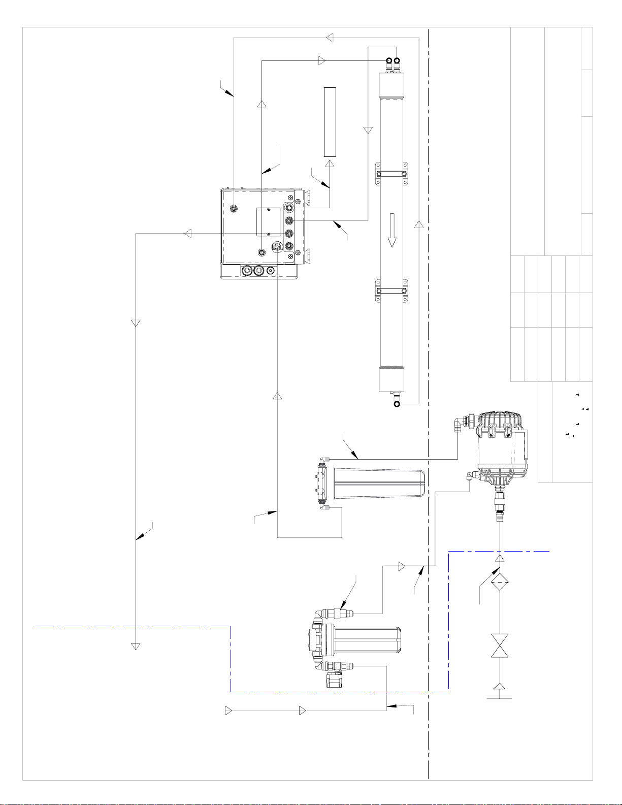
Feed From
Pre-Filtration
Membrane
Supply
3/8" OD
3/4" ID
1/2" OD
1/2" OD
Product
to Tank
3/4" ID
Fresh Water
Flush Cartridge
(P/N 252404295)
Check
Valve
Boost
Pump
Note:
1) 3/4" supply hose for Boost Pump must be wire reinforced.
2) Clamshell water inlet recommended before sea cock.
3) Boost Pump must be installed below water line.
SEA
XCHANGE
SHIP
SUPPLIED
Pre-Filter
(P/N 252404298)
From Ships
Pressurized Fresh
Water Supply
Water Line
Sea Water
Intake
Sea
Cock
Sea
Strainer
To Ships
Freshwater Tank
Overboard
Membrane
Product SW
Membrane
Return
1/2" OD
3/8" OD
3/8" OD
3/8" OD
OR GREATER
3/4" ID
(Must be wire
reinforced hose)
REVISIONS
REV.
DESCRIPTION
NAME
DATE
APPROVED
D
SHIP TO SEA EXCHANGE DIVIDING LINE ADDED, DOBULE FILTERS REPLACED WITH SINGLE
DOUBLE STACK FILTER, AND BACTERIOSTATIC REMINERALIZER REMOVED
JD
7/29/2020
SHEET 1 OF 1
1/29/20
ES
UNLESS OTHERWISE SPECIFIED:
SCALE: 1:10
DWG. NO. PD0001
NAME
DATE
Q.A.
MFG APPR.
ENG APPR.
CHECKED
DRAWN
DIMENSIONS ARE IN INCHES
TOLERANCES:
.015
FRACTIONAL
1/32
ANGULAR: MACH
1/2 BEND
1
TWO PLACE DECIMAL
.010
THREE PLACE DECIMAL
.005
PROPRIETARY AND CONFIDENTIAL
THE INFORMATION CONTAINED IN THIS DRAWING IS THE SOLE PROPERTY OF SPOT ZERO. ANY
REPRODUCTION IN PART OR AS A WHOLE WITHOUT THE WRITTEN PERMISSION OF SPOT ZERO IS
PROHIBITED.
XTCII One Line Flow Drawing
DWG. REV E
14

Optional
Ship's Tank
Level Sensor
(TL)
EGND
EGND
L2
BP
L1
L2
HP
L2
TDS
TL
PO/PP
CP
PF
PI/RF
CF
N2K
FWSW
DSPL
FWF/IS
CV
PV
DV
BPR
XTC II
YEL
WHT
GRY
GRN
BLK
RED
SHIELD
WHT
BLK
RED
BLK
RED
BRN
RED
BLK
WHT
RED
BLU
WHT
RED
BLK
WHT
BLK
RED
BLK
WHT
RED
GRN
WHT
GRN
BLK
RED
BLK
RED
BLK
RED
BLK
RED
BLK
RED
WHT
BLK
EGND
EGND
L2
BP
L1
L2
HP
L2
FWSW
ZTC II
WHT
BLK
RED
B(-)
A(+)
GND
GND
+24VDC
B(-)
A(+)
GND
GND
+24VDC
System Enclosure
NEMA2K Bus
(Optional)
ZTCII System
(Optional)
GND
L2
L1
Inlet Power
Supply
L2
L2
L2
L1
L1
L1
GND
GND
GND
Touch Panel
Optional Remote Touch Panel
Product
TDS
Pre-Filter Outlet
Pressure
(PO/PP)
Concentrate
Pressure
(CP)
Product
Flow
Pre-Filter Inlet
Pressure
(Optional)
FWF Valve
(FWF/IS)
Cooling Fan
(CV)
Cooling Fan
(PV)
Backpressure
Regulator
Valve
(BPR)
Diversion Valve
(DV)
High Pressure
Pump
Booster Pump
REVISIONS
REV.
DESCRIPTION
DATE
APPROVED
C
SYSTEM ENCLOSURE EXTENDED TO INCLUDE HIGH PRESSURE PUMP
6/10/2021
SHEET 1 OF 1
1/27/2020
ES
UNLESS OTHERWISE SPECIFIED:
SCALE: NTS
DWG. NO. ED1003
NAME
DATE
Q.A.
MFG APPR.
ENG APPR.
CHECKED
DRAWN
DIMENSIONS ARE IN INCHES
TOLERANCES:
.015
FRACTIONAL
1/32
ANGULAR: MACH
1/2 BEND
1
TWO PLACE DECIMAL
.010
THREE PLACE DECIMAL
.005
PROPRIETARY AND CONFIDENTIAL
THE INFORMATION CONTAINED IN THIS DRAWING IS THE SOLE PROPERTY OF SPOT ZERO. ANY
REPRODUCTION IN PART OR AS A WHOLE WITHOUT THE WRITTEN PERMISSION OF SPOT ZERO IS
PROHIBITED.
XTCII Wiring Diagram
DWG. REV C
15

SEA WATER PLUMBING CONNECTIONS
1. Locate a dedicated sea cock to be used for booster pump supply. Sea cock should be a
minimum of 3/4” with a speed scoop to prevent a Venturi effect while vessel is underway.
2. Install a sea strainer with at least a 50-mesh rating after sea cock.
3. Install supplied booster pump below water line.
Note - Booster pump outlet must remain the highest point of pump and cannot be rotated 90°
4. Run reinforced suction hose from sea cock to sea strainer to booster pump in an upward flow
manner to prevent air traps.
5.
6. Use supplied white 3/4” flexible hose from discharge of booster pump to Pre-Filter Inlet
connection on Sea Xchange Sediment filter assembly located on left side of system. Filter
assembly may be remote mounted if desired.
17

¾” Flexible hose
from Booster Pump
PRE-FILTRATION
XTCII-Series systems are supplied with a 5-
micron sediment filter. Change when there is a
noticeable loss of outlet pressure. Ask your local
dealer or distributor about Pre-Filtration
systems, if required.
NOTE: THE SYSTEM MUST BE OPERATED IN
ACCORDANCE TO FEED WATER SPECIFICATIONS.
7. Double clamp all sea water hose connections to prevent potential leaks.
8. Locate connection labeled “Overboard” on lower left side of system. Run supplied white 1/2”
tube to a dedicated overboard connection.
Warning - Sea water overboard must never
be closed or obstructed while system is
operational. Closing or obstructing the
overboard flow on system may cause
permanent damage to system.
1/2” Tube out to
dedicated Overboard
18

PRODUCT TO TANK CONNECTION
9. Locate the fitting labeled Product to Tank on left side of system. Connect supplied white 3/8”
tubing from system to the inlet of the ships freshwater tank. Be sure that there are no kinks in hose
run and avoid 90’s where possible to prevent restricted flow.
Warning - Ships freshwater tank must be vented properly to avoid back pressure on
system. Failure to do so may cause permanent damage to system and/or to not
function properly.
Warning - Product to tank must never be closed or obstructed while system is
operational. Closing or obstructing the product flow on system may cause permanent
damage to system and/or to not function properly.
Ship’s Fresh Water
Tank
3/8” tubing to ship’s
fresh water tank.
19

FRESH WATER FLUSH CONNECTION
1. Locate filter assembly labeled Fresh Water Flush and connect the inlet of fresh water flush
solenoid to the ships pressurized freshwater system.
Note - a shut off valve is recommended to be installed on supply line to fresh flush assembly for
service.
2. Run supplied white 3/8” tubing from outlet filter assembly labeled Fresh Water Flush
Ship’s Fresh
Water Tank
20

ELECTRICAL CONNECTIONS
1. Connect main power supply to main power terminal blocks, connect power to booster pump from
contactor as shown below. Ground main power supply and booster pump to grounding bus bar.
Reference DWG SX0034.
•
The XTCII-Series systems pump, and motor are available in 230 Volt, 50/60 Hertz, 1 Phase
•
Ensure that the electrical circuit supplying the system is compatible with the requirements of
the specific XTCII model you are installing.
NOTE: IT’S RECOMMENDED THAT A QUALIFIED ELECTRICIAN WIRE YOUR SYSTEM IN
ACCORDANCE WITH ABYC REQUIREMENTS.
WARNING: TO REDUCE THE RISK OF ELECTRICAL SHOCK, THE INCOMING
POWER SUPPLY MUST INCLUDE A PROTECTIVE GROUND.
PC BOARD DIP SWITCH SETTINGS
21
This manual suits for next models
4
Table of contents


