Springer BC-127 User manual
It includes guarantee certificate
Incluye certificado de garantia
Nota: las instruciones en Español empiezan en la página 18
For future reference, fill in detail of your purchase belo and keep this O ne's Guide in a safe place.
Conserve el manual para futuras referencias.
BC -R/D
Leer el manual antes de usar.
Read the owner`s guide before using.
Owner's Guide
Owner's Guide
Manual del Usuario e Instalacion
Manual del Usuario e Instalación

2

3
Congratulations!
CONTENTS
- Important recommendations............................................................................................ 3
- Installation instructions ................................................................................................... 4
- Electrical installation ...................................................................................................... 7
- Power suply ..................................................................................................................... 9
- Operating your air conditioning unit ................................................................................ 11
- Care and maintenance of t e appliance .......................................................................... 16
- Troubles ooting Guide ................................................................................................... 17
IMPORTANT RECOMMENDATIONS
- install your air conditioning unit facing t e longest side of t e c osen
room.
- t e ideal installation eig t is 1.5 m up from t e floor level.
- in t e event of installing a second air conditioning unit in t e same
room, avoid t e proximity of t e two appliances.
- NEVER install your device be ind curtains, furniture or dividers, be-
cause t is may block t e air flow of your appliance.
LIST OF SYMBOLS
- Ground
- Caution
- Risk of electric disc arge
- Fuse
- Read t e manual before using.
V - Volt
A - Amps
Hz - Hertz
W - Watt
Kg - Kilogram
Oz - Ounce
in - in
IPXX - IP number
You made t e perfect c oice. You just acquired a world class
tec nology product. Custumed in ig resistance plastic for a
longer lasting, lig ter and more compact appliance. W ic also
avoids rusting problems.
In t is andbook, we will try to clarify all your doubts,
from t e installation premises election to t e basic andle con-
trols.

4
- Its better to install your appliance on t e walls facing east or sout ,
w ere solar incidence is weaker.
- avoid using t e cooling function of your appliance wit indoors tem-
peratures lower t an 20OC, so ice may not be formed on t e internal
eat exc anger.
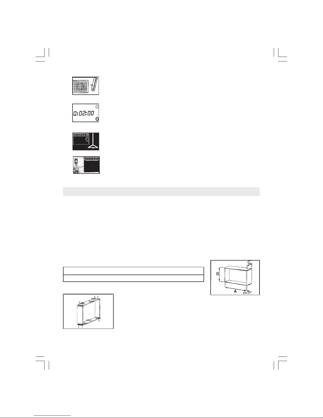
A B C (máx.)
Dimensions 60,5 cm 38,5 cm 17,0 cm
INSTALLATION INSTRUCTIONS
INSTALLATION ON WALLS
T e opening in t e wall must allow t e perfect fit of a framework to fix t e appliance,
as well as to give a decorative finis ing. Remember t at t e wooden beams of t e framework
must be of at least of 2.5 cm t ick.
You must ave in mind t at t e wall you c oose to install t e unit on must be free of
pillars, girders, pipelines and electrical ducts. According to t e following table and t e previous
figure, c ose t e internal sizes of t e framework:
- To avoid freezing of t e external eat exc anger, do not use t e eating
function wit outdoors temperatures lower t an 4OC.
- WHENEVER you want to c ange from t e cooling function to t e warm-
ing function, or conversely, turn off t e equipment and wait at least 2
minutes before turning it on again.
- If electrical energy is interrupted, immediately turn your unit off and
turn it on again just after 1 minute of t e energy re-establis ment. T is
procedure will avoid damage to t e compressor due to tension varia-
tions.
- Do not use t e temperature control (t ermostat knob) as a switc to
turn on-off t e equipment. T e t ermostat is t e principal safety device
of its electrical circuit.

5
Build t e framework, fixing t e four parts. Put and fix t e frame
onto t e wall t roug 6 fixing points (3 upside and 3 downside).
INSTALLATION OF THE APPLIANCE
- to detac t e metallic base of t e appliance, unscrew t e
safety screw located on t e rig t and side lateral part of t e same.
- join t e two lateral beams to t e base wit a screw in eac
lateral.
- fix t e metallic set (base and beams) to t e framework,
wit t ree screws at t e base and two screws at eac lateral beam.
NOTE: before resuming t e installation, be sure t at t e
slope of t e base is 0.5 blister (1 cm).
- slide t e appliance on t e metallic base all t e way and
put t e safety screw located in t e straig t lateral part of t e
appliance back on.
- arrange t e restraining foam to t e lateral and upper parts
between t e framework and t e appliance to avoid air flow between
t e external and t e internal environments.
- fix t e molding on t e wall to finis t e installation
procedure.
IMPORTANT
1) Once t e installation ended, confirm t e slope of t e appliance is correct.
2) To reduce t e cable lengt :
- wit draw t e plastic front..
- adjust t e cable lengt , arrange t e remaining cable on
screw

6
t e back of t e control panel.
- Put t e plastic front back on by encasing first t e lower
part and t en t e upper part.
3) T e unit comes out of factory wit t e cable arranged on
rig t and side, but if you wis , it is possible to c ange it to t e
ot er side. To do t is, wit draw t e plastic front, pass t e cable to
t e ot er side placing it in t e lower part of t e appliance, and clip
t e plastic front on t e labeled place.
4) Your appliance as a drainage for water to exit. Depending
on t e place of installation, you may use a ose connected to t e
drainage net of your residence to avoid water dripping from
occurring.
5) In order to keep a normal air flow t roug t e compressor
and condenser please verify t at t e lateral and superior openings
of t e appliance are turn outward and TOTALL cleared.
Ot erwise, your appliance may present operation problems, wit
possible compressor failure. Very t ick walls s ould be beveled
outwardly.
WALL INSTALLATION USING SPECIAL CONCRETE BOXES
- follow all t e previous instructions.
- verify if t e slope of t e appliance is correct (0,5 blister - 1 cm).
- leave lateral and upper openings so t e air flow wit in t e
compressor and t e condenser is normal.
INSTALLATION ON WINDOWS
T e installation on windows is recommended only in t ose
cases in w ic t ere is not any possibility of installing t e appliance
Drain

7
on walls, since it can cause vibrations and noise. But, if it is t e
only place available, follow t ese suggestions:
- You must ave an iron or steel reinforced structure, Frenc
and type or loafer, duly measured for your appliance, similar
dimensions to t ose for wall installation.
- Avoid all contact of t e appliance wit t e glass panes,
supporting it wit rubber cradles to avoid vibrations and noise.
ELECTRICAL INSTALLATION
1. All t e wiring will ave to comply wit t e local and national codes of electricity and
it will ave to be installed by qualified personnel.
2. T ere must be available an individual derived circuit wit a proper outlet for t e
exclusive operation of t is air conditioning appliance. Consult following table wit information
on t e capacity suggested for t e cables for t e derived circuit.
3. It is essential t at t e outlet plug t at you select matc es t e inlet plug of t e
appliance and it is wit in reac ing distance of t e installed appliance.
NOTE: The inlet cord is 39 inches (991 mm) long and it is at-
tached to the lower part of the command checkerboard. DO NOT
SE a plug adapter nor an extension cord. Check Table 2 for in-
formation on types of plugs and fuses.
4. Comply wit t e fuse type (Table 2) indicated in t e data plate of t e appliance,
located above t e air disc arge.
5. IMPORTANT : T e wires in t e principal cable are arranged according to t e following
colour code:
Green and Yellow: Eart Blue: Neutral Brown: P ase
Since t e colors of t e wires in t e principal cable of t is equipment could not
correspond to t e terminals identifying colours in t e plug, proceed in t e following way:
t e green and yellow wire must be connected to t e terminal in t e plug t at it is labeled
wit t e letter E (Eart ) or by t e eart symbol or coloured green and yellow.
t e blue wire must be connected to t e terminal t at it is labeled wit t e letter N or black
coloured.

8
* NOMINAL CONDITIONS:
TEMPERATURE CLIMATE
220 V - 1 PHASE - 50 HZ
ISO 5151.2/T1
indoor: 27OC dry bulb 19OC wet bulb
outdoor: 35OC dry bulb 24OC wet bulb
** MAX. CONDITIONS:
198V - 1 PHASE 50 HZ
ISO 5151.2/T1
indoor: 32OC dry bulb 23OC wet bulb
outdoor: 43OC dry bulb 24OC wet bulb
*** NOMINAL CONDITIONS:
220 V - 1 PHASE - 50 HZ
AHAM RAC-1
indoor: 21,1OC dry bulb 15OC wet bulb
outdoor: 8,3OC dry bulb 6,1OC wet bulb
**** MAX. CONDITIONS:
198V - 1 PHASE - 50HZ
ISO 5151-2
indoor: 27OC
outdoor: 24OC dry bulb 18OC wet bulb
t e brown wire must be connected to t e terminal t at it is labeled wit t e letter L or
coloured in red.
MODELS
POWER SUPPLY
OPERATING
ELETRIC DRAWS
LOCKED ROTOR CURRENT (NOTE 1)
MAIN
SUPPLY DELAYED FUSES
WIRE SIZE (NOTE 2)
OPERATING
LIMITS
POWER SUPPLY
COOLING
HEATING
MAXIMUM
TEMP.
MINIMUM
TEMP.
NOMINAL
CONDITIONS *
MAX.
CONDITIONS **
NOMINAL
CONDITIONS *
MAX.
CONDITIONS **
OUTSIDE
ROOM
OUTSIDE
ROOM
mm2
A
oC
V
A
W
A
W
A
W
A
W
A
oC
oC
oC
220 V
1 PHASE - 50 HZ
22,8
6,0
1340
N/A
15
2,5
43
32 d. b.
23 w. b.
19
21 d. b.
15 w. b.
198 in - 264 ax.
__
BC-127-
cooling only
N/A
19
__
43
32 d. b.
23 w. b.
21 d. b.
15 w. b.
9
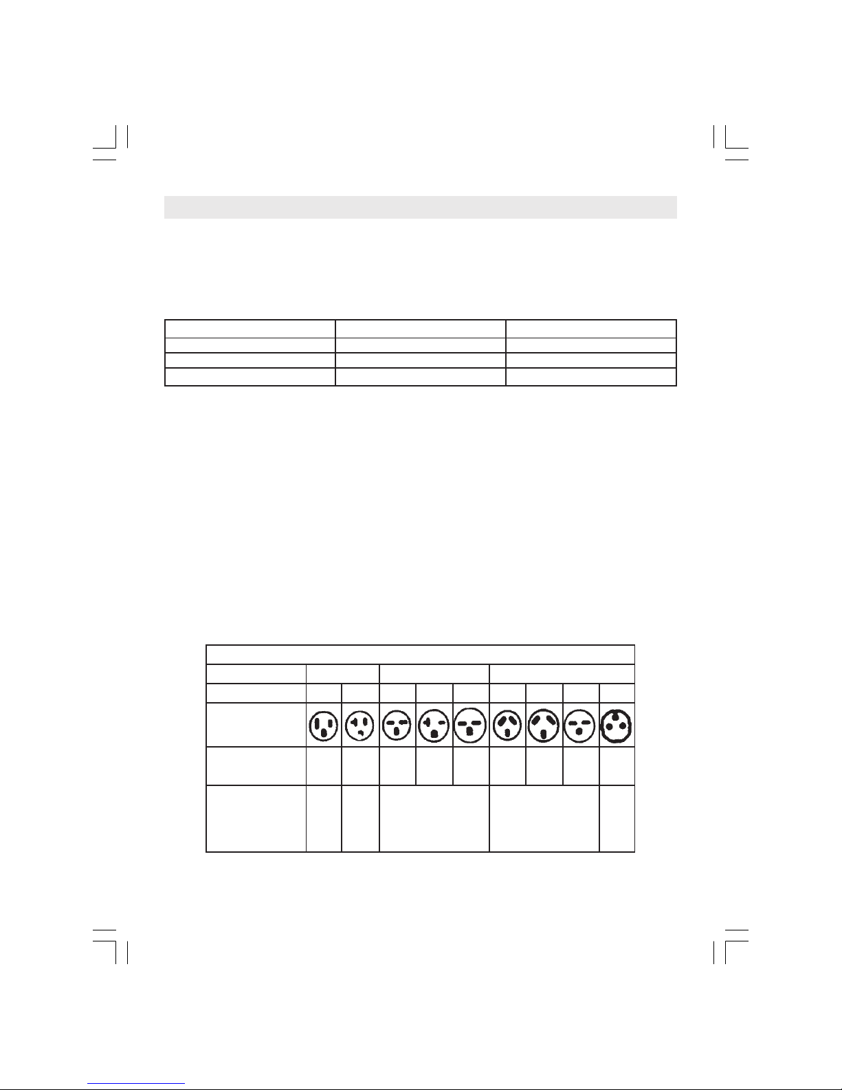
RECEPTACLE AND FUSE TYPES
RATED VOLTS
AMPS
125
15 20
250
15 20 30
250
10 20 30 16
WALL
OUTLET
FUSE
SIZE 15 20 15 20 30 15 20 30 15
TIME DELAY
FUSE
(or Circuit
Breaker)
Plug Plug Cartridge Used on
Argentina only
used
on
Europe
TABLE 2
Cable (mm2) Max. Amps (A) Recommended Fuse (A)
1,5 13 16
2,5 18 20
4,0 24 25
Values taken from t e standard for cables in conduits.
IMPORTANT:
T e conductors current capacity s all NEVER be less t an t e t ermomagnetic circuit
breaker capacity.
It is not recommended to install two single-p ase t ermomagnetic circuit breakers in
t is case.
Before plug in t e equipment, c eck if t e outlet polarity is t e same as t e one s own
in t e equipment data s eet.
POWER SUPPLY
Always use t ermomagnetic circuit breakers toget er wit differential circuit breakers.
T e wiring s all comply according wit t e Standards for buildings. T e nominal section of t e
power supply line conductors for t e electric outlet s all comply wit t e directives of standards
considering t e nominal current, t e total lengt until t e power consumption point and t e
correction factors for cabling grouping s all be verified.

10
GROUNDING
All our units are manufactured according to t e strictest safety requirements. To ensure a
complete and effective protection to t e user IT IS VERY IMPORTANT AND ESSENTIAL TO
HAVE A PERFECT GROUNDING CONNECTION.
Comply wit t e standards about t e grounding connections for t is type of equipment, even
if t e circuit as a differential circuit breaker for its additional protection.
Use grounding conductors similar to t e power supply cables wit green or yellow insulation
colors.
IN NONE CIRCUNSTANCES t e unit’s plug s all be removed by cutting t e power supply
cables, or a two-pin plug installed, and adapters s all not be used for plugging t e unit. Use
t ree-pin plugs only.
NEVER connect t e grounding cables to water distribution pipes. T is action may cause a
risk for you as well as for ot er people.
THE UNIT SHALL BE PLUGGED IN ONL AFTER OU HAVE COMPLIED WITH ALL THESE
REQUIREMENTS.
11
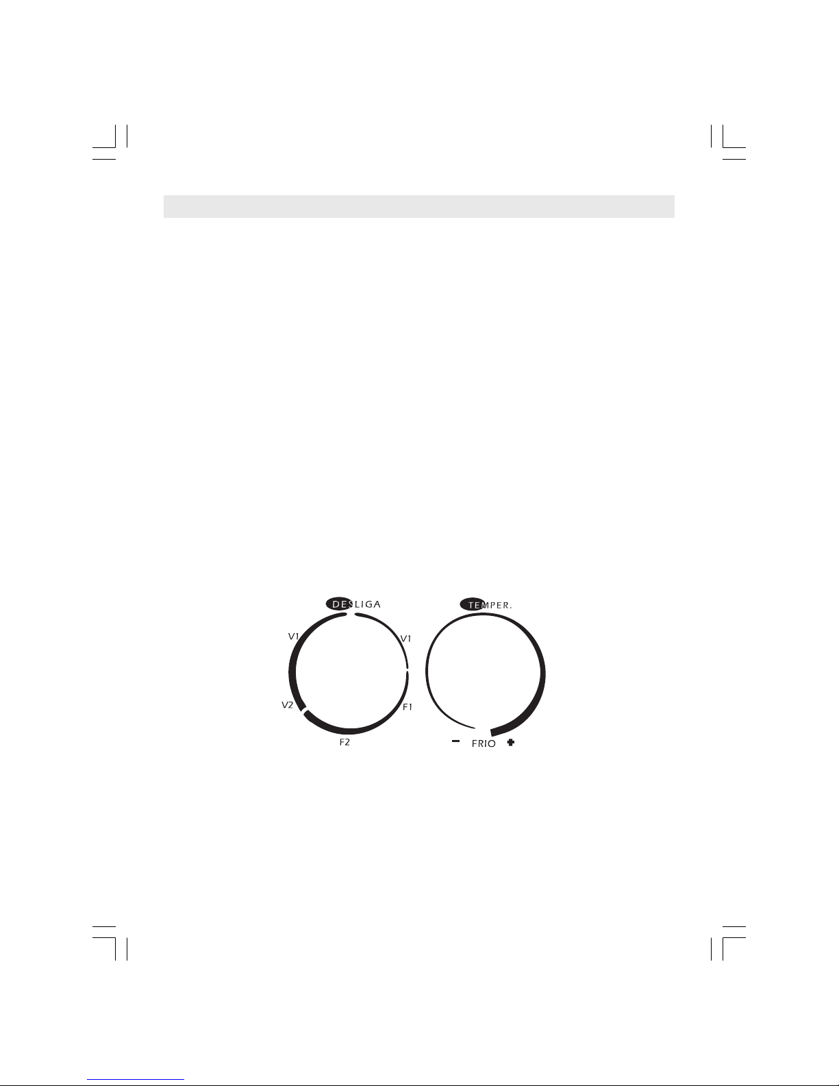
OPERATING YOUR AIR CONDITIONING APPLIANCE (FOR MECHANICAL UNITS ONLY)
In order to get t e best performance of your air conditioning unit is necessary for you
to know ow to operate t e t ermostat and t e select functions knobs properly.
Reading t e following instructions you will understand easily ow to operate your
equipment.
- always turn t e select functions knob clockwise.
- turn t e knob until desired position is reac ed-cooling (FRIO) or fan (V).
- turn t e t ermostat knob to t e maximum position for t e c osen function.
- wait for t e equipment to work raising or dropping room temperature.
- once you feel comfortable wit t e temperature reac ed turn slowly t e t ermo-
stat knob in t e opposite sense, towards t e minimum position, until a click is
eard.
- t en turn t e knob in t e opposite sense, towards t e maximum position, just a
little.
By following t e previously described procedure you will be setting t e equipment to
maintain t e current temperature w ic you find ideally comfortable.
To turn off your air conditioning appliance its enoug to turn t e select function knob
clockwise to t e OFF (DESLIGA) position.
12
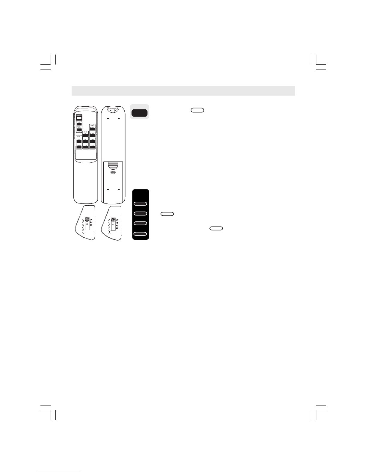
OPERATINGYOURAIRCONDITIONINGAPPLIANCE(FORREMOTECONTROLUNITSONLY)
By pressing t e key you turn your ELECTRONIC AIR
CONDITIONING ON or OFF on t e remote control. W en
you turn on t e equipment, t e LEDs on t e electronic panel will
display t e information from t e previous programming. W en you
turn it off, all LEDs turn off as well. W en you c ange any setting
on your remote control, t e electronic panel on t e inside unit will
acknowledge t e c ange wit a "BEEP". Don't worry if you try to
turn on t e equipment again in less t an 3 minutes and it does not
respond immediately, as t is is normal procedure controlled by an
internal safety device on t e compressor.
By pressing t e FUNCTION keys you can select t e de-
sired OPERATION MODE.
On (HEAT)mode t e equipment will raise t e selected
temperature between 18 and 29 ºC. W en switc ing t e
OPERATION MODE to (HEAT) t e electronic control-
ler will assume t e last selected temperature. If t is is not
t e lowers
LIGA/DES
AQUEC.
AQUEC.
REFRIG.
VENT.
AUTO
FUNÇÃO
LIGA/DES
AQUEC.
13
TEMP.
+
-
TEMP.
On (COOL) mode t e equipment will lower t e selected
temperature between 18 (64F) and 29 ºC (84F). W en switc ing
t e OPERATION MODE to , (COOL) t e electronic controller
will assume t e last selected temperature. If t is is not t e conve-
nient temperature, you can c ange t e settings by using t e
or keys. T e activation of t is mode will be acknowledged
by an orange LED on t e electronic panel.
On (FAN) mode, t e equipment circulates t e air by using
t e fan only, wit no temperature c ange. T e activation of t is
mode will be acknowledged by a green LED on t e electronic panel.
T e mode keeps t e temperature constant as monitored by
t e electronic controller, automatically switc ing between COOL-
ING and HEATING and alsoc anging t e speed as necessary. W en
switc ing to t e electronic controller will assume t e last
selected temperature. If t is is not t e convenient temperature,
you can c ange t e settings by using t e or
keys.
Once t e electronic controller as selected an operation mode, it
won't be c anged in less t an 30 minutes since t e last mode
switc , even if it is necessary, in order to protect t e equipment.
T e option is only available on units t at operate bot on
cooling and eating.
T e activation of t is mode will be acknowledged simultaneously
by an orange LED and a red LED on t e electronic panel.
By pressing t e TEMP keys, you perform t e ppropriate
TEMPERATURE SETTING for your convenience.
T e key raises t e temperature. T e key
REFRIG.
TEMP.
+TEMP.
_
AUTO
TEMP.
+TEMP.
_
AUTO
AUTO
VENT.
TEMP.
+
_
TEMP.
REFRIG.

14
T is option can be viewed on sis LEDs on t e electronic
panel, as s own on t e table on t e rig t:
Note:
• on (FAN) mode, t e temperature LEDs will remain
off.
• t e electronic panel will "BEEP" twice if t e tempera-
ture range is exceeded.
By pressing t e SPEED keys, you select t e desired
FAN SPEED.
: HIGH: by pressing t is key, your air conditioner
will operate at top fan speed, regardless of temperature
mode.
: LOW: by pressing t is key, you air conditioner
will operate at minimun fan speed, regardless of tempera-
ture mode.
By pressing t e "TIMER" keys you can set t e unit's operation
time until it is automatically turned off. You can c oose between:
: 2 - by pressing t is key once, you set t e equipment to
turn off after two ours.
: 5 - by pressing t is key once, you set t e equipment to
turn off after five ours.
: 8 - by pressing t is key once, you set t e equipment to
turn off after eig t ours.
T ese settings will be acknowledged by a yellow LED on t e elec-
tronic panel.
To c ange t e equipment's operation time, just press t e key for
t e newly desired selection. Just bear in mind t at, by performing
t is c ange, you will be canceling t e previous setting and starting
a new one, and t e newly selected time will be counted from t e
moment of c ange.
To cancel a program setting, just press t e same key t at was
used to activate it. T e canceling of t e "TIMER" mode will be ac-
knowledged by t e turning off of t e yellow LED on t e electronic
panel.
ALTA
BAIXA
2h
5h
8h
!!
!!
!
TEMP. 18ºC 19ºC 20ºC 21ºC 22ºC 23ºC 24ºC 25ºC 26ºC 27ºC. 28ºC 29ºC
ALTA
BAIXA
VELOC.
2 h
5 h
8 h
TIMER
VENT.
15
BASIC PROCEDURE
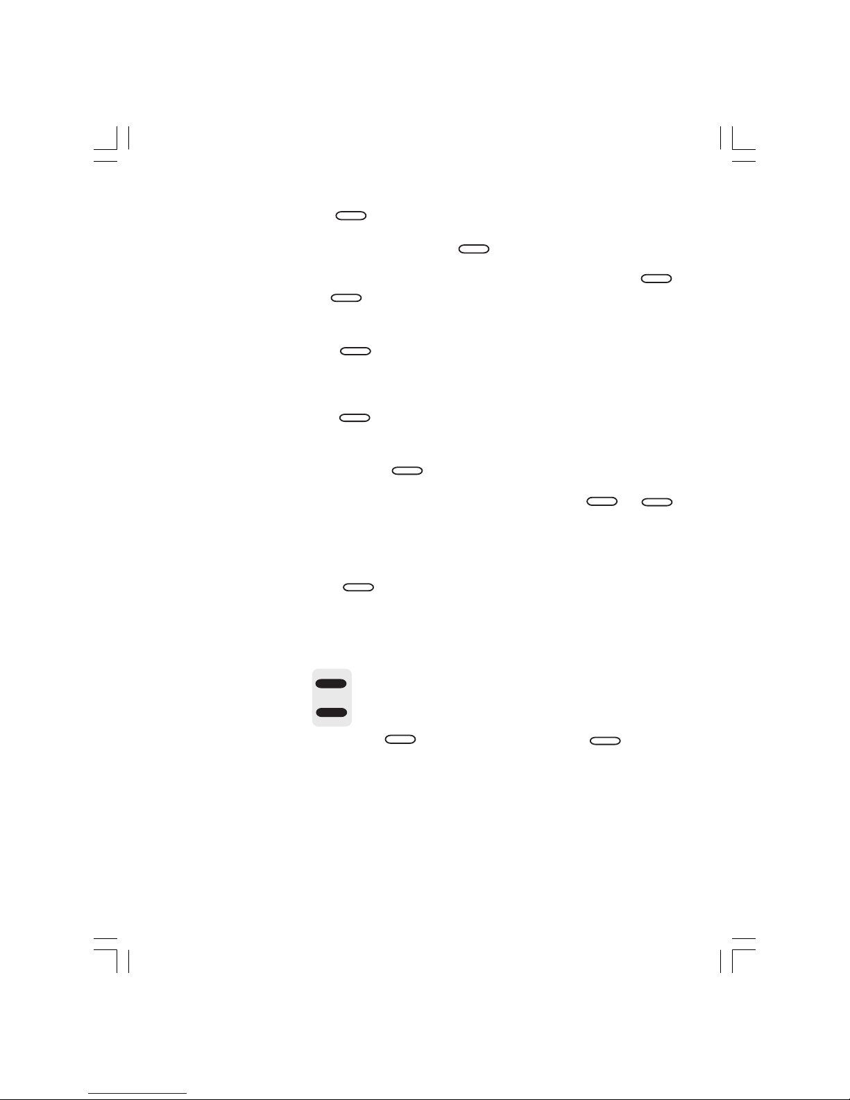
REPLACING THE REMOTE CONTROL BATTERIES
T e remote control of you ELECTRONIC AIR CONDITIONING
uses two AA 1,5 V batteries. Never use old batteries or any type
ot er t an t e specified one and keep in mind t at t e average lasting
time of a battery is 1 (one) year. Do not replace batteries w ile t e
equipment is on. Remove t e cover of t e battery c amber on t e
upper part of t e remote control and replace t em. Test t em by
turning off t e equipment. If it doesn't work, remove t e batteries and
repeat t e operation.
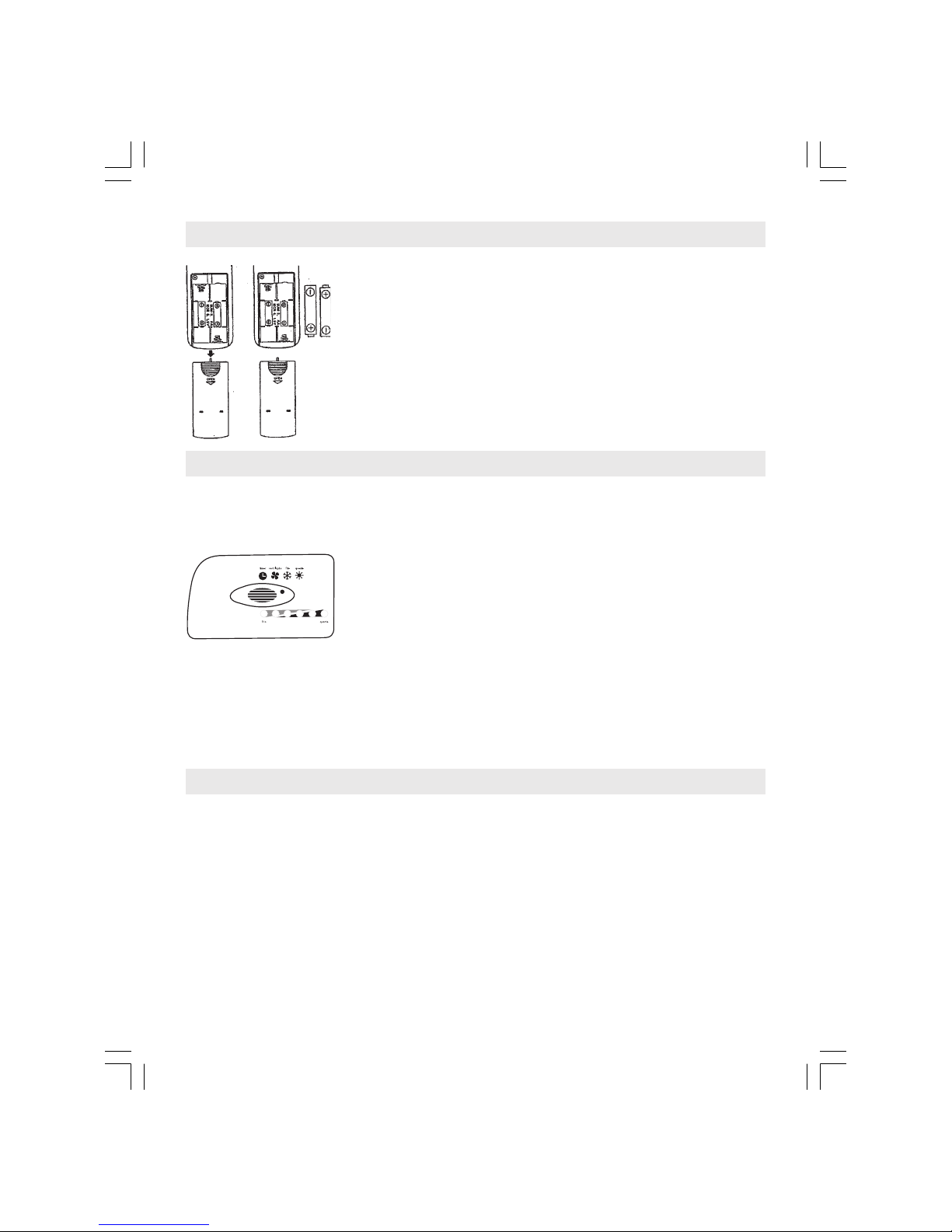
EMERGENCY MODE
T is mode s ould only be used to activate t e equipment in case of dead batteries on
t e remote control or loss or damage of t e remote control.
T e EMERGENCY MODE is activated by an inside button
on t e electronic panel, as s own on t e left. Use a pointed object
to activate t e button.
By pressing t e button once, t e equipment will operate on:
COOLING: on cooling-only units.
AUTO: on units t at operate bot on cooling eating.
On bot cases, t e equipment will assume 23OC (73F) as t e convenient tempera-
ture. By pressing t e button once again, t e equipment will turn off.
REMOTE CONTROL POSITIONING
• T e remote control can be used at a maximum distance of 7 meters from t e
equipment.
• Getting sounds:
T e "BEEP" will be eard in t e following cases, indicating t at a command was
accepted:
- on turning on
- on turning off
- on switc ing modes
- on c anging t e temperature setting

16
DIRECTING THE AIR FLOW
You can c ange t e direction to w ic t e air flows by moving t e adjustable baffles
on your unit. You can move t em up, down, to t e left or to t e rig t.
CARE AND MAINTENANCE OF THE APPLIANCE
Clean t e plastic front and t e cabinet wit a damp flannel or a soft clot wit
warm water and neutral soap. Do not use steel sponges on t e appliance because t ey
may scratc t e surface. NEVER use detergents, alco ol or water directly on t e plastic
front of t e appliance.
AIR FILTER
Your air conditioning appliance as a filter t at retains all t e impurities of t e air.
T e filter requires special care, to clean it follow de instructions:
- before to start cleaning it, turn off it t e appliance.
- to remove it, raise it using t e two andles located under t e air ex aust of your
appliance.
- vacuum clean or was it wit luke warm water and neutral soap. Flap and let dry
well before putting it back on t e appliance.
- clean t e filter every two weeks.
IMPORTANT
- a dirty air filter means a reduced capacity of your air conditioning unit
and an energy consumption increase.
-NEVER operate your appliance wit out t e air filter, since t e dust and
ot er solid particles may penetrate t e components, and t us damag-
ing your appliance.
- for t e models wit eaters, it is advisable to turn on t e eating once
a mont .
- if t e device is not going to be used in long time, turn off t e main
switc and unplug it.
CABLES
Verify periodically if t e power supply cable or register are damaged, for safety do not use t e
unit. Before using t e equipment again t e power supply cable must be replaced by qualified
personnel, manufacturer or specialized tec nical service.

17
TROUBLESHOOTING GUIDE
Before calling a tec nician, see ow to proceed if your air conditioning device presents
some of t e following described symptoms.
TROUBLE PROBABLE CAUSE SOLUTIONS
The unit does not work 1) The main switch turned off 1) Turn main switch back on
2) Appliance is unplugged 2) Plug your unit to the electrical
outlet
3) Energy failure 3) Wait for the energy to come back
The unit does not 1) irty air filter 1) Clean the air filter
work properly 2) Air flow is blocked 2) Remove objects interfering
the air flow (curtains, furniture, ...)
3) The room is not well closed 3) Be sure all the doors and
windows are well closed
4) There is some heat source 4) Supress any heat source
5) Thermostat knob is not 5) Place the thermostat knob
correctly placed correctly according to this
handbook
6) The device is under 6) Chose a larger model to fulfill
dimensioned for the premises your needs
Frozen internal 1) Unproper air flow 1) Move objects that may be
heat exchanger blocking the air flow
2) irty air filter 2) Clean the air filter
Water leaks within 1) Clogged drainage 1) Unclogged the drainage
the room 2) Improper installation 2) Install the unit properly according
to this handbook

18
¡Felicitaciones!
Usted acaba de acer una excelente elección. Usted adquirió
un producto con tecnología mundial, producido en plástico de
alta resistencia que permite más durabilidad, elimina problemas
de oxidación y ace con que el aparato sea más liviano y
compacto.
En este manual, procuramos aclarar todas sus dudas, desde
el lugar elegido para la instalación asta el simple manejo de
los controles
RECOMENDACIONES IMPORTANTES
- instale su aire acondicionado de frente para el una mayor dimensión
del ambiente escogido.
- la altura ideal para la instalación es de 1,5m arriba del nivel del piso.
- en la instalación de un segundo aire acondicionado en un mismo
ambiente, evite la proximidad de los dos aparatos.
- JAMÁS obstruya la circulación de aire de su aparato, instalándolo
atrás de cortinas, muebles o poneles divisorios.
LA LISTA DE SÍMBOLOS
- Tierra
- Precaución
- Riesgo de c oque eléctrico
- Fusible
- Leer el manual antes de usar.
V - Volt
A - Ampere
Hz - Hertz
W - Watt
Kg - Kilogramo
Oz - Onza
in - Pulgada
IPXX - Número IP
ÍNDICE
- Recomendaciones importantes ..................................................................................... 18
- Instrucciones para instalación ....................................................................................... 19
- Instalación eléctrica ...................................................................................................... 22
- Alimentación elétrica ..................................................................................................... 24
- Operando su aparato de aire acondicionado .................................................................. 26
- Conservación y mantenimiento del aparato ................................................................... 31
- Soluciones prácticas..................................................................................................... 32
19
- evite el uso de este aparato en la operación calentamiento con
temperaturas externas inferiores a 4OC, pues podrá ocurrir el
congelamiento del dispositivo de calor externo.
-SIEMPRE que quiera cambiar de la operación enfriamiento para
calentamiento, o viceversa, apague el equipo y aguarde 2 minutos
antes de encenderlo nuevamente.
-si la energía eléctrica fue interrumpida, apague inmediatamente su
aire acondicionado y solamente vuelva a encenderlo 1 minuto
después del restablecimiento. Ese procedimiento evitará variaciones
de tensión que pueden ocasionar que el compresor se queme.
-no utilice el interruptor como llave de encendido-apagado del equipo.
El interruptor es el principal dispositivo de seguridad de su circuito
eléctrico.
INSTRUCCIONES PARA INSTALACIÓN
INSTALACIÓN EN PAREDES
La abertura en la pared debe permitir el encaje perfecto de un marco para fines de
acabado, bien como para fijar el aparato. Conviene recordar que el espesor de la madera
del marco debe ser de por lo menos de 2,5 cm.
Usted debe tener muc a atención cuando escoja el local en la pared. Él debe estar
libre de pilares, vigas, tuberías y electroductos. De acuerdo con la tabla a seguir y la figura
anterior, vea los tamaños internos del marco:
A B C (máx.)
Tamaño 60,5 cm 38,5 cm 17,0 cm
Arme el marco, fijando las cuatro partes. Coloque y fíjelo en la
pared a través de los 6 puntos de fijación (3 arriba y 3 abajo).

20
INSTALACIÓN DEL APARATO
- para desprender la base metálica del aparato, retire el
tornillo de seguridad localizado en la parte lateral derec a del
mismo.
- prenda los dos tirantes laterales en la base con un tornillo
en cada lateral.
- fije el conjunto metálico (base y tirantes) en el marco,
prendiéndolo y fijándolo con los tres tornillos de la parte inferior y
los dos laterales.
NOTA: antes de continuar la instalación, observe si la
inclinación de la base es de 0,5 ampolla (1 cm).
- deslice el aparato sobre la base metálica asta el fondo y
coloque el tornillo de seguridad localizado en la parte lateral
derec a del aparato.
- coloque la espuma de vedado en las laterales y parte
superior entre el marco y el aparato para evitar el pasaje de aire
del ambiente externo para el interno y viceversa.
- fije la moldura en la pared para dar el acabado en la
instalación.
IMPORTANTE
1) Terminada la instalación, observe si la inclinación del aparato está correcta.
2) Para disminuir la largura del cable:
- retire la frente plástica a través de los dos tornillos localizados en la parte superior
del aparato.
- ajuste el tamaño del cable, colocando la parte excedente atrás del panel de
control.
- Coloque nuevamente la frente plástica encajando primero la parte inferior de la
misma.
3) El cable de su aparato sale de fábrica colocado al lado derec o, pero si usted lo
desea, es posible cambiarlo de lado. Para esto, retire la frente plástica, pase el cable para el
otro lado acomodándolo en la parte inferior del aparato, recorte la frente plástica en el local
marcado.
traba mo dura
Torni o de
seguridad inc inación
torni o
torni o
Table of contents
Languages:
Popular Air Conditioner manuals by other brands


Airwell
Airwell Electra JMF Hi wall Series Service manual

Daikin
Daikin FFQ25B9V1B Operation manual

TemperZone
TemperZone OSA 840RKTB installation guide

Tecumseh
Tecumseh TC300 SERIES Operator's manual

air choice
air choice TY-EA-03 user manual

Mitsubishi Electric
Mitsubishi Electric MSC-GE20VB operating instructions


