Square QED-2 Training manual

Power-Style™
QED-2 Switchboards /
Tableros de distribución tipo autosoportado QED-2 /
Panneaux de commutation QED-2
Instruction Bulletin / Boletín de instrucciones /
Directives d’utilisation
80043-055-13
03/2018
Retain for future use. / Conservar para uso futuro. / À conserver pour usage ultérieur.


Power-Style™
QED-2 Switchboards
Class 2700
Instruction Bulletin
80043-055-13
03/2018
Retain for future use.
ENGLISH

ENGLISH
Hazard Categories and Special Symbols
Read these instructions carefully and look at the equipment to become familiar with
the device before trying to install, operate, service, or maintain it. The following
special messages may appear throughout this bulletin or on the equipment to warn
of hazards or to call attention to information that clarifies or simplifies a procedure.
The addition of either symbol to a “Danger” or “Warning” safety label indicates that
an electrical hazard exists which will result in personal injury if the instructions are
not followed.
This is the safety alert symbol. It is used to alert you to personal injury hazards.
Obey all safety messages that follow this symbol to avoid possible injury or death.
NOTE: Provides additional information to clarify or simplify a procedure.
Please Note
Electrical equipment should be installed, operated, serviced, and maintained only
by qualified personnel. No responsibility is assumed by Schneider Electric for any
consequences arising out of the use of this material.
A qualified person is one who has skills and knowledge related to the construction,
installation, and operation of electrical equipment and has received safety training
to recognize and avoid the hazards involved.
DANGER
DANGER indicates a hazardous situation which, if not avoided, will result in
death or serious injury.
WARNING
WARNING indicates a hazardous situation which, if not avoided, could result in
death or serious injury.
CAUTION
CAUTION indicates a hazardous situation which, if not avoided, could result in
minor or moderate injury.
NOTIC
E
NOTICE is used to address practices not related to physical injury. The safety
alert symbol is not used with this signal word.

ENGLISH
Table of Contents Power-Style™ QED-2 Switchboards
3© 1988–2018 Schneider Electric All Rights Reserved80043-055-13
Table of Contents
Section 1—Introduction .......................................................................................... 7
Inspection and Packaging ................................................................................ 7
Document Replacement .................................................................................. 7
Section 2—Safety Precautions .............................................................................. 8
Section 3—Receiving, Handling, and Storing ........................................................ 9
Receiving ......................................................................................................... 9
Handling ........................................................................................................... 9
Handling with Lifting Straps ....................................................................... 9
Handling without Lifting Straps ................................................................ 11
Storing ............................................................................................................ 13
Section 4—Installation ......................................................................................... 14
Location ......................................................................................................... 14
Foundation Preparation ................................................................................. 14
Switchboard Preparation ................................................................................ 15
General Installation ........................................................................................ 15
Joining Shipping Sections—Outdoor Switchboards ....................................... 16
Joining Shipping Sections—Indoor Switchboards ......................................... 17
Anchoring for Seismic Qualifications ............................................................. 18
Responsibility for Mitigation of Seismic Damage..................................... 18
Maintaining Seismic Certification............................................................. 18
Anchoring QED-2 Equipment for Seismic Applications ........................... 19
Base Anchoring ....................................................................................... 20
Top Anchoring/Restraint .......................................................................... 22
Anchoring the Switchboard ............................................................................ 24
Through Bus Splice Connections ................................................................... 24
Ground Bus Splice Connections .................................................................... 25
Grounding and Bonding ................................................................................. 26
Service Equipment—Grounded System .................................................. 26
Service Equipment—Ungrounded System .............................................. 28
Not Service Equipment ............................................................................ 28
High-Impedance Grounded Neutral Systems .......................................... 28
Busway Connections ..................................................................................... 28
Busway Connection—NEMA Type 1 (Indoor) Only (Qwik Flange™) ...... 28
Busway Connections—NEMA Type 1 (Non-Qwik Flange) and
NEMA Type 3R........................................................................................ 30
Conduit Area .................................................................................................. 31
Cable Pulling .................................................................................................. 32
Cable Terminations ........................................................................................ 32
Cable Restraint for Short-Circuit Current Rating (SCCR) .............................. 33
Section 5—Pre-energizing Checkout Procedure ................................................. 36
Ground Fault Protection Systems .................................................................. 38
Section 6—Energizing the Switchboard ............................................................... 39
Section 7—Maintaining the Switchboard ............................................................. 40
General Inspection and Cleaning ................................................................... 40
Bus Bar Joints, Lug Terminations, and Insulating Materials .......................... 41
General Lubrication Information ..................................................................... 41
Automatic Transfer Switches ......................................................................... 41
Bolt-Loc Bolted Pressure Contact Switch Maintenance (800–4,000 A) ......... 42

Power-Style™ QED-2 Switchboards Table of Contents
4
ENGLISH
© 1988–2018 Schneider Electric All Rights Reserved 80043-055-13
Circuit Breakers ............................................................................................. 43
QMB/QMJ/QMQB1 Fusible Switches ............................................................ 45
Switch Maintenance................................................................................. 45
Fuse Replacement (Fusible Switches Only) ............................................ 45
Installing QMB/QMJ/QMQB1 Fusible Switches ....................................... 46
Removing QMB/QMJ/QMQB1 Fusible Switches ..................................... 47
Ground Fault Protection Systems .................................................................. 47
Section 8—Adverse Circumstances ..................................................................... 48
Inspection Following a Short Circuit ............................................................... 48
Clean-up Following a Short Circuit ................................................................ 48
Water-Soaked Switchboards ......................................................................... 48
Water-Sprayed or Splashed Switchboards (Clean Water Only) .................... 49
Inspection and Clean-up of Clean Water Sprayed or
Splashed Switchboards ........................................................................... 49
Section 9—Torque Values for Electrical Connections ......................................... 51
Section 10—Switchboard Insulation Resistance Chart ........................................ 53
Section 11—Reference Publications .................................................................... 54
Section 12—Installation and Maintenance Log .................................................... 55

List of Figures Power-Style™ QED-2 Switchboards
5
ENGLISH
© 1988–2018 Schneider Electric All Rights Reserved80043-055-13
List of Figures
Figure 1 – Typical QED-2 Roof Hood Construction ............................................. 7
Figure 2 – Lifting with an Overhead Crane, Lifting Straps, and Cables or Chains .... 9
Figure 3 – Handling Instruction Label, Switchboards without Lifting Straps ...... 11
Figure 4 – Rear Warning Label, Rainproof Switchboards .................................. 12
Figure 5 – Front Warning Label, Rainproof Switchboards ................................. 12
Figure 8 – Belleville Washer .............................................................................. 19
Figure 9 – Base Channel Floor Anchor Bolt Locations ...................................... 21
Figure 10 – Base Channel Mounting Hardware ................................................... 22
Figure 11 – Top Anchor Hard-Point Locations ..................................................... 23
Figure 12 – Top Anchor Mounting Hardware ....................................................... 23
Figure 13 – Switchboard Base Channels ............................................................. 24
Figure 14 – Proper Orientation of U-shaped Splice Connector ........................... 25
Figure 15 – Ground Bus Splice Connection ......................................................... 25
Figure 16 – Series 2 Ground Bus Splice Connection .......................................... 25
Figure 17 – Grounding Electrode Connector ....................................................... 26
Figure 18 – Main Bonding Jumper ....................................................................... 27
Figure 19 – Series 2 Main Bonding Jumper ......................................................... 27
Figure 20 – Qwik Flange Installation .................................................................... 29
Figure 21 – Qwik Flange ...................................................................................... 29
Figure 22 – Removing the Busway Dummy Flanged End ................................... 30
Figure 23 – Flanged-End Connections ................................................................ 30
Figure 24 – Reinstalling the 1/2-In. (13 mm) Hardware ....................................... 31
Figure 25 – Cable Restraint Example .................................................................. 33
Figure 26 – Wrapping Cables (neutral cables not shown) ................................... 34
Figure 27 – Wrapping the Space Between Cables .............................................. 34
Figure 28 – Finish Wrapping the Space Between Cables ................................... 35
Figure 30 – Type BP Bolt-Loc Fusible Switch ...................................................... 42
Figure 31 – PowerPact™ R-Frame Circuit Breaker ............................................. 43

Power-Style™ QED-2 Switchboards List of Tables
6
ENGLISH
© 1988–2018 Schneider Electric All Rights Reserved 80043-055-13
List of Tables
Table 1 – Enclosure X,Y, Z Dimensions in Inches (mm) .................................. 20
Table 2 – Cable Restraint Criteria .................................................................... 33
Table 3 – I-Line™ Blank Fillers and Extensions ............................................... 44
Table 4 – QMB/QMJ Fusible Switch Blank Fillers ............................................ 46
Table 5 – QMQB1 Fusible Switch Blank Fillers ................................................ 46
Table 6 – Incoming, Branch, and Neutral Lug .................................................. 51
Table 7 – Multiple Conductor Neutral and/or Ground Bar ................................ 51

Section 1—Introduction Power-Style™ QED-2 Switchboards
7© 1988–2018 Schneider Electric All Rights Reserved80043-055-13
ENGLISH
Section 1—Introduction
This manual contains instructions for the proper installation, operation, and
maintenance of Power-Style™ QED-2 switchboard equipment manufactured by
Schneider Electric. Engineering, installation, and operating staff supervisors should
familiarize themselves with this manual and become acquainted with the
appearance and characteristics of each piece of equipment mounted or contained
in the switchboard.
These instructions and procedures apply to Power-Style QED-2 switchboard
installations by Schneider Electric. When special features or non-standard
components are incorporated in the switchboard, detailed instructions for these
components are included in the instruction material holder.
NOTES:
Series 2: There are references to Series 2 switchboards in several places in
this instruction bulletin. To determine if the QED-2 switchboard is a Series 2
model, check the rating nameplate located on the front cover. If the
switchboard is a Series 2 model, the nameplate indicates that. If it is not a
Series 2 model, there is not a Series designation.
QED-2 with Vented Roofs: Some QED-2 designs are roof vented, with an
option for roof hoods in lieu of drip pans. If roof hoods are selected, they are
shipped separately and will be installed on top of the vented roof using four (4)
self-threading, 0.25 in. (6 mm) fasteners (included). They require 6 in.
(152 mm) of additional height clearance. See Figure 1 for typical roof hood
construction.
Inspection and Packaging
Every Power-Style QED-2 switchboard is carefully inspected and packaged at the
assembly plant. Construction of the switchboard is checked, both structurally and
electrically, for compliance with all specifications, codes, and standards. After a
complete inspection, the switchboard is prepared for shipment. Each section is
shipped separately for easier handling before installation. The factory order
number, an identification number, and the shipping weights are plainly marked on
each shipping section.
Document Replacement
Contact your local Schneider Electric representative to replace lost or damaged
wiring diagrams and instruction sheets. Use the factory order number as a reference.
Figure 1 – Typical QED-2 Roof Hood Construction

Power-Style™ QED-2 Switchboards Section 2—Safety Precautions
8© 1988–2018 Schneider Electric All Rights Reserved 80043-055-13
ENGLISH
Section 2—Safety Precautions
DANGER
HAZARD OF ELECTRIC SHOCK, EXPLOSION, OR ARC FLASH
• Apply appropriate personal protective equipment (PPE) and follow safe
electrical work practices. See NFPA 70E or CSA Z462.
• This equipment must be installed and serviced only by qualified personnel.
• Perform such work only after reading and understanding all of the instructions
contained in this bulletin.
• Turn off all power supplying this equipment before working on or
inside equipment.
• Before performing visual inspections, tests, or maintenance on this equipment,
disconnect all sources of electric power. Assume all circuits are live until they
are de-energized, tested, and tagged. Pay particular attention to the design of
the power system. Consider all sources of power, including the possibility of
backfeeding.
• Always use a properly rated voltage sensing device to confirm power is off.
• Practice lock-out/tag-out procedures according to OSHA requirements.
• Handle this equipment carefully and install, operate, and maintain it correctly
in order for it to function properly. Neglecting fundamental installation and
maintenance requirements may lead to personal injury, as well as damage to
equipment or other property.
• Carefully inspect your work area and remove any tools and objects left inside
the equipment.
• Replace all devices, doors, and covers before turning on power to
this equipment.
• All instructions in this manual assume that the customer has taken these
measures before performing maintenance or testing.
Failure to follow these instructions will result in death or serious injury.
WARNING
POTENTIAL COMPROMISE OF SYSTEM AVAILABILITY, INTEGRITY, AND
CONFIDENTIALITY
• Change default passwords to help prevent unauthorized access to device
settings and information.
• Disable unused ports/services and default accounts, where possible, to
minimize pathways for malicious attacks.
• Place networked devices behind multiple layers of cyber defenses (such as
firewalls, network segmentation, and network intrusion detection and
protection).
• Use cybersecurity best practices (for example: least privilege, separation of
duties) to help prevent unauthorized exposure, loss, modification of data and
logs, interruption of services, or unintended operation.
Failure to follow these instructions can result in death, serious injury, or
equipment damage.

Section 3—Receiving, Handling, and Storing Power-Style™ QED-2 Switchboards
9© 1988–2018 Schneider Electric All Rights Reserved80043-055-13
ENGLISH
Section 3—Receiving, Handling, and Storing
Receiving
Upon receipt, check the packing list against the equipment received to ensure the
order and shipment are complete. Also upon receipt, immediately inspect
switchboard sections for any damage that occurred in transit. If damage is found or
suspected, file a claim with the carrier immediately and notify the nearest
Schneider Electric representative.
Handling
Ensure that proper equipment, such as an overhead crane, is available at the
installation site to handle the switchboard. This equipment helps avoid injury to
personnel and damage to the switchboard.
The shipping weight of each shipping section is marked on the packing list. Verify
the lifting capacity of the equipment being used to handle the switchboard in
accordance with the shipping weight of each shipping section. Keep the
switchboard upright during handling.
Schneider Electric recommends using an overhead crane, lifting straps, and cables
or chains to handle the switchboard. This method and alternative handling methods
are discussed in this section.
Handling with Lifting Straps Schneider Electric provides lifting straps as standard equipment for NEMA Type 1
switchboard shipping sections rated 3,000 A or less. Instruction labels on each
shipping section include drawings and written instructions outlining the proper use
of the lifting straps (Figure 2). Use rigid spreaders or a spanner bar to provide
vertical lift on the lifting straps. This helps avoid damage to the frame or finish.
WARNING
SPECIAL HANDLING REQUIREMENTS
• Do not lay the equipment on its front or sides.
• Lay equipment only on its back when special handling is required.
• Do not ship the equipment lying down.
Failure to follow these instructions can result in serious injury or equipment
damage.
Figure 2 – Lifting with an Overhead Crane, Lifting Straps, and Cables or
Chains
Spreader beam
Front View Side View
Lifting straps
45° min. angle

Power-Style™ QED-2 Switchboards Section 3—Receiving, Handling, and Storing
10 © 1988–2018 Schneider Electric All Rights Reserved 80043-055-13
ENGLISH
Follow these instructions to handle the switchboard:
1. Use load-rated cables or chains with safety hooks or shackles. Do not pass
cables or chains through holes in lifting straps.
2. Use a load-rated spreader beam to prevent structure damage. Rig so that the
minimum angle between the lifting cables or chains and equipment top is
45 degrees.
Follow these instructions for laying equipment on its back:
1. Remove shipping skid and equipment back covers.
2. Use overhead cranes, lifting straps, and cables or chains for laying equipment
on its back.
3. Rate of drop or pickup for laying equipment on its back is four feet per minute
or less.
4. Reverse the procedure to stand the equipment in its upright position.
5. Reinstall back covers.

Section 3—Receiving, Handling, and Storing Power-Style™ QED-2 Switchboards
11© 1988–2018 Schneider Electric All Rights Reserved80043-055-13
ENGLISH
Handling without Lifting
Straps Lifting straps are not furnished on shipping sections rated more than 3,000 A, or on
rainproof switchboards. Use rollers, slings, or other means to handle the shipping
sections. The handling label (Figure 3) is affixed to each of these sections.
Figure 3 – Handling Instruction Label, Switchboards without Lifting Straps
Do not pass cables or chains through lift
holes. Use only load rated cables or chains
with safety hooks or shackles.
No haga pasar cables ni cadenas por los
agujeros de levantamiento. Utilice sólo
cables o cadenas adecuados para la carga
con argollas o ganchos de seguridad.
Ne faites pas passer de câbles ou chaînes
par les trous de levage. Utilisez uniqument
des câbles ou chaînes classés poursuporter
la charge, munis de crochets ou manilles de
sécurité.
Load rated spreader bar.
Barra separadora adecuada
para la carga.
Entretoise classée pour
supporter la charge.
Sling rigging.
Montaje de eslinga.
Arrimage de élingues.
Stringer
Cadena
Traverse
Blocks
Bloques
Blocs
1/2 A or more.
1/2 de A o más.
1/2 A ou davantage.
45° Min. angle
Ángulo de 45° mín.
Angle de 45° min.
Equipment
(front or rear)
Equipo
de distribución tipo
autosoportado (parte frontal o posterior)
L’appareil
de commutation
(avant ou arrière)
A
WARNING / ADVERTENCIA / AVERTISSEMENT
• This equipment must be moved by a sling, chain or rollers.
• Stabilize the shipping section to prevent tipping.
• Do not work under, around or on this equipment while elevated or moving.
• Consult with a certified rigging and lifting expert for any situation not covered in these instructions.
• Do not lay the equipment on its front or sides. Doing so will damage unit.
• Lay equipment only on its back when special handling is required.
• See Instruction Bulletin for special handling instructions for laying equipment on its back.
• Equipment is NOT to be shipped lying down.
• Este equipo debe moverse con una eslinga, cadena o rodillos.
• Estabilice la sección de embarque para evitar voltearla.
• No trabaje debajo, alrededor o sobre el equipo mientras se está elevando o moviendo
• Consulte con un experto certificado en elevación y montaje para cualquiersituación que no se incluye
en estas instrucciones.
• No coloque el equipo sobre su frente o lados ya que podría dañarse la unidad.
• Coloque el equipo sobre su parte posterior solamente cuando sea necesario manejarlo de
manera especial.
• Consulte el boletín para obtener las instrucciones especiales de manejo para colocar el equipo
sobre su parte posterior.
• El equipo NO deberá transportarse acostado.
• Cet appareil doit être déplacé à l’aide d’une élingue, d’une chaîne ou de roulettes.
• Stabilisez la section de transport afin d’éviter qu’il ne bascule.
• Ne travaillez pas en dessous, autour ou sur cet appareil pendant qu’il est soulevé ou déplacé.
• Consulter un spécialiste de l'arrimage et du levage pour toute situation non couverte dans ces directives.
• Ne couchez pas l´appareil sur sa face avant ou sur las cotés. Faire ainsi l´endommagerait.
• Couchez l’appareil sur le dos uniquement lorsqu´une manutention spéciale est nécessaire.
• Consultez les directives d´utilisation pour les instructions de manutention spéciales pour caucher
l´appareil sur le dos.
• N´expédiez PAS l´appareil sur son dos.
Failure to follow these instructions can result in death, serious injury or equipment damage.
HANDLING AND LIFTING HAZARD
PELIGRO AL LEVANTAR O MANEJAR EL EQUIPO
El incumplimiento de estas instrucciones puede causar la muerte, lesiones serias
o daño al equipo.
RISQUE EN COURS DE LEVAGE ET DE MANUTENTION
Si ces directives ne sont pas respectées, cela peut entraîner la mort, des blessures graves
ou des dommages matériels.
Power-Style™ QED-2 Switchboards Section 3—Receiving, Handling, and Storing
12 © 1988–2018 Schneider Electric All Rights Reserved 80043-055-13
ENGLISH
The warning label shown in Figure 4 is attached to the rear of rainproof switchboards.
The warning label shown in Figure 5 is attached to the front of rainproof switchboards.
Figure 4 – Rear Warning Label, Rainproof Switchboards
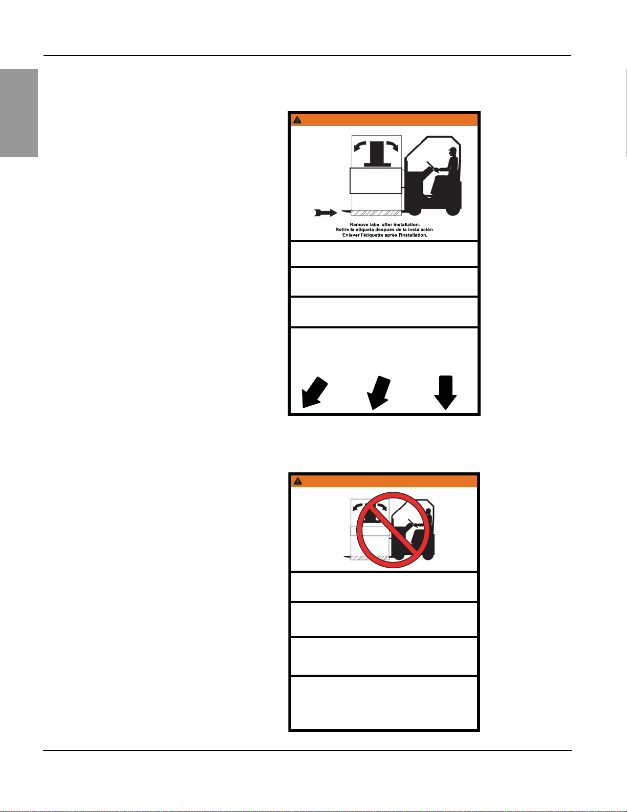
Figure 5 – Front Warning Label, Rainproof Switchboards
tfilkrofottnempiuqeehteruceS .erehpartsytefashtiw opitnóicubirtsidedopiuqeleetejuS alnocsagracatnomlaodatroposotua .iuqadadirugesedaerroc uanoitatummocedlierappa’lrexiF elgnasenucevaruetavélétoirahc .iciétirucésed
WARNING / ADVERTENCIA / AVERTISSEMENT
Forks under entire
equipment.
Horquillas debajo de
todo el equipo.
Fourches sous l’appareil
de commutation entier.
FORK ACCESS
ACCESO DE LAS HORQUILLAS
ACCÈS DES FOURCHES
TIPPING HAZARD UNBALANCED LOAD
Failure to follow these instructions can result in death, serious injury, or equipment damage.
• Ensure proper support under heavy end before moving equipment.
• Secure to forklift with safety strap.
• Asegúrese de que el extremo pesado esté adecuadamente soportado antes de mover el equipo.
• Sujete al montacargas con la correa de seguridad.
El incumplimiento de estas instrucciones puede causar la muerte, lesiones serias o daño
al equipo.
RISQUE DE RENVERSEMENT CHARGE DÉSÉQUILIBRÉE
• Assurez-vous que l’exrémité lourde est soutenue adéquatement avant de déplacer l’appareil.
• Fixer au chariot élévateur avec une sangle de sécurité.
Si ces directives ne sont pas respectées, cela peut entraîner la mort ou des
blessures graves ou des dommages matériels.
PELIGRO DE VUELCO CARGA DESEQUILIBRADA
WARNING / ADVERTENCIA / AVERTISSEMENT
TIPPING HAZARD UNBALANCED LOAD
Failure to follow these instructions can result in death, serious injury, or equipment damage.
• No lifting this side.
• Ensure proper support under heavy end before moving equipment.
• Remove label after installation.
• No lo levante por este lado.
• Asegúrese de que el extremo pesado esté adecuadamente soportado antes de mover el equipo.
• Retire la etiqueta después de la instalación.
El incumplimiento de estas instrucciones puede causar la muerte, lesiones serias o daño
al equipo.
RISQUE DE RENVERSEMENT CHARGE DÉSÉQUILIBRÉE
• Pas de levage de ce côté.
• Assurez-vous que l’extrémité lourde est soutenue adéquatement avant de
déplacer l’appareil.
• Enlevez l’étiquette après l’installation.
Si ces directives ne sont pas respectées, cela peut
entraîner
la mort ou des
blessures graves ou des dommages matériels.
PELIGRO DE VUELCO CARGA DESEQUILIBRADA
REMOVE LABEL
AFTER INSTALLATION

Section 3—Receiving, Handling, and Storing Power-Style™ QED-2 Switchboards
13© 1988–2018 Schneider Electric All Rights Reserved80043-055-13
ENGLISH
When elevating a shipping section not equipped with lifting straps, use an
overhead crane equipped with either of the following:
• A chain coupled to a sling rigging
• A wire cable with safety hooks and shackles
Wrap the sling completely around the switchboard and shipping stringers.
NOTE: A forklift is an alternative method of handling the switchboard. Always
check the fork lengths to ensure that the forks extend under the entire
switchboard. Carefully balance the load, and always use a safety strap when
handling or moving a switchboard with a forklift (Figure 4 on page 12).
Storing
When storing the switchboard before installation, cover the top and openings
of the equipment during the construction period to protect the switchboard from
dust and debris.
If a switchboard is not installed and energized immediately, store it in a clean, dry
space with a consistent temperature to prevent condensation. Store the
switchboard indoors, if possible. Preferably, store it in a heated building with
adequate air circulation and protect it from dirt, fumes, water, and physical
damage. Storing the switchboard outdoors can cause harmful condensation inside
the switchboard.
NOTE: Install portable electric heaters of approximately 250 watts per vertical
section in both indoor-type and rainproof-type switchboard enclosures for
adequate protection during storage.
Before energizing the space heaters, remove all loose packing or flammable
materials inside the switchboard. Outdoor switchboards are not weather-resistant
until completely and properly installed; treat them the same as indoor switchboards
until after installation.
WARNING
TOP HEAVY LOAD—HAZARD OF TIPPING
• Stabilize the shipping section to reduce the possibility of tipping.
• Consult with a certified rigging and lifting expert for any situation not covered
in these instructions.
Failure to follow these instructions can result in death or serious injury.

Power-Style™ QED-2 Switchboards Section 4—Installation
14 © 1988–2018 Schneider Electric All Rights Reserved 80043-055-13
ENGLISH
Section 4—Installation
Correct installation of Power-Style QED-2 switchboards is essential for proper
operation of all switchboard components. Study the associated instruction books
and all drawings carefully. In most cases, all drawings are sent to the purchaser
before a switchboard is shipped to enable adequate planning.
NOTE: The top of the switchboard will not support the weight of the installer.
Location
Find the designated area on the building floor plan where the switchboard will be
installed. The location chosen for installation should provide working clearances
complying with Section 110-26 of the National Electrical Code® (NEC®) or Section
2-308 of the Canadian Electrical Code (CEC) Part 1.
• Front-accessible switchboards require field connections, including mains,
branches, ground bus, and neutral bus, to be accessible and maintainable from
the front.
• For switchboards having rear ventilation, allow a minimum 1/2-in. (13 mm)
clearance between the rear of the switchboard and the wall for proper ventilation.
Equipment drawings identify switchboards requiring rear or side access.
• Switchboards that require rear access for installation, field connections, or
maintenance (such as filter replacement), require 30 in. (762 mm) of working
space per NEC 110-26.
• If the switchboard is in a wet location or outside of the building, enclose it in an
outdoor enclosure or equipment to prevent moisture or water from entering and
accumulating within the enclosure. Outdoor-rated switchboards drain to the
rear, so there must be at least a 1/2-in. (13 mm) clearance between the rear of
the switchboard and a wall or other obstruction for proper drainage.
Foundation Preparation
The floor or foundation must be strong enough to support the weight of the
switchboard without sagging. The surrounding floor area should gently slope
toward a drain.
NOTE: For seismic qualifications, read the section “Anchoring for Seismic
Qualifications” on page 18 before pouring the floor or foundation.
Power-Style QED-2 switchboards are assembled on true and level floors at the
assembly plant. To ensure correct bus bar alignment, the mounting pad or final
installation site must be smooth and level. If parallel steel floor channels are
imbedded for mounting the switchboard, take extra care to ensure the floor channels
are level over their entire length to avoid distortion of the switchboard structure. Each
channel should be level with the finished floor.
When pouring the foundation, make provisions for conduits entering the
switchboard from below and carrying the incoming and/or outgoing cables, control
wiring, and ground cable. The bottom view in the equipment drawing shows the
available conduit area for correct layout.
Conduits should project above the finished floor by about 2 in. (51 mm). However,
to simplify moving the shipping sections into place, install the conduits flush with
the concrete and, after the sections are in their final position, add the appropriate
extension sleeves. Otherwise, raising the shipping section on timbers or lifting it by
a crane to clear the conduit hubs will be necessary. Before pouring the foundation,
consider installing additional conduits for future circuits.

Section 4—Installation Power-Style™ QED-2 Switchboards
15© 1988–2018 Schneider Electric All Rights Reserved80043-055-13
ENGLISH
Switchboard Preparation
Remove dirt and debris from the foundation and surrounding area before moving
the switchboard into final position.
After the switchboard has been moved to its final installation site, take each
shipping section off its shipping stringers. For switchboards greater than 24 in.
(610 mm) deep, the center base channel can be removed.
Remove all packing materials. If the switchboard is equipped with a bottom closure
plate in each vertical section, remove and retain the plates for reuse. When bottom
closure plates are furnished, the customer must make any holes necessary for
conduit entering the bottom of the switchboard. After making the holes, reinstall the
closure plate.
General Installation
Install the switchboard into its final position by leveling progressively each section
and bolting the frames together, if separated. Position shipping sections as follows:
1. Maneuver each shipping section into the desired position using the procedures
under “Handling” on page 9.
2. Carefully lower the section over the conduit stubs to comply with the “available
conduit area” as shown in the bottom view of the equipment drawings.
Otherwise, there might not be sufficient cable bending space.
3. Level the shipping section.
4. After installation of each section is complete, make the through bus splice
connection to the preceding section before installing the next section.
NOTIC
E
HAZARD OF IMPROPER STRESS ON BUS
Level and align adjacent shipping sections with one another. Ensure proper
alignment of horizontal main through bus and proper splice bus connections.
Failure to follow these instructions can result in equipment damage.

Power-Style™ QED-2 Switchboards Section 4—Installation
16 © 1988–2018 Schneider Electric All Rights Reserved 80043-055-13
ENGLISH
Joining Shipping Sections—Outdoor Switchboards
1. Remove the center top cap (Figure 6) from the left-hand section, and retain all
hardware for reuse.
2. When possible, open or remove the front and rear doors and panels, providing
access to bolt adjacent shipping sections together.
3. Remove three 0.5-in. (13 mm) diameter knockouts from the front vertical corner
channel and three from the rear vertical corner channel (a total of six per frame
side) as indicated by the arrows in Figure 6.
4. Position each adjacent section, carefully leveling it and aligning it with the
previous section. If lifting straps are provided, completely remove them from
the sides being bolted together so the sections can be joined flush. The only
gasket required between sections is provided on the roof flange.
Figure 6 – Joining Adjacent Sections—Outdoor Switchboards
Center top cap
See Detail A
Knockouts
(typically 6 places)
See Detail B
Left-hand
section top
plate
Center top cap
Right-hand
section top
plate
Typical:
1/4-20 x 1-1/4 in. slotted
pan head screw, 1/4 in. flat
washer, and 1/4-20 hex nut
Installed
gasketing
Typical:
1/4-20 x 5/8 in.
slotted pan head
screw, 1/4 in. flat
washer, and
1/4-20 hex nut
3/8-16 x1 in.
cap screw
3/8 in. external
tooth lock washer
3/8-16 hex nut
3/8 in. helical
lock washer
Left-hand
section
Right-hand
section
Detail A Detail B

Section 4—Installation Power-Style™ QED-2 Switchboards
17© 1988–2018 Schneider Electric All Rights Reserved80043-055-13
ENGLISH
NOTE: If lifting strap removal is not required to join sections, leave the
lifting strap on the switchboard. Verify that the bolt is tight to maintain
NEMA Type 3R integrity.
5. Six bolts (3/8-16 x 1 in.) are provided. Place them through the holes created in
step 3 to join adjacent sections.
6. Make the through bus splice connections to the preceding section.
7. Replace the center top cap removed in step 1.
8. Replace and secure the front and rear doors and panels removed in step 2.
Joining Shipping Sections—Indoor Switchboards
1. Position each adjacent section, carefully leveling and aligning it with the
previous section. If lifting straps are provided, completely remove them from
the sides being bolted together so the sections can be joined flush.
NOTE: Leave the other lifting straps on the switchboard if their removal is
not required to join adjacent sections flush.
2. Open or remove the front and rear doors and panels, providing access to bolt
adjacent shipping sections together.
3. Six bolts (3/8-16 x 1 in.) are provided. Place the bolts through the existing holes
in the front and rear vertical corner channels to join adjacent sections (Figure 7).
4. Make the through bus splice connections to the preceding section.
5. Replace and secure all front and rear doors and panels removed in step 2.
Figure 7 – Indoor Switchboards
Arrows indicate holes
to use in step 3.

Power-Style™ QED-2 Switchboards Section 4—Installation
18 © 1988–2018 Schneider Electric All Rights Reserved 80043-055-13
ENGLISH
Anchoring for Seismic Qualifications
QED-2 equipment that is seismically certified has been qualified to the site-specific
seismic requirements of the listed model building codes and/or standards. Optional
construction features may be required, depending on the location of the installation and
the particular code and/or standard of interest. Seismic certificates of compliance are
provided with all seismically certified QED-2 equipment. To maintain the validity of this
certification, anchorage of equipment to the primary building structure is required.
Responsibility for Mitigation
of Seismic Damage For the purposes of the model building codes, QED-2 equipment are considered
nonstructural building components. Equipment capacity was determined from triaxial
seismic shake table test results as defined in the International Code Counsel
Evaluation Service (ICCES) Acceptance Criteria for Seismic Qualification Testing of
Nonstructural Components (AC156). Unless otherwise indicated, an equipment
importance factor of 1.5 (Ip = 1.5) was used, indicating that equipment functionality was
verified before and after shaker table seismic simulation testing. This importance factor
is indicative of critical facilities where maximizing the probability of post event
functionality is a priority. ASCE/SEI 7 recognizes AC 156 as an appropriate
methodology for qualifying equipment to its requirements.
Incoming and outgoing cable and conduit must also be considered as related but
independent systems. They must be designed and restrained to withstand the forces
generated by the seismic event without increasing the load transferred to the
equipment. This system must be able to transfer the loads created by a seismic
event to the load-bearing path of the building structural system.
Maintaining Seismic
Certification Seismic qualification of nonstructural components by Schneider Electric is just one
link in the total chain of responsibility required to maximize the probability that the
equipment will be intact and functional after a seismic event. During a seismic event,
the equipment must be able to transfer the loads that are created through the
mounting pad and anchorage to the load-bearing path of the building structural
system. The design engineer of record is responsible for detailing the equipment
connection and anchorage requirements for the given installation. The installer and
manufacturers of the anchorage restraint system are responsible for assuring that
the mounting requirements are met. Schneider Electric is not responsible for the
specification and performance of these systems.
Table of contents
Languages:
Other Square Switch manuals

Popular Switch manuals by other brands


Planet
Planet GS-5220-24T4XVR user manual

AVPro Edge
AVPro Edge conferX AC-CX84-AUHD user manual

TV One
TV One MX-3141PCA instruction manual

Black Box
Black Box ServSwitch Uno USB Installation and use

q-Tech
q-Tech QSW-6900-56LF Series Hardware installation and reference guide

Planet
Planet FSD-1605 user manual


