SSB-Electronic SUPER AMP GaAsFET Series User manual

SP-6/ SP-2000/ SP-220/ SP-7000
SUPER
AMP
GaAsFET
SERIES
50,144,220
&432/435 MHz.
Mast-Mounted Preamplifiers
Thank
you for
purchasing
this
preamplifier
which
is
manufactured
by
SSB
ELECTRONIC
GmbH.
'Ve
believe
that
it
is
without a
doubt
the best available
anywhere
aDd would ask
that
you please spend afew
moments
10
read
through
these notes
in
order
to
ensure
that
you
obtain
the
very best possible results
from tbis
product.
The
full potential
of
this
preamplifier
can only be realized when a
minimum
of
feed line exists between
the
preamplifier
input
and
the
antenna
feed point.
Maximum
lengths are:
24
flo
on SO/144MHz
and
IS ft. on
432MHz
assuming
that
a
quality
coax. such as
AIRCOM
PLUS
is
used.
This
length can
usually
be
achieved
by
mounting
the
preamplifier
on the
support
mast
close to
the
antenna
mounting
point.
The
amplification factor
of
this
preamplifier
can be
adjusted
so
that
agood system gain distribution can
be
maintained.
This
is
important
in
order
to
insure
that
the receiver front-end as well as
tbe
mixer
are
not overloaded.
The
following table may
be
used as aguide
for
setting
the
preamplifier
gain to overcome
the
feedline losses
encountered
from
your
rig to
the
preamp.
'-
CABLE
LOSSES
Under
2dB
2 - 3
dB
Over 3
dB
GAIN
SETTING
M1N
MID
M~,\(
The
following table may be used as aguide to
the
losses for
various
cable
types:
Frequencv
144 MHz.
432
MHz
RG58V
0.2 dB/M
0.4 dB/M
RG213
0.08
dB/m
0.15
dB/m
AIRCOM
PLUS
0.05 dB/M
0.08 dB/M
Agood
rule
oftbumb
is to
aim
for
12
-14
dB.
of
gain above feed line losses.
Access to
the
gain
adjusting
potentiometer
is
obtained
by removing
the
four
self
tapping
screws from
the
underside
of
the unit.
This
enables the plastic
weather
shield to
be
removed
exposing
the
tin plated
shielded box in which asmall hole will be found.
Adjustment
may
now
be
made
with asmall
screw·
driver.
CAUTION:
Great
care
should
be taken when
making
this
adjustment
noting:
a)
The
potentiometer
only
rotates
through
270 deg.
b)
Do
not
exert
any
pressure
on the
adjuster
c)
Ensure
the
screwdriver
goes to
the
pot,
and
does
not
slip sideways
causing
possible
damage
to
any
surrounding
components. An insulated
trimming
tool would be
best
suited
for this job!
If
the tin plate box lid
is
removed to
make
this
adjustment
then please DO
NOT
TOUCH
ANY
OTHER
CONTROLS as these have all been carefully set at
the
factory for
the
best noise figure.
124 Cherrywood Drive., Mountaintop, Pa. 18707 (570)-868-5643
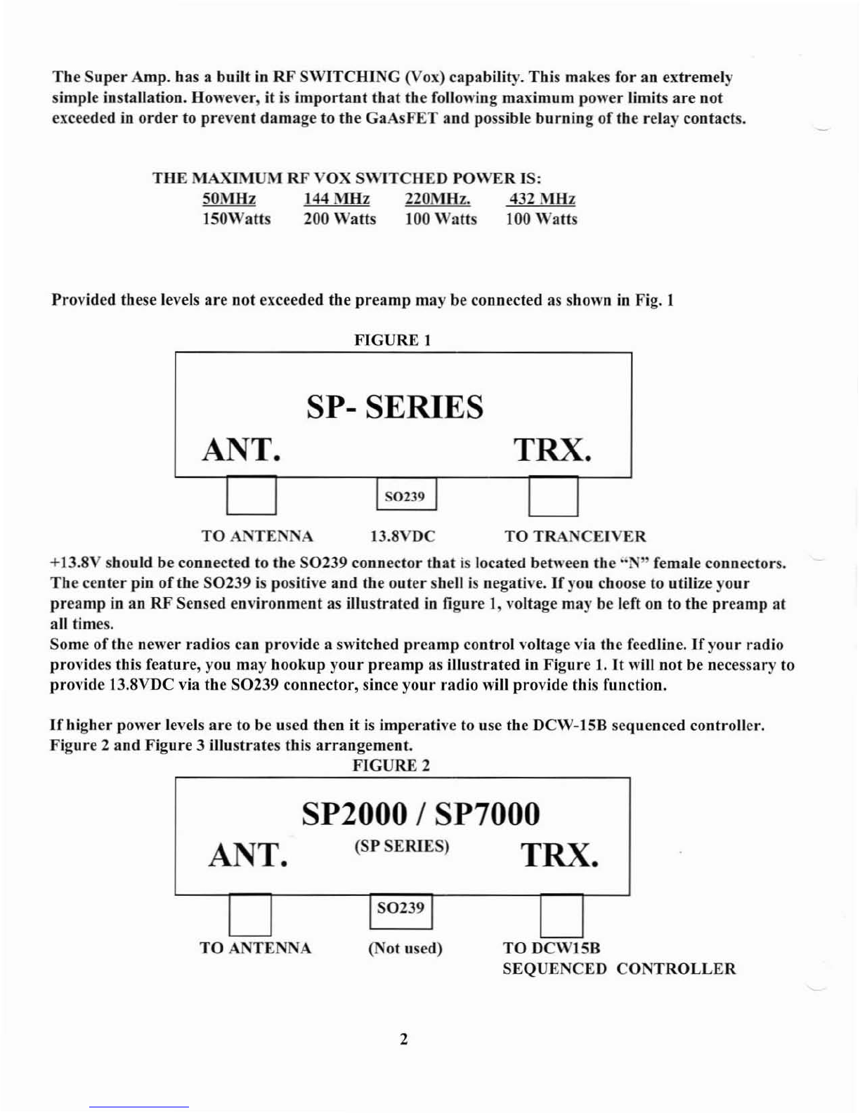
The
Super
Amp. has abuilt in
RF
S\VITCHING (Vox) capability. This makes for an extremely
simple installation. However, it is
important
that
the following maximum power limits
are
not
exceeded
in
order
to prevent
damage
to the
GaAsFET
and possible
burning
oUhe
relay contacts.
THE
MAXIMUM
RF
VOX
SWITCHED
POWER
IS:
SOMHz 144
MHz
220M Hz. 432 MHz
IS0Watts 200
Watts
100 Watts 100 Watts
Provided these levels
are
not
exceeded the
preamp
may be connected
as
shown
in
Fig. 1
FIGURE
I
SP-SERIES
ANT. TRX.
II
50239
I
TOANTE
NA
13.8VDC
TO
TRA
'CEIVER
+13.8V should
be
connected to the
S0239
connector
tbat
is
located between the
"N"
female connectors.
The
center pin
of
the
50239
is positive
and
the
outer
shell
is
negative.
If
you choose to utilize
your
preamp
in
an RF Sensed
environment
as illustrated
in
figure t, voltage may
be
left on to the
preamp
at
all times.
Some of the newer radios can provide aswitched
preamp
control voltage via the
feedline.lfyour
radio
provides this feature,you may hookup
your
preamp
as illustrated in Figure
t.
It
will not be necessary to
provide 13.8VDC via the
50239
connector, since
your
radio will provide this function.
Ifhigher
power levels
are
to
be
used tben it is imperative to use the DC\V-15B sequenced controller.
Figure 2and Figure 3illustrates this
arrangement.
FIGURE
2
SP2000 /SP7000
ANT. (SP
SERIES)
TRX.
1
S0239
1
TO
ANTENNA (Not uscd)
2
TO
DCWlSB
SEQUENCED
CONTROLLER

(Usually aGround on IrlInsmll.
or
+ \ oils on Transmit).
///
/
/~
J/ /
SP2000 ISP7000 ISP-220
SUPER·AMP SEQUENCED GROUND
ON
TRANSMIT
CONTROL
LINE
FROM
DeW-IS
FOR
LINEAR
Ai\lPl..InER
CONTROL.
Pr~Amp
Pin 2TRX(PA)
RANSCEIVEI
DCWI5-B
LINEAR
AMP
Pin ,,' \
rnNTROI
LINE
fDn,'\,
nUNc;::rqVJ'R
,
FIGURE
3
SP-2000, SP-7000, SP-6, SP-220
HIGH
POWER
HOOK-UP
CW/SSB
ATV
"-
By
utilizing
our
DC\V-158
Sequenced
Controller,
the
SP
SERJI!:S
of
Pre-amplifiers can
be safely used in ahigh power
environment.
The
maximum
sequenced
power
levels
are:
50~'IHz.
144MHz 220M Hz.
432MHz
650Walls 750
Walls
650
Walls
500
Walls
150
Walls
The
DeW-ISB
SEQUENCER
provides sequenced control
afyaur
Linear
Power amplifier.
It
guarantees
tbat
preamplifier
switchover occurs
prior
to linear amplifier
turn-on.
The
DC\VJS-B insures
that
hot-
switching
of
the
coaxial relays at elevated pO\\'er levels will not
take
place.
The
DC\V-lSB
has abuilt
in
low
loss BIAS
"T"
that
provides
the
preamplifier
control voltage via
the
feedline
thus
eliminating
the
addi-
tional expense
of
another
cable. In addition, the DCW15-B allows
front
panel switch selection
of
Linear
amplifier
In/Out
and
Preamplifier
In/Out
functions.
DCW-IS
BD-Sub
Connector
Pin-outs
Pi" 1
Ground Ground
Pill
2PA
Control
Provides asequenced
ground
on
transmit
via arelay
contact
to control
Linear
Amplifier
turn
on.
This
function
is
bypassed
when
Linear
amplifier
OUT
has been selected via the front panel.
Pi"
3
PIT
Line I
Grounding
this line
starts
sequencer
functions.
If
your
rig
provides a
ground
on
transmit
via a
PTT
jack,
connect
your
rig's
PIT
line to PIN 3.
3

Pi"
4
PIT
Line 2Some
rig's
do
not
provide a
ground
on
transmit
to control
other
auxilliary
equipment.
If
your
rig provides
+Von
transmit,
connect
the+V
line to Pin 4.
+V
on this pin
starts
the
sequencer
function.
Do
Dot
exceed 13.8VDC
Pi" 5+13.8V
Pi" 6
Ground
Connect
to +13.8V
Ground
c
"~
TRX(PA)
PreAmp
._5
0 0
••
••
-3
••
6-
••
-I
'-
DC\V 15 B
Rear
Panel
TRX
(PA) N(F) -
If
a
Linear
Power Amplifier
is
being used -connect to the
Power
Amplifier RF
Output.
If
only a
tranceiver
or
a
transverter
is
being used, connect to the
RF
output
of
the
trans
ceiver
or
transverter.
Pre
Amp
N(F)
-
The
feedJine from
the
preamp
should be connected here. +13.8VDC will be
pres~'ct
during
receive cycles
00
the
centcr
pin
oft"'!
""N"
connector.
NOTE:
13.8VDC will not be
present
if
Preamplifier
OUT
was selected.
Note:
This
preamplifier
has been designed with failsafe
circutry.
\Vhen
power
is
not applied to
the
preamp
or
the
DC\VlSB,
the
preamp
is
not in line.
Please
insure
that
the
cables
that
you use
arc
assembled properly.
Insure
that
the
center
pin
of
your
'"N"
connectors
are
centered
and
do
not
protrude.
Replacement
of
arelay can get expensive!
Should you
ever
have
any
questions concerning
the
operation
or
the
hook up
of
your
SP
SERIES
Preamplifier
or
your
DC\V-ISB
Sequencer,
please do not hesitate to
contact
us.
73's
Gerry
Rodski
K3MKZ
SSB
ELECTRONIC
USA
570-868-5643
45P2000

J
"
This manual suits for next models
4
Table of contents


