SSS Siedle PL 001 User manual

Produkt-
information
Pollerleuchte
PL 001
PL 002
Bollard lamp
PL 001
PL 002
Luminaire sur pilier
PL 001
PL 002
Delimitatore luminoso
PL 001
PL 002
Bolderlamp
PL 001
PL 002
Pullertlampe
PL 001
PL 002
Pollare
PL 001
PL 002
Sloupkové svítidlo
PL 001
PL 002

1
2

10 11/13
3/12 4

2
Deutsch
Installation
Lieferumfang der PL 001
1
aStele kpl. mit Bodenflansch
bFrontblende
Ein Satz Montagezubehör
bestehend aus:
c3 x Schraubenabdeckung
d3 x Sechskantschrauben
M10 x 80 DIN 24017
e3 x U-Scheibe DIN 125
f3 x Schwerlastdübel SLM 10 N
gLeuchtenglas weiß-transluszent
mit umlaufender Dichtung für
gestreutes Licht.
hLampenfassung werkseitig vor
installiert
i Verbindungsdose IP 54, werk
seitig vorinstalliert
jInbusschlüssel Gr. 2,5
Lieferumfang der PL 002
2
aStele kpl. mit Bodenflansch
bFrontblende
Ein Satz Montagezubehör beste-
hend aus:
c3 x Schraubenabdeckung
d3 x Sechskantschrauben
M10 x 80 DIN 24017
e3 x U-Scheibe DIN 125
f3 x Schwerlastdübel SLM 10 N
gLeuchtenabdeckung für gerich
tetes Licht
hLampenfassung vorinstalliert
i Verbindungsdose IP 54, werk-
seitig vorinstalliert
jInbusschlüssel Gr. 2,5
Montage
3Leuchtenglas/Leuchtenabdeckung
entfernen
Mit dem beiliegenden Inbus-
Schlüssel die verdeckte Schraube
herausdrehen bis das Leuchten-
glas/Leuchtenabdeckung gekippt
entnommen werden kann.
Die Inbusschraube muss
!danach wieder eingeschraubt
werden.
4Frontblende entfernen
5(ohne Abbildung)
Befestigungslöcher der Stele
anzeichnen
6(ohne Abbildung)
Befestigungslöcher
(12 mm, 60 mm tief) bohren und
Hochlastdübel setzen.
7(ohne Abbildung)
Installationskabel durch die Boden-
platte führen und Pollerleuchte
befestigen. Schraubenabdeckung
aufsetzen.
8(ohne Abbildung)
Anschlussleitung in entsprechender
Länge abmanteln und den elek-
trischen Anschluss fachgerecht
herstellen.
Anschlussdose muss nach der
!Installation in der Stele mon-
tiert, sicher und dicht verschlossen
werden!
9 (ohne Abbildung)
Leuchtmittel einsetzen
10 Frontblende einsetzen
11 Leuchtenglas/Leuchtenab-
deckung einsetzen.
Aussparung muss unten sein.
!
Service
Leuchtmittel wechseln
12 Leuchtenglas/Leuchtenab-
deckung abnehmen und Leucht-
mittel wechseln
13 Leuchtenglas/Leuchtenab-
deckung wieder einsetzen
Technische Daten
•Betriebsspannung 220-240 V AC
•Leuchtmittel max. 23 W
•Vormontierte Verteilerdose IP 54
•Abmessungen:
B x H x T 211 x 844 x 230 mm
Anwendung
Die Pollerleuchte PL 001 und
PL 002, Stele aus Alu- Strangpress-
profil für die freistehende Montage.
Als Gestaltungselement, in Gärten
an Treppen, Wegen, Zufahrten oder
Aufgängen.
Wichtige Hinweise
!
•Die Montage der Pollerleuchte ist
nur auf einem festen Untergrund
z.B. Betonfundament mit “B 25”
oder druckfestem Naturstein
möglich.
Fundamentgröße 50 x 50 x 70 cm
oder eine Bodenplatte von 1 m2
und 15 cm Stärke.
•Mit Zubehör Erdstück
ZE/KSF 611-0 auch zum
einbetonieren geeignet.
•Einbau, Montage und Service
elektrischer Geräte dürfen nur
durch eine Elektro-Fachkraft
erfolgen.
•Elektrische Verbindungen im
Niederspannungsbereich
(bis 1000 V) müssen nach
VDE 0100/DIN 57100 erstellt
werden.
•Die Pollerleuchte darf nur über
die vorinstallierte Leitung
(H05RN-F 1mm2) angeschlossen
werden.
•Das Gerät darf nur in spannungs-
losem Zustand geöffnet werden.
•Um Verletzungen vorzubeugen,
muss das Gerät gemäß den
Montageanweisungen zuverlässig
am Boden befestigt werden.
•Leuchtmittel mit E27 Sockel und
integriertem Vorschaltgerät
einsetzen Typ TC-DSE
z.B. Osram Dulux EL (DEL LL 20)

3
English
Installation
Application
The bollard lamp PL 001 and
PL 002, pedestal made of sectional
extruded aluminium for free-
standing installation. As a design
element, in gardens, on steps,
paths, drives or walkways.
Important notes
!
•The bollard lamp can only be
mounted on a firm basis such as a
concrete foundation complying to
“B 25” or compression resistant
natural stone.
Foundation size 50 x 50 x 70 cm or
a floor plate of 1 m2and 15 cm in
thickness.
•Also suitable for concreting in
when used in conjunction with
ground accessory ZE/KSF 611-0.
•Electrical appliances may only be
installed, mounted and serviced by
suitably qualified electrical
engineers.
•Electrical connections in the low-
voltage range (up to 1000 V) must
be made in accordance with
VDE 0100/DIN 57100.
•The bollard lamp may only be
connected using the pre-installed
cable (H05RN-F 1mm2).
•The device may only be opened
when not live.
•In order to prevent injury, the
device must be reliably secured to
the ground as indicated in the
installation instructions.
•Light sources with E27 socket
and integrated ballast, type used
TC-DSE, e.g. Osram Dulux EL (DEL
LL 20)
Scope of delivery of the PL 001
1
aPedestal complete with floor
flange
bFront panel
One mounting accessory set
comprising:
c3 x screw covers
d3 x hexagonal screws
M10 x 80 DIN 24017
e3 x flat washers DIN 125
f3 x heavy-duty floor plug
SLM 10 N
gWhite translucent glazing panel
with all-round seal for scattered
light.
hPrefitted lampholder
i Prefitted IP 54 splitting box,
jAllen key size 2.5
Scope of delivery of the PL 002
2
aPedestal complete with floor
flange
bFront panel
One mounting accessory set
comprising:
c3 x screw covers
d3 x hexagonal screws
M10 x 80 DIN 24017
e3 x flat washers DIN 125
f3 x heavy-duty floor plug
SLM 10 N
gLamp cover for directed
light
hPrefitted lampholder
i Prefitted IP 54 splitting box,
jAllen key size 2.5
Mounting
3Remove the glazing panel / lamp
cover
Using the provided Allen key, back
out the concealed screw until the
glazing panel/light cover can be
tilted and removed
Remember to replace the
!Allen screw afterwards
4Remove the front panel
5(not illustrated)
Mark in the fastening holes of the
pedestal
6(not illustrated)
Drill the fastening holes (12 mm,
60 mm deep) and set the heavy-
duty floor plugs
7(not illustrated)
Guide the installation cable through
the floor plate and fasten the
bollard lamp. Position the screw
cover.
8(not illustrated)
Strip the connecting cable over a
suitable length and correctly carry
out the electrical connection.
After installation, the junction
!box must be securely mounted
in the pedestal and sealed shut.
9 (not illustrated).
Insert the light source.
10 Insert the front panel
11 Insert the glazing panel / lamp
cover.
The recess must be
!at the bottom.
Servicing
Exchanging the light source
12 Remove the glazing panel/lamp
cover and change the light source
13 Replace the glazing panel/lamp
cover
Specifications
•Operating voltage 220-240 V AC
•Light source max. 23 W
•Prefitted splitting box IP 54
•Dimensions:
W x H x D 211 x 844 x 230 mm

4
Français
Installation
Application
Les luminaires sur pilier PL 001 et
PL 002, la stèle en profilé
d'aluminium extrudé pour montage
isolé. En tant qu'élément de
configuration, dans les jardins, sur
les escaliers, allées, voies ou rampes
d'accès.
Remarques importantes
!
•Le montage du luminaire sur pilier
n'est possible que sur un support
résistant pouvant être des
fondations en béton, classe de
résistance “B 25”, ou de la pierre
naturelle résistant à la pression.
Dimensions des fondations
50 x 50 x 70 cm ou une dalle de
1 m2et 15 cm d'épaisseur.
•Avec l'accessoire pièce de terre
ZE/KSF 611-0, peut également être
scellé dans le béton.
•L'installation, le montage et
l'entretien d'appareils électriques
ne doivent être réalisés que par un
spécialiste en électricité.
•Les branchements électriques
dans la plage des basses tensions
(jusqu'à 1000 V) doivent être
réalisés selon VDE 0100/DIN 57100.
•Le luminaire sur pilier ne doit être
raccordé que par l'intermédiaire du
câble préalablement installé
(H05RN-F 1mm2).
•L'appareil ne doit être ouvert qu'à
l'état hors tension.
•Pour éviter tout risque de
blessures, l'appareil doit être fixé au
sol de façon fiable, conformément
aux instructions de montage.
•Utiliser une lampe avec socle E27
et ballast intégré, type TC-DSE, p.
ex. Osram Dulux EL (DEL LL 20)
Etendue de la fourniture PL 001
1
aStèle complète avec bride de
fixation au sol
bFaçade
Un kit d'accessoires de montage
composé de :
c3 capots vissables
d3 vis à tête hexagonale
M10 x 80 DIN 24017
e3 rondelles en U DIN 125
f3 chevilles pour charges lourdes
SLM 10 N
gVerre de lampe blanc
transparent avec joint
périphérique pour lumière
diffusée.
hDouille de lampe pré-installée en
usine
i Boîte de raccordement IP 54,
pré-installée en usine
jClé mâle coudée pour vis à six
pans creux, taille 2,5
Etendue de la fourniture PL 002
2
aStèle complète avec bride de
fixation au sol
bFaçade
Un kit d'accessoires de montage
composé de:
c3 capots vissables
d3 vis à tête hexagonale
M10 x 80 DIN 24017
e3 rondelles en U DIN 125
f3 chevilles pour charges lourdes
SLM 10 N
gCache-lampe pour lumière
dirigée
hDouille de lampe pré-installée
i Boîte de raccordement IP 54,
pré-installée en usine
jClé mâle coudée pour vis à six
pans creux, taille 2,5
Montage
3Retirer le verre de lampe / cache-
lampe
A l'aide de la clé mâle coudée pour
vis à six pans creux fournie, dévisser
la vis masquée jusqu'à ce qu'il soit
possible de faire basculer le verre
de lampe/cache-lampe.
Il faut ensuite revisser la vis à
!six pans creux.
4Retirer la façade
5(non illustré)
Tracer les orifices de fixation de la
stèle
6(non illustré)
Percer les orifices de fixation (12
mm, profondeur 60 mm) et placer
les chevilles pour charges lourdes.
7(non illustré)
Faire passer le câble d'installation
dans la semelle et fixer le luminaire
sur pilier. Placer le capot vissable.
8(non illustré)
Dénuder le câble de raccordement
sur la longueur voulue, et établir le
raccordement électrique dans les
normes.
La boîte de raccordement doit,
!après installation dans la stèle,
être fermée de façon sûre et
hermétique!
9 (non illustré)
Mettre la lampe en place
10 Mettre la façade en place
11 Mettre le verre de lampe /
cache-lampe en place.
L'évidement doit se trouver en
!bas.
Entretien
Remplacement de la lampe
12 Déposer le verre de lampe /
cache-lampe et remplacer la lampe
13 Remettre en place le verre de
lampe / cache-lampe
Caractéristiques techniques
•Tension de service 220-240 V CA
•Lampe max. 23 W
•Boîte de distribution prémontée,
IP 54
•Dimensions:
La x H x P 211 x 844 x 230 mm

5
Italiano
Installazione
Modo d’uso
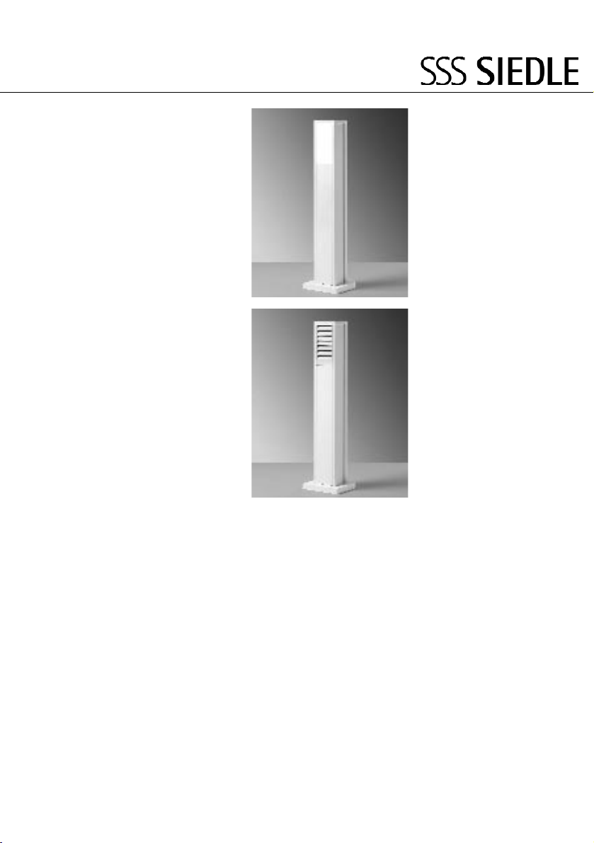
Delimitatori luminosi PL 001 e
PL 002, steli in profilato estruso di
alluminio per montaggio auto-
nomo, come elementi decorativi in
giardini, su scale, percorsi, vie
d’accesso o salite.
Avvertenze importanti
!
•Il montaggio dei delimitatori
luminosi può avvenire esclusiva-
mente su una base solida, ad es.
una fondazione in calcestruzzo con
“B 25” oppure su pietra naturale
resistente alla compressione.
Fondazione con dimensioni di
50 x 50 x 70 cm oppure soletta in
calcestruzzo di 1 m2e 15 cm di
spessore.
•Con accessorio per messa a terra
ZE/KSF 611-0 idoneo anche per
l’eventuale muratura nel
calcestruzzo.
•L’installazione, il montaggio e
l’assistenza degli apparecchi elettrici
possono essere eseguiti esclusiva-
mente a cura di elettricisti
specializzati.
•I collegamenti elettrici nella
gamma di bassa tensione
(fino a 1000 V) devono essere
eseguiti secondo la norma
VDE 0100/DIN 57100.
•Il delimitatore luminoso può
essere collegato esclusivamente
tramite il cavo pre-installato
(H05RN-F 1 mm2).
•L’apparecchio può essere aperto
solo in assenza di tensione.
•Per prevenire eventuali lesioni,
occorre fissare l’apparecchio
saldamente al pavimento secondo
le istruzioni di montaggio.
•Utilizzare il mezzo
d’illuminazione con zoccolo E27 e
alimentatore tipo TC-DSE
ad es. Osram Dulux EL (DEL LL 20)
Kit di fornitura del PL 001
1
aStele completa di flangia a
pavimento
bPannello frontale
Un set di accessori di montaggio
costituito da:
c3 x copertura a vite
d3 x viti esagonali
M10 x 80 DIN 24017
e3 x rosette DIN 125
f3 x tasselli per carichi pesanti
SLM 10 N
gVetro del mezzo d’illuminazione
bianco traslucente con
guarnizione perimetrica per
luce diffusa.
hSupporto del mezzo
d’illuminazione luminoso
pre-installato in fabbrica
i Scatola di collegamento IP 54,
pre-installata in fabbrica
jChiave per viti ad esagono cavo
misura 2,5
Kit di fornitura del PL 002
2
aStele completa di flangia a
pavimento
bPannello frontale
Un set di accessori di montaggio
costituito da:
c3 x copertura a vite
d3 x viti esagonali
M10 x 80 DIN 24017
e3 x rosette DIN 125
f3 x tasselli per carichi pesanti
SLM 10 N
gCopertura del mezzo
d’illuminazione per luce diffusa
hSupporto del mezzo
d’illuminazione pre-installato
i Scatola di collegamento IP 54,
pre-installata in fabbrica
jChiave per viti ad esagono cavo
misura 2,5
Montaggio
3Rimuovere il vetro/la copertura
del mezzo d’illuminazione.
Svitare la vite nascosta con la chiave
per viti ad esagono cavo finché non
è possibile ribaltare e rimuovere il
vetro/la copertura del mezzo
d’illuminazione.
Successivamente riavvitare
!la vite ad esagono cavo.
4Rimuovere il pannello frontale.
5(senza figura)
Segnare i fori di fissaggio della
stele.
6(senza figura)
Eseguire i fori di fissaggio (12 mm,
profondità 60 mm) e inserire i
tasselli per carichi pesanti.
7(senza figura)
Portare il cavo di installazione
attraverso la soletta del pavimento,
quindi fissare il delimitatore
luminoso. Applicare la copertura a
vite.
8(senza figura)
Togliere la guaina al cavo di
collegamento nella misura appro-
priata e realizzare l’allacciamento
elettrico a regola d’arte.
Dopo l’installazione montare
!la scatola di collegamento nella
stele e sigillarla perfettamente!
9 (senza figura)
Inserire il mezzo d’illuminazione
10 Applicare il pannello frontale
11 Applicare il vetro/la copertura
del mezzo d’illuminazione.
La cavità deve essere sul lato
!inferiore.
Assistenza
Sostituzione del mezzo
d’illuminazione
12 Togliere il vetro/la copertura e
sostituire il mezzo d’illuminazione
13 Rimontare il vetro/la copertura
del mezzo d’illuminazione
Dati tecnici
•Tens. d’esercizio 220-240 V AC
•Mezzo d’illuminazione max. 23 W
•Scatola di distribuzione pre-
montata IP 54
•Dimensioni: larg. x alt. x prof.
211 x 844 x 230 mm

6
Nederlands
Installatie
Leveringsomvang de PL 001
1
azuil cpl. met bodemflens
bvoorscherm
één set montagemateriaal
bestaande uit:
c3 x schroefafdekking
d3 x zeskantbouten
M10 x 80 DIN 24017
e3 x onderlegring DIN 125
f3 x zware pluggen SLM 10 N
glampenglas wit-doorschijnend
met romdom afdichting voor
verstrooid licht.
hlampfitting vanuit de fabriek
voorgeïnstalleerd
i aansluitdoos IP 54, vanuit de
fabriek voorgeïnstalleerd
jinbussleutel maat 2,5
Leveringsomvang van de PL 002
2
azuil cpl. met bodemflens
bvoorscherm één set
montagemateriaal bestaande
uit:
c3 x schroefafdekking
d3 x zeskantbouten
M10 x 80 DIN 24017
e3 x onderlegring DIN 125
f3 x zware pluggen SLM 10 N
glampafdekking voor gericht licht
hlampfitting voorgeïnstalleerd
i aansluitdoos IP 54, vanuit de
fabriek voorgeïnstalleerd
jinbussleutel maat 2,5
Montage
3Lampenglas/lampafdekking
verwijderen
Met de bijgeleverde inbussleutel de
verborgen schroef uitdraaien tot
het lampenglas/ de lampafdekking
gekanteld er uit getrokken kan
worden.
De inbusschroef moet
!daarna weer ingeschroefd.
4Voorscherm verwijderen
5(zonder afbeelding)
Bevestigingsgaten van de zuil
aftekenenen
6(zonder afbeelding)
Bevestigingsgaten (12 mm, 60 mm
diep) boren en zware pluggen
inzetten.
7(zonder afbeelding)
Installatiekabel door de vloerplaat
leiden en bolderlamp bevestigen.
Schroefafdekking er weer opzetten.
8(zonder afbeelding)
Aansluitleiding over de juiste lengte
afstrippen en de elektrische
aansluiting vakkundig aanbrengen.
Aansluitdoos moet na de
!installatie in de zuil
gemonteerd worden, veilig en
waterdicht afgesloten!
9 (zonder afbeelding)
Lamp inzetten
10 Voorscherm inzetten
11 Lampenglas/lampafdekking
inzetten.
Uitsparing moet onder zijn.
!
Service
Verlichting vervangen
12 Lampenglas/lampafdekking
afnemen en Verlichting vervangen
13 Lampenglas/lampafdekking weer
inzetten
Technische gegevens
•Bedrijfsspanning 220-240 V AC
•Lamp max. 23 W
•Voorgemonteerde verdeeldoos
IP 54
•Afmetingen:
b x h x d 211 x 844 x 230 mm
Toepassing
De bolderlamp PL 001 en PL 002,
zuil uit aluminium-extrusieprofiel
voor vrijstaande montage. Als
sierelement, in tuinen bij trappen,
wegen, inritten of opgangen.
Belangrijke aanwijzingen
!
•De montage van de bolderlamp is
alleen op een vaste ondergrond
b.v. betonfundament met “B 25”
of drukvaste natuursteen mogelijk.
Fundamentafmetingen
50 x 50 x 70 cm of een vloerplaat
van 1 m2en 15 cm sterkte.
•Met accessoire-aardstuk
ZE/KSF 611-0 ook voor het in beton
verwerken geschikt.
•Inbouw, montage en service van
elektrische apparaten mogen alleen
door een elektricien plaatsvinden.
•Elektrische verbindingen in het
laagspanningsgebied (tot 1000 V)
moeten volgens VDE 0100/
DIN 57100 uitgevoerd worden.
•De bolderlamp mag alleen via de
voorgeïnstalleerde leiding
(H05RN-F 1mm2)aangesloten
worden.
•Het apparaat mag alleen in
spanningsloze toestand geopend
worden.
•Om verwondingen te voorkomen,
moet het apparaat overeenkomstig
de montageaanwijzigen
betrouwbaar aan de bodem
bevestigd worden.
•Lamp met E27 fitting en
geïntegreerd voorschakelapparaat
inzetten type TC-DSE b.v. Osram
Dulux EL (DEL LL 20)

7
Dansk
Installation
Leveringsomfang PL 001
1
aStander komplet med bund-
flange
bFrontplade
Et sæt montagetilbehør
bestående af:
c3 x skruehætter
d 3 x unbracobolte
M10 x 80 DIN 24017
e3 x underlagsskiver DIN 125
f3 x specialdyvler SLM 10 N
gLygteglas, hvidt gennemsigtigt
med rundgående tætning, for
spredning af lyset
hLampefatning forinstalleret fra
fabrikken
i Samledåse IP 54, forinstalleret
fra fabrikken
j Unbraconøgle str. 2,5
Leveringsomfang PL 002
2
aStander komplet med bund-
flange
bFrontplade
Et sæt montagetilbehør
bestående af:
c 3 x skruehætter
d3 x unbracobolte
M10 x 80 DIN 24017
e3 x underlagsskiver DIN 125
f 3 x specialdyvler SLM 10 N
g Lygteafdækning for retnings-
bestemt lys.
hLampefatning forinstalleret
i Samledåse IP54, forinstalleret
fra fabrikken
j Unbraconøgle str. 2,5
Montage
3Lygteglas/lygteafdækning fjernes.
Med den medfølgende unbraco-
nøgle skrues den skjulte skrue ud,
lygteglasset/lygteafdækningen i
udvippet stilling kan tages ud.
Unbracoskruen skal derefter
!skrues i igen.
4Frontpladen fjernes.
5(Ikke vist).
Monteringshullerne til standeren
opmærkes.
6(Ikke vist).
Monteringshuller (12 mm, 60 mm
dybe) bores og specialdyvler sættes
i hullerne.
7(Ikke vist).
Installationskablet føres gennem
betonpladen (flisen) og pullert-
lampen fastgøres. Husk at sætte
skruehætterne på.
8(Ikke vist).
Tilslutningsledningens yderkappe
fjernes på det nødvendige stykke
og den elektriske tilslutning fore-
tages forskriftsmæssigt korrekt.
Tilslutningsdåsen skal efter
!installationen monteres i
standeren og lukkes sikkert og tæt!
9 (Ikke vist).
Lyskilden monteres.
10 Frontpladen sættes på plads.
11 Lygteglas/lygteafdækning sættes
på plads.
Udsparringen skal vende
!nedad.
Service
Udskiftning af lyskilde
12 Lygteglasset/lygteafdækningen
afmonteres og lyskilden udskiftes.
13 Lygteglasset/lygteafdækningen
sættes på igen.
Tekniske data
•Driftsspænding 220-240 V AC
•Lyskilde maks. 23 W
•Formonteret fordelerdåse IP 54
•Mål:
B x h x d 211 x 844 x 230 mm
Anvendelse
Pullertlampe PL 001 og PL 002,
stander af strengpresset alumi-
niumsprofil til fritstående montage.
Til opstilling og effektiv belysning i
haver, langs gangstier, ved trapper,
på p-pladser, langs opkørsler eller
opgange.
Vigtige bemærkninger
!
•Montage af pullertlampen er kun
muligt på et fast og stabilt underlag
f.eks. et betonfundament med “B
25” eller trykstabil natursten.
Fundamentstørrelse 50 x 50 x
70 cm eller en betonplade (flise)
på 1 m2og 15 cm tykkelse.
•Med tilbehør-nedstøbningsbeslag
ZE/KSF 611-0 (beregnet til
nedstøbning).
•Indbygning, montage og service
af elektrisk materiel må kun fore-
tages af aut. elinstallatører.
•Elektriske forbindelser på lav-
spændingsområdet (indtil 1000 V)
skal udføres iht. særkstrøms-
reglementet.
•Pullertlampen må kun tilsluttes
med den forinstallerede ledning
(H05RN-F 1mm2).
•Pullertlampen må kun åbnes i
spændingsløs tilstand.
•For at undgå personskader skal
pullertlampen være solidt fastgjort
til underlaget iht. montageanvisnin-
gerne.
•Lyskilden skal være forsynet med
E27 sokkel og integreret
forkoblingsenhed type TC-DSE
f.eks. Osram Dulux EL (DEL LL 20).

8
Svenska
Installation
Leveransomfång för PL 001
1
aPelare komplett med fläns
mot underlaget
bFrontskydd
En sats monteringstillbehör
som består av:
c3 x skruvskydd
d3 x sexkantsskruvar
M10 x 80 DIN 24017
e3 x U-skiva DIN 125
f3 x pluggar för stor
belastning SLM 10 N
gLampglas vitt-genomskinligt
med tätning runtomkring för
strött ljus.
hLampinfattningen
förinstallerades vid tillverkningen
i Kopplingsdosa IP 54,
förinstallerad vid tillverkningen
jInnesexkantsnyckel storlek 2,5
Leveransomfång för PL 002
2
aPelare komplett med fläns
mot underlaget
bFrontskydd
En sats monteringstillbehör
som består av:
c3 x skruvskydd
d3 x sexkantsskruvar
M10 x 80 DIN 24017
e3 x U-skiva DIN 125
f3 x pluggar för stora tyngder
SLM 10 N
gLampskydd för riktat ljus
hLampinfattningen är
förinstallerad
i Kopplingsdosa IP 54,
förinstallerad vid tillverkningen
jInnesexkantsnyckel storlek 2,5
Installation
3Ta av lampglaset/lampskyddet
Med hjälp av den bifogade
innesexkantsnyckeln, skruva ur de
förtäckta skruvarna tills
lampglaset/lampskyddet kan tas ut
lutande
Innesexkantsskruvarna måste
sedan skruvas i igen.
4Ta av frontskyddet
5(utan avbildning)
Markera monteringshålen på
pelaren
6(utan avbildning)
Borra monteringshål (12 mm, djup
60 mm) och sätt i pluggar för hög
belastning.
7(utan avbildning) För installations-
kabeln genom underlaget och sätt
fast pollaren. Sätt på skruvskydden.
8(utan avbildning)
Skala av anslutningsledningen på
lämplig längd och utför den
elektriska anslutningen fackmässigt.
Efter installationen måste
!anslutningsdosan monteras in i
pelaren och stängas säkert och tätt!
9 (utan avbildning)
Sätt in lampan
10 Sätt på frontskyddet
11 Sätt in lampglaset/lampskyddet.
Hacket ska befinna sig nertill.
!
Service
Byta ut lampa
12 Ta av lampglaset/lampskyddet
och byt ut lampan
13 Sätt tillbaka
lampglaset/lampskyddet
Tekniska data
•Driftsspänning 220-240 V AC
•Lampa högst 23 W
•Förmonterad fördelningsdosa
IP 54
•Mått:
B x H x D 211 x 844 x 230 mm
Användning
Pollare PL 001 och PL 002, pelare i
alu-strängpressprofil för fristående
montering. Som dekorations-
element, i trädgården på trappor,
vägar, tillfarter eller uppgångar.
Viktiga anvisningar
!
•Monteringen av pollaren kan
endast ske på ett fast underlag,
t.ex. betongfundament med "B25"
eller tryckfast natursten.
Fundamentets storlek
50 x 50 x 70 cm eller en
betongplatta på 1 m2och en
tjocklek på 15 cm.
•Med tillbehör markfäste
ZE/KSF 611-0 även lämpat för
inbetongering.
•Installation, montering och
underhåll av elektriska apparater får
endast utföras av behörig elmontör.
•Elektriska kopplingar inom
lågspänningsområdet (till 1 000 V)
måste utföras enligt
VDE 0100/DIN 57100.
•Pollaren får endast anslutas med
hjälp av den förinstallerade
ledningen (H05RN-F 1mm2).
•Apparaten får bara öppnas i
spänningslöst tillstånd.
•För att förebygga olycksfall måste
apparaten sättas fast ordentligt på
underlaget enligt
monteringsanvisningarna.
•Lampa med E27-sockel och
integrerat förkopplingsdon typ
TC-DSE
t.ex. Osram Dulux EL (DEL LL 20).

9
Česky
Instalace
Použití
Sloupkové svítidlo PL 001 a PL 002,
sloupek z hliníkového výtlačně
lisovaného profilu pro volně stojící
montáž. Jako dekorativní prvek v
zahradách na schodištích, cestách,
vjezdech nebo rampách.
Důležité pokyny
!
•Montáž sloupkového svítidla je
možná pouze na pevném
podkladu, např. na betonových
základech s „B25“ nebo na
přírodním kameni odolném proti
tlaku.
Velikost základů 50 x 50 x 70 cm
nebo základová deska 1 m2,
15 cm silná.
•S příslušenstvím prvek pro
upevnění do země
ZE/KSF 611-0 také vhodný k
zabetonování.
•Instalaci, montáž a servis
elektrických přístrojů smí provádět
pouze odborný elektrikář.
•Elektrická spojení v oblasti
nízkého napětí (do 1000 V) musí
být provedeny podle
VDE 0100/DIN 57100.
•Sloupkové svítidlo smí být
připojeno pouze pomocí
předinstalovaného vedení
(H05RN-F 1 mm2).
•Přístroj smí být otevřen pouze v
beznapěťovém stavu.
•Aby se zabránilo poraněním,
musí být přístroj podle montážních
pokynů upevněn řádně na zemi.
•Používat osvětlovací
prostředky s paticí E27 a
integrovaným předřadníkem typu
TC-DSE, např. Osram Dulux EL
(DEL LL 20).
Rozsah dodávky u PL 001
1
asloupek kompletní s pozemní
přírubou
bčelní clona
sada montážního příslušenství
sestávající z:
c3 x krytka šroubů
d3 x šroub s šestihrannou
hlavou M10 x 80 DIN 24017
e3 x podložka DIN 125
f3 x hmoždinky pro velké
zátěže SLM 10 N
gstínidlo lampy bílo-průsvitné s
celoobvodovým těsněním pro
řízené světlo.
hobjímka žárovky ze závodu
předinstalována
ispojovací krabice IP 54, ze
závodu předinstalována
jimbusový klíč vel. 2,5
Rozsah dodávky u PL 002
2
asloupek kompletní s pozemní
přírubou
bčelní clona
sada montážního příslušenství
sestávající z:
c3 x krytka šroubů
d3 x šroub s šestihrannou
hlavou M10 x 80 DIN 24017
e3 x podložka DIN 125
f3 x hmoždinky pro velké
zátěže SLM 10 N
gkryt lampy pro usměrněné
světlo
hobjímka žárovky
předinstalována
ispojovací krabice IP 54, ze
závodu předinstalována
jimbusový klíč vel. 2,5
Montáž
3 Stínidlo lampy/kryt lampy
odstranit
Přiloženým imbusovým klíčem
skryté šrouby vyšroubovat až
může být vyklopené stínidlo
lampy/kryt lampy vyjmuto.
Imbusový šroub musí být
!poté zašroubován.
4 Čelní clonu odstranit
5(bez vyobrazení)
Označit upevňovací otvory sloupku
6(bez vyobrazení)
Vyvrtat upevňovací otvory (12 mm,
60 mm hluboké) a vsadit
hmoždinky pro velká zatížení.
7(bez vyobrazení)
Instalační kabel protáhnout
základovou deskou a sloupkové
svítidlo upevnit. Nasadit krytky
šroubů.
8(bez vyobrazení)
Přípojné vedení v příslušné poloze
odizolovat a provést odborné
připojení.
Přípojná krabice musí být po
!instalaci namontována ve
sloupku a bezpečně a těsně
uzavřena!
9(bez vyobrazení)
Vsadit osvětlovací prostředek
10 Vsadit čelní clonu
11 Nasadit stínidlo lampy/kryt
lampy
Výřez musí být dole.
!
Servis
Výměna osvětlovacího prostředku
12 Stínidlo lampy/kryt lampy
sejmout a osvětlovací prostředek
vyměnit
13 Stínidlo lampy/kryt lampy opět
nasadit
Technická data
•Provozní napětí 220-240 V AC
•Osvětlovací prostředek
max. 23 W
•Předinstalovaná krabice
rozváděče IP 54
•Rozměry:
Š x V x H 211 x 844 x 230 mm

© 2004/ 07.04
Printed in Germany
Best. Nr. 0-1101/ 034182
S. Siedle & Söhne
Postfach 1155
D-78113 Furtwangen
Bregstraße 1
D-78120 Furtwangen
Telefon +49 723 63-0
Telefax +49 723 63-300
www.siedle.de
This manual suits for next models
1
Table of contents
Languages:
Popular Outdoor Light manuals by other brands

HAMPTON BAY
HAMPTON BAY 5240103 Use and care guide

easymaxx
easymaxx U-DL038 instructions

TECHLIGHTING
TECHLIGHTING Wend 700OSWEND92730 Series installation instructions

HAMPTON BAY
HAMPTON BAY NXT-3149 Use and care guide

HAMPTON BAY
HAMPTON BAY 338-000 instruction manual

Room & Board
Room & Board ROWLAND Assembly instructions

Inspire
Inspire Praia instruction manual

Brooklyn
Brooklyn BR-IP65-WL-GLG quick start guide

Secure Home
Secure Home SH-4150-MB Installation and operating instructions

Home Decorators Collection
Home Decorators Collection DC-C3083 Use and care guide

unios
unios Astro Fixed Two quick start guide

CERNO
CERNO Valeo Assembly instructions