Stab ROTOR SAT HH100i User manual


CONTENTS
- INTRODUCTION ......................................................................................................... page 1
- ROTOR TECHNICAL DATA ..................................................................................... page 2
- INTERFACE TECHNICAL DATA ............................................................................ page 3
- MOUNTING INSTRUCTIONS .................................................................................. page 4
1. Where to install the sat dish .................................................................................... page 4
2. Rotor’s installation.................................................................................................... page 4
3. Connections ................................................................................................................ page 5
3.1 Specifications of the recommended coaxial cable........................................... page 5
3.2 Map to determine the installation parameters - EUROPE MAP ................ page 6
NORTH AFRICA MAP ..................................................................................... page 6a
MIDDLE EAST MAP......................................................................................... page 6b
SOUTH EAST ASIA MAP ................................................................................ page 6c
4. How to find out the elevation angle of the Rotor ................................................. page 7
5. How to find out the elevation value of the dish .................................................... page 7
6. Dish pointing .............................................................................................................. page 7
- USE OF THE REMOTE CONTROL......................................................................... page 10
7. Description of the normal buttons use ................................................................... page 10
8. Description of the special buttons use .................................................................... page 10
9. Storing a satellite position ........................................................................................ page 10
10. Setting and storing the EAST - WEST limits ..................................................... page 11
11. Recalculation function ............................................................................................ page 11
12. Return to the 0° position of the rotor................................................................... page 12
13. Restoring the satellites tables ................................................................................ page 12
- PROBLEMS SOLVING GUIDE ................................................................................. page 13
- WARRANTY CONDITIONS ...................................................................................... page 14
- HOW TO CONTACT US ............................................................................................. page 15
Via Seminiato, 79
44031 AMBROGIO (FE) ITALY
http:// www.stab-italia.com
e-mail: [email protected]
ROTOR SAT HH100i- HH120i
with interface
Rotor Sat HH100i-HH120i instructions manual – page 1
Attention:
•Please read carefully this instructions manual before installing and using it.
•If your receiver includes DiSEqCTM 1.2 protocol, you will not need to connect the interface.
•When you will decide to replace your old receiver with a new one, kindly check if the new receiver
includes DiSEqCTM 1.2 protocol before buying it.
DEAR CUSTOMER,
Congratulations! You are now the owner of STAB ROTOR SAT.
This is the first sat motor developed by STAB in cooperation with EUTELSAT in order to define the
DiSEqCTM 1.2 standard.
The DiSEqCTM 1.2 system is a trademark of EUTELSAT.
All drawings and technical data are STABTM property and can be changed without prior notice.
Rotor Sat HH100i-HH120i instructions manual – page 2
ROTOR TECHNICAL DATA
SPECIFICATIONS
- Operating protocol DiSEqCTM 1.2 Level
- Maximum antenna diameter 100 cm
- Maximum antenna weight 12 Kg
- Antenna support length 125mm
- Rotation angle ±62°
- Rotation speed 1,8°/s(18V) 1,2/s(13V)
- Operating power supply 13 / 18 Vdc
- Consumption in stand-by mode 30mA
- Consumption in operating mode 190mA
- Starting consumption max 350mA
- Operating temperature -40°C +80°C
- Maximum relative humidity 100%
-Programmablepositions 49 satellites
- Preset positions 26 satellites
- Connectors F type
- Connections Sat coaxial cable
- Mechanical limits ±70°
- Software programmable limits from 5° to 62°
- Fine tuning impulse0,1°
- Inclination max 70°
- Weight 3 Kg
OPTION
- Extension for antenna support
SPECIFICATIONS
- Operating protocol DiSEqCTM 1.2 Level
- Maximum antenna diameter 120 cm
- Maximum antenna weight 17 Kg
- Antenna support length 180mm
- Rotation angle ±62°
- Rotation speed 1,1°/s(18V) 0,8/s(13V)
- Operating power supply 13 / 18 Vdc
- Consumption in stand-by mode 30mA
- Consumption in operating mode 190mA
- Starting consumption max 350mA
- Operating temperature -40°C +80°C
- Maximum relative humidity 100%
-Programmablepositions 49 satellites
- Preset positions 26 satellites
- Connectors F type
- Connections Sat coaxial cable
- Mechanical limits ±70°
- Software programmable limits from 5° to 62°
- Fine tuning impulse0,1°
- Inclination max 70°
- Weight 3,2 Kg
ROTOR SAT HH100 ROTOR SAT HH120
OPTIONAL

Rotor Sat HH100i-HH120i instructions manual – page 3
INTERFACE TECHNICAL DATA
Voltage to LNB........................................... 13 / 18 Vcc
Power supply ...................... 230 Vac (110 on request)
Frequency ..............................................50 Hz (60 Hz)
Operating power consumption .......................... 12 W
Power supply in stand-by mode........................... 5 W
Display................................................................. 3 digit
Connectors.......................................................... F type
Connections ...................................... sat coaxial cable
Weight ................................................................... 750 g
Dimensions.......................................71 x 59 x 150 mm
Operating command.................manual or automatic
by remote control
Operating protocol ..............................DiSEqCTM 1.2
WARNING
•Avoid exposure of the interface to rain or humidity as it could cause sparks or electric shocks.
•Do not open the interface and do not touch any components with your hands, screwdrivers or any other
objects as it can cause damage and is extremely dangerous.
•Before operating the motor, make sure that the temperature of the interface is adjusted to that of the
surrounding environment (5°C ÷ 40°C).
•The interface is sensitive to magnetic fields. Therefore keep it away from motors, magnets, etc.
•Place the interface over a flat and stable surface and avoid heavy knocks.
•If the interface drops to the floor, disconnect it immediately from the mains. If after careful examination
there is no damage to the box, you can connect it again. Otherwise if there is evidence of damage, please
contact your local dealer.

MOUNTING INSTRUCTIONS
Rotor Sat HH100i-HH120i instructions manual – page 4
1. Where to install the sat dish
1.1 Choose a position from where the dish can see the SOUTH without any impediments or obstructions.
Buildings, trees, water-pipes etc. can block partially or completely the sat reception.
2. Rotor’s installation
2.1 Fix the supporting pole (ø 50 ÷ 83 mm diameter) in a perfectly
vertical position.
2.2 Use the provided support to fix the rotor to the pole (fig. 1).
It is strictly forbidden to install the motor upside-down.
2.3 Point the rotor position to the south using a compass (fig. 2).
2.4 Assemble the dish according to the manufacturer’s instructions.
2.5 Fixthedishtotherotor’s antenna supportwiththeprovidedbrackets
(fig. 1).
2.6 Align the dish to rotor’s pole indicator (fig. 2 - 3).
2.7 On a coax cable approximately 1,5 m long, set up two F-connectors
(fig. 4) and connect the LNB to the rotor’s LNB plug (fig. 5 - cable 1).
2.8 Fit an F-connector on each end of the cable going to the interface
(fig. 4) and connect the rotor’s REC plug to the MOTOR plug of
the interface (fig. 5 - cable2).
Warning: - See cable specifications on page 5.
2.9 With the provided shorter cable connect the REC plug of the
interface to the input plug of your receiver (fig. 5 - cable 3).
MINIMUM
HEIGHT
TO AVOID
VIBRATION
FIG. 1
F-CONNECTOR
3 mm
15 mm
8 mm
FIG. 2
FIG. 3
FIG. 4
SOUTH

3. Connections (fig. 5)
Rotor Sat HH100i-HH120i instructions manual – page 5
cable n. 2 cable n. 1
cable n. 3
(provided)TV
LNB
RECEIVER
ANT. 2
ANT. 1
REC LNB
3.1 Specifications of the recommended coaxial cable
CABLE
LENGTH TO 30 M
(to 98.4 feet) FROM 30 TO 60 M
(from 98.4 to 196.8 feet)
Cable type sat coaxial cable sat coaxial cable
Inner conductor CU ø=1,02 mm CU ø=1,13 mm
Inner conductor resistance 22 ohm/Km 18 ohm/Km
Outside conductor resistance 22 ohm/Km 10 ohm/Km
A bad quality cable can prejudice the motor correct working!
Please follow the next specifications:
cable n. 3
REC MOTOR
REMOTE CONTROL
INTERFACE
cable n. 1
(provided)
cable n. 2
FIG. 5 RECEIVER ROTOR LNBINTERFACE


Rotor Sat HH100i-HH120i instructions manual – page 7
4.1 Find out your own geographical position on the map on page 6, 6a, 6b, 6c, note the latitude value
and set the rotor angle to this value (fig. 6).
Example: - Venice 45,5° Latitude NORTH (fig. 6)
4. How to find out the elevation angle of the Rotor
5. How to find out the elevation value of the dish
6. Dish pointing
FIG. 7
FIG. 6
REFERENCE GRID 45
55
65
30 25 2015
6.3 With the interface’s remote control (see paragraph 7: USE OF
THE REMOTE CONTROL), move the rotor by short impulses
Eastwards or Westwards to reach the calculated value.
To coordinate this operation it is necessary that the interface is
near the dish or that somebody can assist you: while the first
one uses the remote control near the interface, the other one
will inform when the dish has reached the correct position on
the graduated scale of the rotor.
Example: VENICE - around 6,9° EAST - (fig. 8)
FIG. 8
ex. VENICE 6,9°
5.1 With the same latitude value, calculate the elevation of the dish (fig. 7) according to the following
formula: Degrees of dish elevation = P – (60 – latitude)
P = degrees of dish elevation for fixed mount given by the manufacturer.
Example: - Latitude Venice = 45,5°
P (dish elevation given by the manufacturer) = 37°
Degrees of dish elevation = 37 – (60 – 45,5) = 22,5° (fig. 7)
6.1 To point your dish easily, refer to the satellite the nearest to your longitude (see map on page 6).
6.2 Calculate the difference between the reference satellite and your position considering that:
positive values = Eastwards moving
negative values = Westwards moving
Example 1: Installation VENICE Longitude 12,3° EAST
Reference satellite ASTRA Longitude 19,2° EAST
19,2 – 12,3 = +6,9 The position of ASTRA at your location is 6,9° EAST (see fig. 8)
Example 2: Installation VENICE Longitude 12,3° EAST
Reference satellite EUTELSAT F2 Longitude 10°EAST
10 – 12,3 = –2,3 The position of EUTELSAT at your location is 2,3° WEST

Rotor Sat HH100i-HH120i instructions manual – page 8
FIG. 9
BOLT A
6.5 Store the sat position and give it the corresponding number of the sat table (page 11); then operate a
recalculation (see paragraph 11.2). If the previous steps have been correctly carried out, you should
now be able to see all satellites including the lower East and West orbital ones.
If the dish pointing was not carried out properly, you might experience imperfect reception of the
satellites in the most eastwards and westwards positions. To correct this, you must proceed as follows:
- select a non-crypted channel on the most Eastward satellite, then bend slightly the dish upwards /
downwards without loosening any bolts and check if there is any picture improvement.
Repeat the same procedure also with the most Westward satellite. In these conditions four possible
cases could occur:
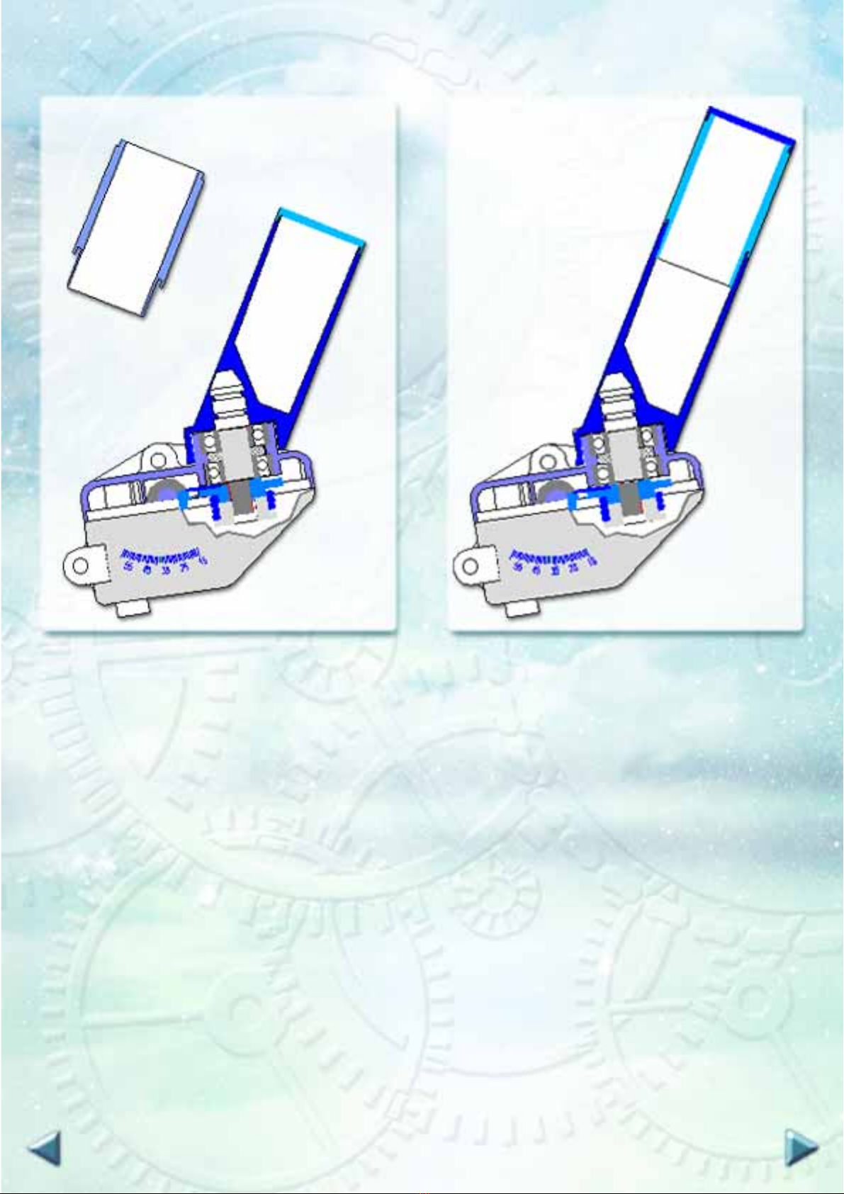
Case n. 1 If there is a picture quality improvement while bending up the dish on the Eastward sat position
and bending down on the Westward sat position unscrew slightly the bracket and rotate westwards
(clockwise) the rotor and the dish locked together (fig. 11). Tighten the screws of the supporting
bracket, then correct the dish orientation and go to the reference satellite by using the interface’s
remote control (see paragraph 7: USE OF THE REMOTE CONTROL). Find the best picture
and store the new position. Now you can operate the recalculation or you have to find each
position, check the best picture and store all positions one by one.
Case n. 2 If there is a picture quality improvement while bending up the dish on the Westward sat position
and bending down on the Eastward sat position unscrew slightly the bracket and rotate eastwards
(anticlockwise) the rotor and the dish locked together (fig. 12). Tighten the screws of the supporting
bracket, then correct the dish orientation and go to the reference satellite by using the receiver’s
remote control (see paragraph 7: USE OF THE REMOTE CONTROL). Find the best picture
and store the new position. Now you can operate the recalculation or find each position, check
the best picture and store all positions one by one.
Case n. 3 If the picture quality improves while bending the dish Up/East on the Eastward sat position and
Up/West on the Westward sat position, you should unscrew the motor support from the pole and
lower slightly the elevation of the complete system (fig. 13). Find the best picture and store the
new position. Now you can operate the recalculation or find each position, check the best picture
and store all positions one by one.
Case n. 4 If the picture quality improves while bending the dish downwards/both eastwards and westwards,
you should loosen the rotor’s fixing screws and increase slightly elevation on the bracket (fig. 14).
Find the best picture and store the new position. Now you can operate the recalculation or find
each position, check the best picture and store all positions one by one.
6.4 Disconnect the cable going to the interface from the rotor and
connect the field-strength meter. Unscrew the bolts that hold
the rotor to the main pole and then rotate EASTWARDS or
WESTWARDS both the rotor and the dish locked together
(fig. 9 - Bolt A) until you obtain the best reception quality;
tighten then again the bolts. If you cannot use a field-strength
meter, you need anyway to place a TV near the dish to check
the image definition. Connect the rotor again.


Rotor Sat HH100i-HH120i instructions manual – page 10
USE OF THE REMOTE CONTROL
7. Description of the normal buttons use
7.1 Thebuttons1÷9,thearrows“▲▲
▲▲
▲” and “▼▼
▼▼
▼”, the button “-/--” and
the buttons “EAST” and “WEST” are operative when pressed.
7.2 “1 ÷ 9” buttons allow to operate the selection of the satellites.
7.3 “▲▲
▲▲
▲” to move up to the following satellite.
7.4 “▼▼
▼▼
▼” to move down to the previous satellite.
7.5 “-/--” to use double digits numbers (10 to 49) or to return to the
single digit numbers (1 to 9).
7.6 “EAST” to rotate the dish eastwards up to the set limit.
7.7 “WEST” to rotate the dish westwards up to the set limit.
8. Description of the special buttons use
8.1 The buttons “PROG”, “RESET”, “LIMIT” and “CALC” are
operative only by pressing “FUNC”.
8.2 “FUNC+PROG” to store the satellite position.
8.3 “FUNC+RESET” to rotate automatically the rotor to the 0°
position.
8.4 “FUNC+LIMIT” to store the limits on the current position.
8.5 “FUNC+CALC” to operate the recalculation of the satellites’
positions.
8.6 “FUNC+EAST” to operate the eastwards rotation of the dish
beyond the limit.
8.7 “FUNC+WEST” to operate the westwards rotation of the dish
beyond the limit.
RCU010
▼▼
▼▼
▼
▲▲
▲▲
▲122
456
7 8 9 PROG
RESET 0 LIMIT CALC
EAST WESTFUNC -/--
FIG. 10
9. Storing a satellite position
9.1 Select the required satellite by pressing the appropriate remote control buttons (“1 ÷ 9” or “▲▲
▲▲
▲”, “▼▼
▼▼
▼”).
9.2 Rotate the dish by pressing “EAST” or “WEST” buttons until you find the required satellite.
9.3 Press “FUNC” and “PROG” buttons in sequence.
9.4 On the display will flash first the letter “F --” and then the letter “P --”.
9.5 Finally by using the remote control buttons assign a new number connected to the satellite or restate
the previous one.

Rotor Sat HH100i-HH120i instructions manual – page 11
10. Setting and storing EAST - WEST limits
10.1 The rotor is designed to rotate from 62° EAST to 62° WEST.
10.2 Two limits are set electronically at ± 65° and mechanically at ± 70° to protect the maximum rotation.
Within these limits you can though set two new electronic limits included between 5° ÷ 62° EAST and
5° ÷ 62° WEST; over these ranges the motor does not accept any memorization.
10.3 Setting the limits might become necessary if the rotor cannot perform the full rotation because of an
obstacle.
10.4 Rotate the dish by pressing the “EAST” or “WEST” buttons until it reaches the position of the new
desired EAST or WEST limit.
10.5 Press sequentially “FUNC”, “LIMIT” and “EAST” to set the EAST limit.
10.6 Press sequentially “FUNC”, “LIMIT” and “WEST” to set the WEST limit.
10.7 If the letter “L” followed by “0” or “00” will briefly appear on the display, the limit memorization has
been carried out correctly.
10.8 If not really necessary, please maintain the limits in the pre-programmed positions at ± 50°.
11. Recalculation function
Pos. nr. Satellite Posizione
1 ....................................HOT BIRD .......................................13° E
2 ....................................ASTRA 1...........................................19,2°E
3 ....................................EUTELSAT F3.................................16° E
4 ....................................EUTELSAT F2.................................10° E
5 ....................................EUTELSAT F4.................................7° E
6 ....................................SIRIUS ..............................................5° E
7 ....................................TELECOM-2C ................................3° E
8 ....................................INTELSAT 707 ................................1° W
9 ....................................TELECOM-2B,2D...........................5° W
10 ..................................TELECOM-2A ................................8° W
11 ..................................INTELSAT 705 ................................18° W
12 ..................................INTELSAT STAR............................21° W
13 ..................................INTELSAT 803 ................................27° W
14 ..................................HISPASAT........................................30° W
15 ..................................ORION..............................................37° W
16 ..................................KOPERNICUS 3 .............................23° E
17 ..................................ARABSAT 2A ..................................26° E
18 ..................................ASTRA 2...........................................28° E
19 ..................................KOPERNICUS 2 .............................28° E
20 ..................................ARABSAT 2B...................................30° E
21 ..................................TURKSAT 1B ..................................31° E
22 ..................................TURKSAT 1C ..................................42° E
23 ..................................INTELSAT 601 ................................34,5°E
24 ..................................PAS 1 .................................................45° W
25 ..................................AMOS................................................4° W
26 ..................................THOR................................................0,8° W
11.1 The rotor includes 49 satellites positions: 26 positions are pre-set, as shown on the table below, and
23 still available.

Rotor Sat HH100i-HH120i instructions manual – page 12
12.1 This function enables the rotor to return to the 0° position and to reset the inside counter. It is very
important to re-align all satellite positions that can be slightly slided eastwards or westwards from the
reference stored positions (bad picture or lost positions).
12.2 Press the remote control buttons “FUNC+RESET”.
12.3 When “0” or “00” flashes on the display then the rotor is at the 0° position.
12. Return to the 0° position of the rotor
11.2 The recalculation function automatically calculates and sets all pre-programmed satellites positions
with reference to the position of a single satellite. In other words after you have found and stored one
satellite, the recalculation procedure enables the automatic re-positioning of the other satellites inside
the rotor’s memory to a pre-defined distance, as shown on the above table.
11.3 To operate the recalculation function you must follow the steps below.
1. Select the wanted satellite by pressing the 1 ÷ 9 or the “▲▲
▲▲
▲”, “▼▼
▼▼
▼” buttons.
2. Wait until the motor stops.
2. Find the required satellite by pressing the buttons “EAST” or “WEST”.
3. Press in sequence the buttons “FUNC” and then “CALC”.
5. If the letter “U” flashes on the display, the recalculation has been carried out correctly.
13.1. To restore the initial satellites positions you have to send the rotor to the 0° position (par. 12) and
operate the recalculation function (par. 11).
13 Restoring the satellites tables

Rotor Sat HH100i-HH120i instructions manual – page 13
PROBLEMS SOLVING GUIDE
PROBLEM CAUSE REMEDY
1. The rotor does not rotate.
2. The rotor slightly exceeds the
storedsatpositions(disturbed
pictures).
3. The rotor lost all satellites
positions (no picture).
4. The rotor is blocked at the
extremes.
5. The rotor does not rotate
beyond a certain position.
6. The rotor does not focus the
sat positions even after the
recalculation procedure.
7. Extreme East/West satellites
signals are not received.
8. Central satellites signals are
not received.
9. The interface does not switch
on.
10.The interface does not accept
any instructions.
•The interface is blocked.
•The exit fuse has blown.
•Oxidisedconnectors.
•The coax cables have been inver-
ted while connecting the interface.
•Coaxial cable badly wired.
•The interface has been switched
off many times while the rotor
was moving.
•Electrical micro-interruptions.
•The rotor received a command
wrongly.
•The interface sent a wrong com-
mand.
•A limit has been set and stored on
thisposition.
•The dish pointing procedure was
not carried out correctly.
•Wrong setting ofrotor’selevation
angle.
•The mains fuse has blown.
•Remote control batteries are mis-
sing or discharged.
•Disconnect the interface from
the mains for 30 seconds.
•Substitute fuse by authorised
personnel.
•Substituteconnectors.
•Connect correctly the coax
cable.
•Check F connection on the
cable (fig. 4).
•Send re-alignment command
(par. 12).
•Findasatelliteandoperatethe
re-calculationfunction(par.11),
or store again all sat positions
one by one.
•Removethelimitsandstorethem
againinmoreappropriateposi-
tions (par. 10).
•Repeat dish pointing procedure
followingcarefullytheinstruc-
tionsonpage7-parag.6“DISH
POINTING”.
•Repeatmorecarefullythe pro-
cedures on page 7, paragraphs
4, 5, 6.
•Substitute fuse by authorised
personnel.
•Insert batteries.
•Substitute batteries.
WARNING! NEVER DISCONNECT THE INTERFACE FROM THE MAINS WHILE THE MOTOR
IS MOVING TO AVOID THE LOSS OF ALIGNMENT.

Rotor Sat HH100i-HH120i instructions manual – page 14
This rotor is produced and tested by our laboratory with extreme care and carries a warranty for 12 months
from purchase date.
A copy of the shop receipt or the invoice represent the warranty document and must be sent together with
the set when returned. This warranty covers all production defects and working faults, but excludes all
damages caused by drops, incorrect use or external oxidations due to incorrect installation. Any repair
made by unauthorised personnel will automatically cancel this warranty.
WARRANTY CONDITIONS

For further information and advices about installation and uses contact
YOUR LOCAL DEALER
or
STAB Technical Office:
Via Seminiato, 79 - 44031 AMBROGIO (FERRARA) - ITALY
Local time 8.00 to 12.00 a.m. and 1.30 to 5.30 p.m. (MIDDLE EUROPE time)
Phone +39-0532-830739 Fax +39-0532-830609
Rotor Sat HH100i-HH120i instructions manual – page 15
www.stab-italia.com
e-mail: [email protected]
PRINT
BACK TO THE CONTENTS TABLE
This manual suits for next models
1
Table of contents
Other Stab Engine manuals


