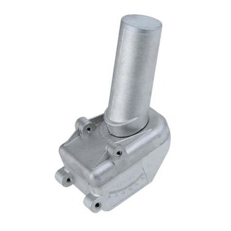
Stab HH100 User manual

Instructions manual
Bedienungsanleitung
Manuale istruzioni
Mode d'emploi
Manual de istrucciones
ROTOR SAT HH100 - HH120
SAT FINDER
®
®
ROTOR SAT DIVISION
ROTOR SAT DIVISION
www.stab-italia.com

F
GB
E
DEARCUSTOMER,
Congratulations!
Youarenowtheownerof STABROTORSAT.
This is the sat motor developed in cooperation with EUTELSAT in order to define the
®
DiSEqC1.2 standardincludingthenewUSALSsystemwithSATFINDER.
ROTOR SAT DIVISION
SEHRGEEHRTERKUNDE!
SEHRGEEHRTEKUNDIN!
HerzlichenGlückwunschzumKaufdesSTABROTORSAT.
Dieses Produkt wurde in Zusammenarbeit mit EUTELSAT für die Realisierung des
DiSEqC1.2StandardentwickeltundenthaltetdasneueUSALS-SystemmitSATFINDER.
D
I
EGREGIOCLIENTE,
Congratulazioni.Leiorapossiedeil ROTORSATdellaSTAB.
Questo è il primo rotore sviluppato in collaborazione con Eutelsat per la realizzazione del
®
protocollo DiSEqC1.2 edincludeilnuovosistemaUSALSconSATFINDER.
CHER CLIENT,
Félicitations!Vousêtesdétenteurd’unROTORSATSTAB.
C’est le premier moteur réalisé par STAB en collaboration avec EUTELSAT ayant permis
®
la création du protocole de communication DiSEqC1.2 qui contient le nouveau système
USALSavecSATFINDER.
ESTIMADO CLIENTE,
¡Felicidades!UstedesahoraeldueñodeROTORSATparaSatélitedeSTAB.
Éste es el motor de satélite desarrollado en cooperación con EUTELSAT para definir la
®
normaDiSEqC1.2 . IncluyetambiénelnuevosistemaUSALSconSATFINDER.
2

Note your data
Annota i tuoi dati
Anote sus datos
Annotez vos coordonnées.
Schreiben Sie Ihren Daten darauf.
3
www.stab-italia.com/maps.php
Latitude
Longitude
Dish elevation
In order to install the motor in USALS mode as well as in
DiSEqC1.2 mode you need to know the following data of the
installation place: Latitude, Longitude and dish elevation.
You could make out these data from website www.stab-
italia.com/maps.php orfromthemapsattheendofthismanual.
Um das Rotor in USALS oder DiSEqC1.2 Modalität zu
installieren, sind die Daten des Breitengrads, des
Längengrads und der Antennenelevation notwendig. Sie
werden diese Daten aus www.stab-italia.com/maps.php oder
ausderKartenamEndedieserAnleitungerhaltenkönnen.
Per l'installazione del rotore in modalità USALS o DiSEqC1.2
sono necessari i dati di: Latitudine, Longitudine, Elevazione
antenna del luogo di installazione. Potete ricavare questi dati
dalsito www.stab-italia.com/maps.phpo dallemappe allafine di
questomanuale.
Pour installer votre moteur en modalité USALS aussi qu'en
modalité DiSEqC1.2, vous aurez nécessité des coordonnés
suivantes: Latitude, Longitude et Elévation de l'antenne.
Vous pourriez obtenir ces donnés du site Internet www.stab-
italia.com/maps.php oudescartesàlafindecelivret.
Para la instalación del rotor en modo de USALS o de
DiSEqC1.2, son necesarios los datos de la Latitud, Longitud,
Elevación de la antena del lugar de instalación. Usted puede
obtener estos datos en el sitio web www.stab-
italia.com/maps.phpoenlasmapasalfinaldeestemanual.
>Warning
>Technical data
>Assembly
>USALS info
>USALS installation
>DiSEqC1.2 installation
>ADJUSTMENTS
>Accessories
>Problems
>MAPS
>Warranty
Coordinates
INDEX
4
6
8
10
13
22
32
38
41
44
58
!

4
GB
WARNING
®®
>
ToconnectthemotorwithoutinterfaceitisnecessarythatyourreceiverincludesDiSEqC1.2 orUSALS protocol.
>Pleasereadcarefullythisinstructionsmanualbeforeinstallingandusingit.
>Donotconnectthistooltoanyotherdevicenotspecificallydescribedinthishandbook.
>Forthemovementandmemorizationcommands,seethereceiver’sinstructionsmanual.
>
>
>
>
>
>
>
>
>
>
Onlyaspecialistcanguaranteeacorrectmechanicalinstallationwhichwillavoiddamageorseriousinjury.
Themotormustnotbemountedupside-down.
For mounting, all the screws and nuts contained in the kit must be used. The absence of one screw or nut may
causeinstabilityorthefalloftheequipment.
The motor has been tested for resistance in wind conditions of 140 Km/h with a dish of 120 cm, so care must be
taken in choosing the supporting pole and its anchorage. If possible, installation should be carried out in a place
shelteredfromwind(rooftopsareneveradvisable).
Theuseofdisheswithalargerdiameterthanthatindicatedinthespecificationsforeachmotorisstrictlyprohibited.
Themotor,beingamechanicalrotatinginstrument,mustbeinstalledoutofreachofpeople.
Themotormustnotbeusedforpurposesotherthanthoseindicatedbythemanufacturer.
Themotor hasbeen designedtobesuppliedby asat receiveror bya positioner;anyothertype ofsupply isstrictly
prohibitedandmaycausedamageorseriousinjury.
Some receivers have an anti-disturbance system linked to the body of the connector F. This may provoke a slight
electricshocknotdangerousfor theuser.Inparticularconditions (e.g.onaroofor onastaircase)it maycausefalls
orinjuries.Eachtimethemotorishandledthereceivermustbedisconnectedfromtheoutlet.
Neverswitchoffthereceiverwhilethemotorismovingtoavoidthelossofalignment.
WARNHINWEISE
®®
>Um den Motor ohne Schnittstelle anschließen zu können, muss Ihr Receiver über DiSEqC1.2 oder das USALS
Protokollverfügen.
>BittelesendieseBedienungsanleitungVORderInstallationundderInbetriebnahmesorgfältigdurch.
>Bitte beziehen Sie sich auf die Bedienungsanleitung Ihres Receivers um die Befehle für die Drehsteuerung und
AbspeicherungderPositionenherauszufinden.
>Nur Fachpersonal kann eine korrekte mechanische Installation sicherstellen, die Schäden bzw. Verletzungen
verhindert.
>EineInstallationdesMotorsinumgekehrterAusrichtungistverboten.
>Fürdie Installation müssen allemitgelieferten Schrauben und Mutternverwendet werden. DasNichtverwendennur
einerSchraubeoderMutterkanndieStabilitätdesSystemsgefährdenundzumangelhafterBefestigungführen.
>Der Motor wurde auf Windwiderstand bis 140 km/h getestet, mit einer Satellitenantenne mit 120 cm Durchmesser.
Dementsprechend muss ein entsprechender Stützmast verwendet werden, der ausreichend stabil fixiert wird. Falls
möglich,sollteeinwindgeschützterAufstellungsortgewähltwerden(Dachmontagewirdnichtempfohlen).
>Die Verwendung von Satellitenantennen mit einem größeren als für jeden Motor angegebenen Durchmesser ist
strengstensverboten.
>Der Motor ist ein mechanischer, beweglicher Bauteil und muss daher außerhalb der Reichweite anderer Personen
installiertwerden.
>DerMotordarfnurfürdievondemHerstellerangegebenenZweckeeingesetztwerden.
>Der Motor wurde für Stromversorgung über einen Satellitenreceiver oder Satellitenpositioner entwickelt. Jede
andereArtderStromzufuhriststrengstensverbotenundkannzuSchädenoderschwerenVerletzungenführen.
>Einige Receiver besitzen ein System zur Störungsminimierung, das mit dem Gehäuse des F-Steckers verbunden
ist. Dadurch kein ein leichter elektrischer Schlag ausgelöst werden, der für denAnwender absolut ungefährlich ist.
Unter besonderen Umständen (z.B. auf dem Dach oder auf einer Stiege) kann dieser Schlag aber einen Sturz oder
Verletzungenverursachen.BeijederArbeitamMotormussderReceiverdahervomStromnetzgetrenntwerden.
>SchaltenSieniemals denReceiveraus während derMotorsich bewegt umdiegespeicherten Einstellungen
nichtzuverlieren.
D
!!
!!
®
®
®
The DiSEqC1.2 system is a trademark of EUTELSAT.
®
The USALS system is a trademark of STAB - patent nr 002249506
The designs and technical data may be modified without warning and remain the property of STAB.
RoHSRoHS
COMPLIANT
2002/95/EC
with
SAT FINDER

I
ATTENTION
AVVERTENZE
®
>PerpotercollegareilmotoreènecessariocheilricevitoresiaconformeallostandardDiSEqC1.2 oUSALS .
>Perl'installazioneel'usoLapreghiamodileggereconattenzionequestomanuale.
>Pericomandidimovimentoedimemorizzazioneverificareillibrettod'istruzionedelricevitore.
>
>
>
>
>
>
>
>
>
>
®
Solounospecialistavipuògarantireunacorrettainstallazionemeccanica,chepossaevitaredannioinfortunigravi.
Ilmotorenonpuòesseremontatocapovolto.
Perilmontaggiosidevonoimpiegaretuttelevitiedadicontenutinelkit.Lamancanzadiundadoovitepuòesserecausa
d'instabilitàocadutadelsistema.
Il motore è stato collaudato per resistere in condizioni di vento pari a 140 Km/h con un'antenna da 120 cm, pertanto si
dovrà avere molta cura nella scelta del palo di sostegno e del suo ancoraggio. Se possibile eseguire l'installazione in
luogoriparatodalvento(itettidellecasesonosconsigliati).
L'impiegodidischicondiametrosuperioreaquelloindicatonellespecifichediognimotoreèseveramenteproibito.
Il motore,essendounorganomeccanicocheruota,deveessereinstallatofuoridellaportatadellepersone.
Ilmotorenonpuòessereutilizzatoperimpieghidiversidaquelliindicatidalproduttore.
Il motore è stato progettato per essere alimentato da un ricevitore sat o da un posizionatore; qualsiasi altro sistema di
alimentazioneèseveramenteproibitoepuòcausaredannioinfortunigravi.
Alcuniricevitori hanno ilsistema antidisturbo collegatoalla massa delconnettore F.Questo può provocareuna leggera
scossa elettrica non pericolosa per l'utente. In condizioni particolari (es. su un tetto o una scala) può essere causa di
caduteoinfortuni.Ognivoltachesiintervienesulmotoresidevescollegareilricevitoredallapresadicorrente.
Non scollegare mai il ricevitore dalla presa di corrente mentre il motore è in movimento. Si potrebbe perdere
l'allineamentodeisatelliti.
®®
>
Pour utiliser le moteur sans interface, il est nécessaire que votre récepteur intègre les protocoles DiSEqC1.2 ou USALS .
>Pour l'installation,lire attentivementcemanuel.
>Pourlescommandesdemouvementet demémorisation, seconformer aumanuel durécepteur.
>
>
>
>
>
>
>
>
>
>
Seul un spécialiste est en mesure de garantir une installation mécanique permettant d'éviter des dommages, des risques et
desproblèmesimportants.
Lemoteurnedoitenaucun casêtremontétête bêche.
Pour un montage conforme et sans risque toutes les pièces (boulons, rondelles et écrous) fournis dans le kit de montage
doiventêtreutilisés.Toutoublipeutêtrelacaused'instabilitéou dechutedusystème.
LesmoteursHH100etHH120ont étéconçuspourtracterrespectivementdes antennesde1mètreet1.2 mètrepardes vents
de 140 kilomètres/heure, nous vous demandons, d'être très attentif au choix: du support de montage (extrême robustesse);
delasolidité,delarésistancedupointd'encrage,ainsique dela qualitédesboulonsutilisés;del'emplacementdel'installation
(leplusàl'abripossibled'importantesrafalesdevent).L'installationsurlestoitsfragiles estdéconseillée.
L'usaged'antennesdedimensionssupérieuresà cellesindiquées danslesspécificationstechniques estprohibé.
Lemoteurétantunepièce enmouvement,ildoitimpérativementêtreinstalléhorsdelaportéed'êtresvivants.
Lesmoteursnedoiventenaucun casêtre utiliséspourd'autresusages queceux prévusparleproducteur.
Le moteur a été développépour être alimenté par unrécepteur satellite ou un positionneur, tout autre système d'alimentation
estformellementinterditetpeutcréer degraves dommages.
Certains récepteurs satellites ont un système anti-parasites connecté à la masse du connecteur F. Ceci peut provoquer de
légères secousses électriques sans danger pour l'utilisateur. Attention des chutes peuvent survenir à cause de l'utilisation
d'échelle, ou par le fait de se trouver sur un toit ou dans des endroits dangereux. C'est pourquoi nous vous conseillons, pour
chaqueinterventiondirectesurlemoteur,hors installation,dedéconnecterlesrécepteurssatellitesdesprisesdecourant.
Il est important de ne jamais éteindre le récepteur pendant le déplacement du rotor d'un satellite à l'autre pour éviter
laperted'alignementdespositionsmemoriseés.
F
ADVERTENCIAS
E
®®
>
ParaconectarelmotorsinunainterfazesnecesarioquesureceptorincluyaDiSEqC1.2 oelprotocoloUSALS .
>Porfavorleacuidadosamenteelmanualdeinstruccionesantesdeinstalaryusarestemotor.
>Paralasórdenesdemovimientoydememorización,veaelmanualdeinstruccionesdelreceptor.
>Sólounespecialistapuedegarantizarleunainstalaciónmecánicacorrectaqueevitarádañosolesionesserias.
>Elmotornodebemontarsenuncaalrevés.
>En el montaje, deben usarse todos los tornillos y tuercas contenidas en el equipo. La ausencia de un tornillo o tuerca
puedecausarinestabilidadoelfallodelequipo.
>El motor se ha probado para resistir unas condiciones de viento de 140 Km/h con un plato de 120 cm, por eso debe
tenerelcuidadodeescogerunmástildeapoyoysu anclaje.Siposible,la instalacióndebellevarsea caboenunlugar
albergadodelviento(lasazoteasnuncasonaconsejables).
>Seprohíbeestrictamenteelusodeplatosconundiámetromásgrandedelosindicadosenlasespecificaciones.
>Elmotor,yaqueesuninstrumentoconmovimientomecánico,debeinstalarsefueradealcancedelaspersonas.
>Elmotornodebeusarseparaotrospropósitosqueaquellosindicadosporelproductor.
>El motor se ha diseñado para ser utilizado con un receptor de satélite o por un posicionador, cualquier otro tipo de
suministroestáprohibidoestrictamenteypuedecausardañosolesionesserias.
>Algunos receptores tienen un sistema de anti-perturbación unido al cuerpo del conector F. Esto puede provocar un
choque eléctrico ligero no peligroso para el usuario. En condiciones particulares (por ejemplo en un tejado o en una
escalera) puede causar caídas o lesiones. Cada vez que se tenga que manipular el motor el receptor debe ser
desconectadodelatomadecorriente.
>Nuncaapagueelreceptormientraselmotorestáenmovimiento paraevitarlapérdidadealineamento.
!!
!!
!!
5

Communication protocol
Kommunikationsprotokoll
Protocollo di comunicazione
Protocole de communication
Protocolo de Comunicación
Maximum dish diameter and weight
Max. Antennendurchmesser / Antennengewicht
Diametro e peso massimo antenna
Diamètre et poids maximum d'antenne
Diámetro y peso máximo del plato
Diameter of support pole
Durchmesser des Stützmasten
Diametro palo di supporto
Diamètre mât de support
Diámetro del palo de soporte
Dish support length and diameter
Länge und Durchmesser der Antennenstütze
Lunghezza e diametro del supporto antenna
Longueur et diamètre du support mobile
Longitud y diámetro del soporte del plato
Rotation angle and speed
Rotationswinkel und Rotationsgeschwindigkeit
Angolo e velocità di rotazione
Angle et vitesse de rotation
Ángulo y velocidad de rotación
Operating power supply
Betriebsstromversorgung
Tensione di lavoro
Alimentation
Tensión de alimentación
Consumption in stand-by / operating / starting mode (max)
Stromverbrauch Standby / Betrieb / Bewegungsstart (max)
Assorbimento in stand-by / in movimento / massimo
Consommation en stand-by / pendant le mouvement / max
Consumo en modo de reposo / en movimiento / máximo
Operating temperature / Maximum relative humidity
Betriebstemperatur / Max. rel. Luftfeuchtigkeit
Temperatura di lavoro / Umidità relativa massima
Température d'utilisation / Humidité maximum
Temperatura de trabajo / Humedad máxima relativa
®
DiSEqC1.2 Level
100 cm / 12 kg
ø (50 to 76) mm
125 mm / ø 54 mm
±65°
1,8°/s (18V) 1,2°/s (13V)
13/18 Vdc
30 mA
190 mA
350 mA
-40°C +80°C
100%
®
DiSEqC1.2 Level
120 cm / 17 kg
ø (50 to 76) mm
180 mm / ø 54 mm
±65°
0,7°/s (18V) 0,4°/s (13V)
13/18 Vdc
30 mA
190 mA
350 mA
-40°C +80°C
100%
HH100 HH120
TECHNICAL DATA
6
HH120
HH100

Programmable positions
®
Posizioni pre-programmate (DiSEqC1.2 )
®
Positions programmables (DiSEqC1.2 )
®
(DiSEqC1.2 )
®
Preset positions (DiSEqC1.2 )
®
Posizioni pre-programmate (DiSEqC1.2 )
®
Positions pré-programmées (DiSEqC1.2 )
®
(DiSEqC1.2 )
Programmable positions
®
Posizioni pre-programmate ( )
®
Positions programmables ( )
®
()
Connection / connectors
Type de connexion / Connecteurs
Mechanical limits
Limti meccanici
Limites mécaniques
Programmable electrical limits
Limiti elettronici programmabili
Limites électroniques programmables
Fine rotation
Rotazione fine
Rotation lente
Inclination of the rotor on the pole
Inclinazione del rotore sul palo
Inclinaison
Rotor weight
Poids du rotor
Accessories
Zubehör
Accessori
Accessoires
Accessorios
®
(DiSEqC1.2 ) ®
Programmierbare Positionen (DiSEqC1.2 )
Posiciones programables
®
Voreingestellte Positionen (DiSEqC1.2 )
Posiciones preprogramadas
®
(USALS ) ®
Programmierbare Positionen (USALS )
USALS
USALS
Posiciones programables USALS
Anschlussart / Anschlüsse
Collegamento / connettori
Conexión / Conectores
Mechanische Begrenzung
Límites mecánicos
Programmierbare elektrische Begrenzung
Límites Eléctricos Programables
Feinbewegung
Rotación fina
Neigung des Rotors am Mast
Inclinación del rotor respecto al palo
Rotorgewicht
Peso rotore
Peso del rotor
49 satellites
28 satellites
no limits
Coaxial cable
F type
±70°
from 5° to 65°
by impulses of 0,1°
from 15° to 70°
3 kg
PR01
49 satellites
28 satellites
no limits
Coaxial cable
F type
±70°
from 5° to 65°
by impulses of 0,1°
from 15° to 70°
3,2 kg
AN01
DS01
7
TECHNICAL DATA
HH100 HH120

Bracket for anchoring the pole
Staffa per ancoraggio al palo
Support de fixation au mât
Klammer für den Masten
Abrazadera para fijarlo al mástil
F Connectors
F-Anschlüsse
Connettori F
Conectores F
Connecteurs F
U Bolts
U-Bolzen
Cavallotti
Cavaliers
Espárrogos
Clamps
Klemmschraube
Morse
Mors
Pinzas
M8 Screws
M8 Schrauben
Tornillos de M8
Viti M8
Boulons M8
M8 Nuts
M8 Muttern
Tuercas de M8
Dadi M8
Ecrous M8
AB
C
E
D
F
ø 8mm washers
Rondelle ø 8 mm
Rondelles ø 8mm
ø 8mm Unterlegscheiben
Arandelas de ø 8mm
Connector covers
Anschlussabdeckung
Copriconnettori
Couvres connecteurs
Cubiertas para conectores
H
ASSEMBLY
8
G

L= 30 ÷ 60 m
18 Ω/km (max)
10 Ω/km (max)
Ø=1,02mm Ø=1,13mm
22 Ω/km (max) 18 Ω/km (max)
8mm
15mm
3mm
A
B
C
D
E
G
H
L= < 30 m
Characteristics of the coaxial cable
Eigenschaften des Koaxialkabels
Caratteristiche del cavo cossiale
Caractéristiques du câble coaxial
Características del cable coaxial
F
ASSEMBLY
9

®
The USALS system (Universal Satellite Automatic Location System) is a calculation system processed by STAB
which enables the receiver to calculate the position of all satellites in orbit with a precision lower than 1 meter with
reference to the place of installation. All this in a completely automatic mode and with no specific technical
knowledgerequired,eitherduringinstallationoruse.
(SATFINDER)
Models HH100 and HH120 implement a sound system in order to help in pointing the satellite. This system
consistsof an acousticdevice(beep)with4soundintensitylevels:
st
1 beeplevel:youareintherotorpointingmode.
nd
2 beeplevel:thesignaloftheselectedsatelliteiscaptured.
rd
3 beeplevel:thesignalqualityisincludedbetween70%and90%.
th
4 beeplevel:thesignalqualityisupto90%(itisnotalwayspossibletoreachthislevel).
Howtorecognizeifyourreceiverisincompliancewith“USALS”standard:
>Thereceiver boxmust carrythe USALSlogo(A)or(B). USALSlogo (B)indicates thatthe soundpointingsystemis
available .
>In“Motorsetting”menutheremustbethe“USALS”mode.
GB
USALS INFORMATIONS
USALS INFORMATIONEN
D
®
Was ist nun aber dieses USALS -System genau? Die Abkürzung steht für "Universal SatelliteAutomatic Location
System" und ist ein von STAB entwickeltes Berechnungsprogramm, das unentgeltlich allen Herstellern von
Satellitenreceivern und PC-Karten zur Verfügung gestellt wird. Damit ist es möglich, die Positionen aller Satelliten
mit einer Genauigkeit von weniger als 1 Meter Abweichung in Bezug auf den Installationsort zu berechnen. Der
gesamte Vorgang wird automatisch durchgeführt und erfordert kein besonderes Fachwissen seitens des
Anwenders wederbeiderInstallationnochbeimBetrieb.
(SATFINDER)
Die HH100 und HH120 Modelle enthalten darüber ein Tonsystem, um das Satellitenzeigen zu erleichtern.
DiesesSystembestehetineinemTonsignal(Beep)mit4Stärkezustände:
ErsterBeepzustand:manbefindetsichimMotorszeigenmenü.
ZweiterBeepzustand:dasSignaldesausgewähltenSatellitenwirdempfangen.
DritterBeepzustand:dieSignalsqualitätistzwichen70%und90%enthaltet.
VierterBeepzustand:dieSignalsqualitätisthohëreals90%(nichtimmeristesmöglich,diesenZustandzu
erreichen).
Wieerkanntman,obeinReceiverdenUSALS-Standardunterstützt?
>Auf dem Receiver muß sich das USALS-Logo (A) oder (B) befinden. Das USALS (B) Logo zeigt, daß das
TonsystemfürSatellitenzeichenverfügbarist .
>ImMenüpunkt„Motorsteuerung“mußderUnterpunkt„USALS“vorhandensein.
A)
B) NEW USALS LOGO
SAT FINDER FUNCTION INCLUDED
CLASSIC USALS LOGO
USALS INFO
10

INFORMAZIONI SUL SISTEMA USALS
I
®
Il sistema USALS (Universal Satellite Automatic Location System) è un sistema di calcolo elaborato da STAB che
permettealricevitoredicalcolarelaposizionedi tuttiisatellitiinorbitaconlaprecisioneinferiorea1 metrorispettoal
luogod’installazione.Tuttoquesto in modoautomatico,senzarichiedere conoscenze tecniche all’utente sia in fase
d’installazione,cheinfased’utilizzo.
I modelli HH100 e HH120 implementano inoltre un sistema sonoro per aiutare il puntamento del satellite. Il
sistemaconsisteinunsegnaleacustico(beep)con4livellidiintensità:
1°livellobeep:indicachecitrovainmodalitàdipuntamentodelrotore.
2°livellobeep:vieneagganciatoilsegnaledelsatelliteselezionato.
3°livellobeep:qualitàdelsegnalecompresatra70%e90%.
4°livellobeep:qualitàdelsegnalesuperioreal90%(nonsempreèpossibileraggiungerequestolivello).
®
Comecapireseilvostroricevitoreèconformeallostandard“USALS “:
>SulricevitoredeveesserepresenteillogoUSALS (A)oppure(B).Illogo USALS (B)indicacheèpresenteancheil
sistemaacusticodipuntamento(SATFINDER). ®
>Nelmenu“Motorsetting”deveesserepresentelamodalità“USALS ”
INFORMATIONS GENERALES CONCERNANT L'USALS
F
®
Le système ''USALS '' (Universal Satellite Automatic Location System) c'est un logiciel de calcul mis au point par
STAB qui permet au récepteur de calculer les positions des satellites en orbite géostationnaire avec une précision
inférieureà 1mètre parrapport aulieud'installation.Tout cecien modeautomatique sansbesoin deconnaissances
techniquesdel'utilisateur,quecesoitenphased'installationoud'utilisation.
®
Commentreconnaîtrequevotrerécepteurestconformeaustandard''USALS '':
>
(SATFINDER)
>
SurlesmodèlesHH100etHH120unsystèmeacoustiqueaidel'utilisateuraupointagedusatellite.
Ce système se constitue d'un dispositif acoustique (beep) avec 4 niveaux d'intensité :
ère
1 niveau beep : il indique qu'on se trouve en modalité de pointage du moteur.
ème
2 niveau beep : le signal du satellite sélectionné a été accroché.
ème
3 niveau beep : la qualité du signal est comprise entre 70% et 90%.
ème
4 niveaubeep:laqualitédusignalestsupérieureau90%(cen'estpastoujourspossibled'atteindreace
niveau).
Surleboîtier durécepteurdoitfigurerlelogo«USALS»(A)ou(B).Lelogo USALS(B)indique quedanscemoteur
lesystèmeacoustiquedepointageestdisponible .
Danslemenu«moded'utilisation»doitfigurerlemot«USALS».
LA INFORMACION DE USALS
E
®
El sistema USALS (Universal Satellite Automatic Location System) es un sistema que ha diseñado STAB para
procesar el cálculo que permite al receptor que calcule la posición de todos los satélites en la órbita con una
precisión menor de 1 metro a partir de las coordenadas de referencia del lugar de la instalación. Todos esto de un
modocompletamenteautomático ysinrequerirningúnconocimiento técnicoespecífico,durantesuinstalación osu
uso.
Ademas, los modelos HH100 y HH120 incluyen un sistema de sonido para ayudar el puntamento del satélite.
Elsistemaconstadeunaseñalacústica(bip)con4nivelesdeintensidad:
1°nivelpitido:indicaqueestamosenmododepuntamentodelrotor.
2ºnivelpitido:hasidoenganchadalaseñaldelsatélite.
3°nivelpitido:calidaddelaseñalincluidaentre70%y90%.
4°nivelpitido:calidaddelaseñalsuperioral90%(nosiempreesposiblellegaraestenivel).
®
Cómoreconocersisureceptoresconformealanormade"USALS ":
Enlacajadebehaberellogotipo"USALS(A)o(B). EllogotipodeUSALS(B)indicaqueelmotorincluyeelsistema
acústicodelpuntamento(SATFINDER). ®
Enelmenúde"AjustesdelMotor"debehaberelmodo "USALS ".
>
>
USALS INFO
11

12
USALS INFO
I
F
E
GB
D
Exampleof calculationof the satellitesposition with referenceto Romeperformedautomatically bya
®
receiverimplementedwithUSALS program:
Beispiel für die Berechnung der Satellitenpositionen mit Aufstellungsort Roma automatische
®
DurchführungbeieinemReceivermitUSALS -Unterstützung:
Esempiodicalcolo della posizionedei satellitirispetto allacittà diRoma eseguitoin automaticoda un
®
ricevitoreconilprogramma“USALS ”.
Exemple des calculs de la position des satellites par rapport à la ville de Roma, exécutés en
®
automatiqueparunrécepteurincluantleprogramme''USALS ’'.
Ejemplo de cálculo de la posición de los satélites con referencia a la situación de Roma realizada
®
automáticamenteporunreceptorllevadaacaboconelprogramade“USALS ”:
Astra
19,2° E
Hot Bird
13,0° E
Hispasat
30,0° W
SOUTH =
Longitude =
12,5° E
Astra 19,2°E
HotBird 13°E
Hispasat 30°W
Satellite
+ 7,5°
+ 0,6°
- 46,9°
++
--
USALS
automatic calculation
ROMA
Rome:Latitude 41,9°N
Longitude 12,5°
Coordinates Rotation angle

USALS installation
USALS
If your receiver is in compliance with USALS standard, you can start installation as follows. The
required data are your geographical coordinates and the dish elevation value you had previously
made out (see page 3).
Falls Ihr Receiver USALS-normgerecht ist, können Sie die Installation wie weiter einführen. Die
nötigen Daten sind Ihre geographischen Koordinaten und der Antennenelevationswert, den Sie
vorhererhaltethaben(sieheSeite3).
Si votre récepteur est conforme au standard USALS, vous porriez commencer l'installation de façon
suivante. Les données nécessaires sont les coordonnées géographiques et la valeur d'élévation de
l'antennequevousaurezobtenuesprécédemment(voirpage3).
Sisureceptores conforme alestándar de USALS,puede comenzar conla instalación en lasiguiente
manera. Los datos necesarios son sus coordenadas geográficas y la elevación de la antena que ha
obtenidopreviamente(veapagina3).
Se il vostro ricevitore è conforme allo standard USALS potete iniziare l'installazione nel modo
seguente. I dati necessari sono le vostre coordinate geografiche e l'elevazione dell'antenna che
avetericavatoprecedentemente(pag.3).
I
F
E
GB
D
®
13

USALS
1
F
GB
E
D
I
>Choose a position from where the dish can see the SOUTH without any impediments or
obstructions.Buildings,trees,water-pipesetc.canblockpartiallyorcompletelythesatreception.
>Inordertoobtainacorrectpointingofthesatellites,allsystemsmustbeinaperfectplumbline.
>Wählen Sie eine Stelle aus von der aus der Spiegel uneingeschränkte Sicht nach SÜDEN hat.
Gebäude jeder Art, Bäume, Wasser- oder sonstige Rohre etc. können den Satellitenempfang
teilweiseoderganzbehindern.
>UmeinekorrekteAusrichtungaufdieSatellitensicherzustellen,müssenalle SystemegenauimLot
aufgestelltsein.
>Choisir un endroit où le Sud est complètement dégagé. Aucun édifice, arbre, poteau, etc, ne doit
obstruerd’aucunemanièrelaréceptiondessignauxémisparlessatellites.
>Afin d'obtenir un pointage parfait vers tous les satellites, votre mât de support doit être parfaitement
d’aplomb.
>
>
Escoger una posición dónde el plato pueda ver el SUR sin ningún impedimento u obstrucción. Los
edificios, los árboles, las tuberías de agua, etc. pueden bloquear parcial o completamente la
recepcióndelsatélite.
Para obtener una alineación correcta a los satélites, el palo de soporte debe estar en una línea de
plomadaperfecta.
14
>Scegliere una posizione dove l'antenna possa avere una visuale libera verso SUD. Edifici, alberi,
grondaie,ecc. Impedisconoparzialmenteototalmentelaricezionedelsegnalesat.
>Fissareilpalodisostegno(ø50÷76mm)inposizioneperfettamenteverticale.
Minimum height to avoid vibration
Mindesthöhe zur Vermeidung von Vibrationen
Altezza più bassa possibile per evitare vibrazioni
Hauteur minimale pour éviter les vibrations
Altura mínima para evitar la vibración
Plumb line
25 m
c
Ø= 50÷76 mm

USALS
2
F
GB
E
D
I
Fix the motor to the supporting pole tightening the brackets by hand uniformly. Turn all system to
the SOUTH with the help of a compass or following the information data provided by website
www.stab-italia.com/maps.php
Befestigen Sie den Rotor am Masten festziehend die Klammer zu Hand gleichförmig. Drehen Sie
das Antenne-Motor System nach Süden mit Hilfe von einem Kompaß oder der Information aus
www.stab-italia.com/maps.php
Fissare il rotore al palo di sostegno stringendo a mano in modo uniforme le morse di fissaggio.
Ruotare tutto il sistema in direzione SUD, aiutandosi o con una bussola oppure con l'indicazione
fornitadalsito:www.stab-italia.com/maps.php
Fixez le moteur au mât de support serrant uniformément les écrous à main. Tournez l'ensemble
moteur/parabole vers le sud à l'aide d'une boussole ou suivant les indications fournies par le site
www.stab-italia.com/maps.php
Fije el rotor al palo de apoyo y apriete a mano las abrazaderas de fijación de manera uniforme.
Mueva el conjunto de plato y motor hacia el SUR, con la ayuda de una brújula o con la indicación
proporcionada por el sitio: www.stab-italia.com/maps.php
SOUTH
www.stab-italia.com/maps.php
15
SOUTH
SOUTH
NOTE:
For installations in the southern hemisphere, point the rotor northward.
Für Installationen in der südlichen Hemisphäre, richten Sie den Rotor nach Norden.
Pour les installations dans l'hémisphère sud, pointer le rotor vers le nord.
Per l'installazione nell'emisfero sud puntare il rotore verso nord.
Para la instalación en el hemisferio sur punte el rotor hacia el norte.

3
F
GB
E
D
I
FIXING SCREWS
BEFESTIGUNGSSCHRAUBEN
VITI DI FISSAGGIO
BOULON DE FIXATION
TORNILLOS DE FIXACIÓN
AdjusttherotorinclinationtoyourLatitudeandtightenthefixingscrews.
PassenSiedieRotorneigunganIhrenLängengradanundziehenSiedieSchraubenfest.
Regolarel’inclinazionedelrotoreconilvaloredellavostraLatitudineestringerelevitidifissaggio.
Réglezl'inclinaisondurotorselonlaLatitudedelieud’installationetserrezlesboulonsdefixation.
AjustelainclinacióndelrotorasuLatitudyaprietelostornillosdefijaciónconunllavede13mm.
Latitude
16
USALS
13 mm

USALS
4
F
GB
E
D
I
>Fixthedishtotherotor’santennasupportwithouttighteningdefinitivelythescrews.
>Alignperfectlytherotor’stubeindicator tothedishaxisandtightenthescrews.
>Befestigen Sie die Antenne an der Antennenstütze des Rotors ohne die Schrauben ganz fest zu
ziehen.
>Richten Sie die Stützauflage des Rotors exakt auf die Antenneachse aus und ziehen Sie die
Schraubenfest.
>Fissarelaparabolaaltubodelrotoresenzastringeredefinitivamentelamorsadifissaggioparabola.
>Allineare perfettamente l’indicatore del perno rotore con l’asse dell’antenna e stringere la morsa di
fissaggioparabola.
>Fixez la parabole sur la partie mobile du rotor (Support d’antenne), sans serrer définitivement les
écrous.
>Alignez parfaitement l'indicateur de centrage avec l’axe de la parabole et serrez définitivement les
écrous.
>Fijeelplatoalsoportedelaantenaenelrotorsinapretarlostornillosdefinitivamente.
>Alineeperfectamentelaescaladelrotoralejedelplatoyaprietelostornillos.
INDICATOR
STÜTZAUFLANGE
INDICATORE
INDICATEUR
INDICADOR
17

AligntheDishElevationandtightenthefixingscrews.
F
GB
E
D
I
PassenSiedieAntennenelevationanundziehenSiedieSchraubenfest.
Regolare l’inclinazione dell’antenna con il valore di Elevazione antenna e stringere le viti di
fissaggio.
Ajustez l’ Elevation de la parabole en fonction des indications correspondant aux informations
reçuesdepuisnotresiteinternet.
AlineelaElevacióndelPlatoyaprietelostornillosdefijación.
18
5
Remove the exceeding thread
Nehmen Sie die überschüssingen Gewinde ab.
Tagliare il filetto eccedente
Enlever la partie en excès des filetages
Cortal el hilo de rosca excedente
USALS

USALS
6
F
GB
E
D
I
On a coaxial cable approximately 1,5 m long , set up 2 F-
connectorsandconnecttheLNBtotherotor’sLNBplug.
Fitan F-connectoroneach end ofthecable goingtothe receiverandconnect the rotor’s REC plugto
theplugofthereceiver.
(please follow the cable features on page 9)
LNB
REC
ROTOR LNB
Cable 2 Cable 1
Scart Cable 2
Cable 2
Cable 1
Cable 1
TV
RECEIVER
RECEIVER
PC CARD
PC
IN
BringenSie aneinem ungefähr 1,5mlangen Koaxialkabel
zwei F-Stecker an und verbinden Sie den LNB mit dem LNB-Anschluss des
Rotors. Bringen Sie an dem zum Receiver führenden Kabel ebenfalls zwei F-Stecker an und
verbindenSiedenREC-AnschlussdesRotorsmitdemAnschlussIhresReceivers.
(HaltenSie sichan der Eigenschaftendes
Kabels an Seite 9)
Con uno spezzone di cavo di 1,5m (attenersi alle caratteristiche del cavo di pag.9) montare alle
estremitàiconnettoriFecollegarel’LNBalrotore.
Montare alle estremità del cavo coassiale di discesa i connettori F e collegare l’uscita del rotore
contrassegnatoconRECall’ingressodelricevitore.
Montez2fichesFsuruncâblecoaxiald'environ1,5m
etreliezlaficheFduconvertisseur(LNB)àlaficheF(LNB)durotor.
MontezuneficheFàchaqueboutducâblequidescendaurécepteuretreliezlaprise(REC)durotorà
laficheFdurécepteursatellite(Tuner,SatAntIn).
(conformez-vousauxcaractéristiqueducâbleà
lapage9)
Enun trozodecable coaxial deaproximadamente1,5m delargo(
,ponga2conectoresdeltipoFyconecteunextremoalLNByelotroalconectormarcado
comoLNBdelrotor.
Encaje un conector F en cada extremo del cable que va al receptor y conéctelo al conector REC del
rotoryelotroalreceptor.
seguirlas característicasdelcable
depagina9)
19

7
F
GB
E
D
I
>Follow your receiver's instructions manual in order to select the type of istallation in USALS mode. The motor will
utter a beep indicating that you are in the rotor pointing mode (if the receiver carries USALS logo with Sat finder).
>ChooseasatellitethenearesttoyourSouth(=yourLongitude).
>Fillintheemptyspacesinthereceiver'smenuwith and values.
>ConfirmtheinserteddatawithOK.Themotorwillautomaticallybedriventothecalculatedposition.
>Waituntilthemotorstops.
Latitude Longitude
>Beziehen Sie sich auf die Bedienungsanleitung Iheres Receivers und wählen Sie die USALS-Installation. Der Rotor
wird ein Tonsignal (Beep) aüßern. Das Beep bedeutet, man sich in der Rotorausrichtungsmodalität findet (falls Ihr
Receiver das USALS-Firmenzeichen mit Sat finder trägt).
>WählenSieeinenSatelliten,dersosüdlichwiemöglichliegt(=IhrerLängengrad).
>GebenSieimEingabefelddesReceiversmenüsdieWertefürden und .
>BestätigenSiedieeingegebenenWertemitOK.DerMotorwirdsichautomatischaufdieerrechnetePositionbewegen.
>WartenSiebissichderMotornichtmehrbewegt.
Breitengrad Längengradein
>Seguireilmanualed’istruzionidelricevitoreed entrareinmodalitàdiinstallazioneUSALS.Ilrotoreemetteunbeep
chesegnalachecitrovainmodalitàpuntamentodelrotore(seilricevitorehaillogoUSALSconSatfinder).
>ScegliereunsatellitepiùvicinoalvostroSUD(vostralongitudine).
>Inserirenelmenùdelricevitoreidatidi e .
>ConfermareidatiinseriticonOK.Ilrotoresispostaautomaticamenteallaposizionecalcolata.
>Attenderel'arrestodelmotore.
Latitudine Longitudine
>Consultez le mode d'emploi de votre récepteur et sélectionnez le type d'installation en mode USALS. Le moteur émettra
unbeep qui signalequ'on setrouveen modedepointagedumoteur (sivotrerécepteur alelogo USALSavecSat finder).
>Choissisezunsatelliteauplusprochedevotrepositionsud(=votreLongitude).
>Remplissezlesespacesvidesdanslemenudurécepteuraveclesvaleursde et .
>ConfirmezlesvaleurstapéesavecOK.Lerécepteurpiloteralemoteurverslapositionsouhaitée.
>Attendezl'arrêtdumoteur.
Latitude Longitude
>Vea el manual de las instrucciones de su receptor y seleccione el tipo de instalación en el modo de USALS. El rotor emite
unpitido indicandoque estamosen modode puntamientodel rotor(si elreceptor tieneel logotipoUSALScon Satfinder).
>EscojaelsatélitemáscercanoasuSur(sulongitud).
>Introducir losvaloresdela y .
>ConfirmarlosvaloresquesehanintroducidoconOK.Elreceptormoveráelmotoralaposicióncalculada.
>Esperehastaqueelmotorsepare.
Latitud Longitud
Antenna setup
HotBird 13°E
(1) 10,719 GHz
Vertical - 14V
27,500 MSPS
Tuner Lock
FEC 3/4
Level 31%
Quality 20%
USALS
Stop
Vertical - 14V
41,9° E
Motor settings
Move
Go to reference
LATITUDE
12,5° NLONGITUDE
Rome:Latitude= 41,9°N
Longitude= 12,5°
Example:
Nearest satellite:
N:
Satellite più vicino:
S:
Satelite más cercano:
ächsten Satelliten
atellite le plus proche
13,0°E Hotbird
installation mode: BEEP
20
USALS
®
This manual suits for next models
1
Table of contents
Other Stab Engine manuals
Popular Engine manuals by other brands
Venanzetti Vibrazioni Milano
Venanzetti Vibrazioni Milano VV-DC Series Operation manual

Shanghai Diesel Engine
Shanghai Diesel Engine H Series Operation and maintenance manual

Briggs & Stratton
Briggs & Stratton 080000 Operator's manual

Volvo Penta
Volvo Penta KAD32 Instruction book
GMC
GMC Powertrain 4.3 L Service manual

MPI
MPI Himax HB2815 Series quick start guide
