Standa 11Beamage-3 User manual
USER MANUAL
11Beamage-3
USB 3.0 Beam Profiling Camera

11Beamage-3 User’s Manual Revision 4.0 1
Standa Ltd. All rights reserved
WARRANTY
The Standa 11Beamage-3 beam profiler carries a one-year warranty (from date of shipment) against
material and/or workmanship defects, when used under normal operating conditions. The warranty does
not cover damages related to battery leakage or misuse.
Standa Ltd. will repair or replace, at Standa’s option, any 11Beamage-3 that proves to be defective during
the warranty period, except in the case of product misuse.
Any attempt by an unauthorized person to alter or repair the product voids the warranty.
The manufacturer is not liable for consequential damages of any kind.
Customers must fill in and mail the warranty card in order to activate the warranty.
In case of malfunction, contact your local Standa distributor or Standa office to obtain a return
authorization number. The material should be returned to:
Standa Ltd.
Svitrigailos 4-39
03222 Vilnius
Lithuania
Tel: +370-5-2651474
Fax: +370-5-2651483
e-mail: sales@standa.LT
Website: www.standa.LT
CLAIMS
To obtain warranty service, contact Standa or send the product, with a description of the problem, and
prepaid transportation and insurance, to Standa. Standa assumes no risk for damage during transit.
Standa will, at its option, repair or replace the defective product free of charge or refund your purchase
price. However, if Standa determines that the failure is caused by misuse, alterations, accident or
abnormal conditions of operation or handling, you will be billed for the repair and the repaired product will
be returned to you, transportation prepaid.

11Beamage-3 User’s Manual Revision 4.0 2
Standa Ltd. All rights reserved
SAFETY INFORMATION
Do not use the 11Beamage-3 if the device or the detector looks damaged, or if you suspect that the
11Beamage-3 is not operating properly.
Note: This equipment has been tested and found to comply with the limits for a Class B digital
device, pursuant to part 15 of the FCC Rules. These limits are designed to provide
reasonable protection against harmful interference in a residential installation. This
equipment generates, uses, and can radiate radio frequency energy. If not installed
and used in accordance with the instructions, it may cause harmful interference to radio
communications. However, there is no guarantee that interference will not occur in a
particular installation. If this equipment does cause harmful interference to radio or
television reception, which can be determined by turning the equipment off and on, try
to correct the interference by taking one or more of the following steps:
•Reorient or relocate the receiving antenna.
•Increase the distance between the equipment and receiver.
•Connect the equipment to an outlet that is on a different circuit than the receiver.
•Consult the dealer or an experienced radio/TV technician for help.
Caution: Changes or modifications not expressly approved in writing by Standa may void the
user’s authority to operate this equipment.
SYMBOLS
The following international symbols are used in this manual:
Refer to the manual for specific Warning or Caution information to avoid any
damage to the product.
DC, Direct Current

11Beamage-3 User’s Manual Revision 4.0 3
Standa Ltd. All rights reserved
TABLE OF CONTENTS
1. 11Beamage-3 ........................................................................................................................................7
1.1. INTRODUCTION..................................................................................................................................7
1.2. SPECIFICATIONS ...............................................................................................................................7
1.2.1. 11Beamage-3 Mechanical Drawings.....................................................................................10
1.2.2. Sensor and Filter Spectral Responses..................................................................................11
2. Quick Start procedure..........................................................................................................................12
3. Main User Interface..............................................................................................................................13
4. The Main Controls................................................................................................................................14
4.1. MULTIPLE 11BEAMAGE-3 MODE.......................................................................................................14
4.2. CAPTURE CONTROLS......................................................................................................................15
4.2.1. Camera Status.......................................................................................................................15
4.2.2. Capture Button ......................................................................................................................15
4.2.3. Subtract Background Button .................................................................................................16
4.3. FILE CONTROLS..............................................................................................................................17
4.3.1. Open......................................................................................................................................17
4.3.2. Save Current Image ..............................................................................................................17
4.3.3. Save All Images in Buffer......................................................................................................18
4.3.4. Start Data Acquisition............................................................................................................18
4.3.5. Print Report ...........................................................................................................................19
4.4. BUFFER CONTROLS ........................................................................................................................22
4.4.1. Image Index...........................................................................................................................22
4.4.2. Previous Image and Next Image...........................................................................................22
4.4.3. Clear Buffer ...........................................................................................................................23
4.4.4. Animate .................................................................................................................................23
4.4.5. Buffer Size.............................................................................................................................23
4.5. DATA COMPUTATIONS.....................................................................................................................23
4.5.1. Filters.....................................................................................................................................24
4.5.2. Normalize ..............................................................................................................................25
4.5.3. Trigger...................................................................................................................................25
4.5.4. Show/Hide Options................................................................................................................26
4.5.4.1. Divergence...................................................................................................................................26
4.5.4.2. Relative Position...........................................................................................................................27
4.6. SOFTWARE INFO.............................................................................................................................27
4.6.1. Color Legend.........................................................................................................................28
4.6.2. About.....................................................................................................................................29
4.6.3. Help .......................................................................................................................................29
5. Home and Setup Panels......................................................................................................................30
5.1. HOME.............................................................................................................................................31
5.1.1. Main Controls ........................................................................................................................32
5.1.1.1. Beam Diameter Definition ............................................................................................................32
5.1.1.2. Crosshair Definition......................................................................................................................32
5.1.2. Measure.................................................................................................................................32
5.1.2.1. Diameter.......................................................................................................................................34
5.1.2.2. Centroid........................................................................................................................................34
5.2. SETUP............................................................................................................................................36
5.2.1. Exposure Time ......................................................................................................................37
5.2.2. Image Orientation..................................................................................................................37
5.2.3. Image Averaging ...................................................................................................................37
5.2.4. Active Area............................................................................................................................38
5.2.5. Pixel Addressing....................................................................................................................38

11Beamage-3 User’s Manual Revision 4.0 4
Standa Ltd. All rights reserved
5.2.6. Gain.......................................................................................................................................39
5.2.7. ADC Level .............................................................................................................................39
5.2.8. Pixel Multiplication Factor (PMF)...........................................................................................39
5.3. DATA ACQUISITION..........................................................................................................................40
5.4. DIVERGENCE ..................................................................................................................................42
5.5. RELATIVE POSITION ........................................................................................................................43
5.6. CAMERA LENS ................................................................................................................................45
6. Display Panel.......................................................................................................................................47
6.1. 3D DISPLAY....................................................................................................................................48
6.1.1. 3D Display: Controls..............................................................................................................49
6.2. 2D DISPLAY....................................................................................................................................49
6.2.1. 2D Display: Controls..............................................................................................................50
6.3. XYDISPLAY....................................................................................................................................51
6.3.1. XY Display: Controls .............................................................................................................51
6.3.2. Gaussian Fit ..........................................................................................................................52
6.4. BEAM TRACKING DISPLAY ...............................................................................................................53
6.4.1. Beam Tracking Display: Controls..........................................................................................54
7. Troubleshooting ...................................................................................................................................55
7.1. WHILE TRYING TO INSTALL PC-BEAMAGE-3.0, THE FOLLOWING MESSAGE APPEARS:THE PROGRAM
CAN’T START BECAUSE MSVCR100.DLL IS MISSING[..]...................................................................................55
7.2. 11BEAMAGE-3 IS NOT DETECTED.....................................................................................................55
7.3. DO NOT DISCONNECT THE 11BEAMAGE-3WHILE IT’S STREAMING.......................................................55
7.4. THE DISPLAY AREA IS COMPLETELY WHITE........................................................................................55
7.5. CHANGING THE OPTICS IN FRONT OF THE 11BEAMAGE-3...................................................................55
7.6. SMALL BLACK SPOTS APPEAR ON THE IMAGE.....................................................................................55
7.7. IT IS NOT POSSIBLE TO START AN ACQUISITION.IT KEEPS OPENING A WARNING MESSAGE INDICATING
THAT 0GB IS AVAILABLE ON HARD DRIVE.....................................................................................................55
7.8. THERE IS NO SERIAL NUMBER DISPLAYED IN THE CAMERA..............................................................55
7.9. THE 10 BIT ADC LEVEL IS NOT AVAILABLE EVEN WHEN THE 11BEAMAGE-3 IS CONNECTED TO A USB 3.0
PORT. 56
8. Declaration of Conformity ....................................................................................................................57
Annex A ISO11146 and iso11670 Definitions.............................................................................................58
Annex B 11Beamage-3 Driver Installation Quick Guide.............................................................................61
Annex C 11Beamage-3 FIRMWARE Installation Quick Guide...................................................................70
Annex D Recycling and separation procedure for WEEE...........................................................................71

11Beamage-3 User’s Manual Revision 4.0 5
Standa Ltd. All rights reserved
LIST OF ILLUSTRATIONS
FIGURE 1-1 11BEAMAGE-3 FRONT AND SIDE VIEWS .......................................................................................10
FIGURE 1-2 ATTENUATION FILTER TRANSMISSION...........................................................................................11
FIGURE 3-1 PC-BEAMAGE-3.0 USER INTERFACE............................................................................................13
FIGURE 4-1 PC-BEAMAGE-3.0 MAIN CONTROLS.............................................................................................14
FIGURE 4-2 THE PC-BEAMAGE-3.0 INTERFACE WITH AND WITHOUT THE MAIN CONTROLS RIBBON ..................14
FIGURE 4-3 11BEAMAGE-3 SELECTOR FOR NUMEROUS CONNECTED 11BEAMAGE-3........................................14
FIGURE 4-4 CAPTURE CONTROLS ..................................................................................................................15
FIGURE 4-5 CAMERA STATUS.........................................................................................................................15
FIGURE 4-6 CAPTURE BUTTON.......................................................................................................................15
FIGURE 4-7 SUBTRACT BACKGROUND BUTTON...............................................................................................16
FIGURE 4-8 SUBTRACT BACKGROUND MESSAGE BOX.....................................................................................16
FIGURE 4-9 FILE CONTROLS ..........................................................................................................................17
FIGURE 4-10 OPEN FILE BUTTON...................................................................................................................17
FIGURE 4-11 SAVE CURRENT IMAGE BUTTON.................................................................................................17
FIGURE 4-12 SAVE ALL IMAGES IN BUFFER BUTTON .......................................................................................18
FIGURE 4-13 START DATA ACQUISITION BUTTON............................................................................................18
FIGURE 4-14 PRINT REPORT BUTTON ............................................................................................................19
FIGURE 4-15 PRINT REPORT PREVIEW...........................................................................................................19
FIGURE 4-16 PRINT REPORT PAGE 1 .............................................................................................................20
FIGURE 4-17 PRINT REPORT PAGE 2 .............................................................................................................21
FIGURE 4-18 BUFFER CONTROLS...................................................................................................................22
FIGURE 4-19 IMAGE INDEX.............................................................................................................................22
FIGURE 4-20 NEXT AND PREVIOUS IMAGE BUTTONS .......................................................................................22
FIGURE 4-21 CLEAR BUFFER BUTTON............................................................................................................23
FIGURE 4-22 ANIMATE BUTTON......................................................................................................................23
FIGURE 4-23 BUFFER SIZE ............................................................................................................................23
FIGURE 4-24 DATA COMPUTATIONS ...............................................................................................................23
FIGURE 4-25 FILTERS BUTTON.......................................................................................................................24
FIGURE 4-26 SPATIAL FILTER EXAMPLE..........................................................................................................24
FIGURE 4-27 NORMALIZE BUTTON..................................................................................................................25
FIGURE 4-28 NORMALIZATION EXAMPLE.........................................................................................................25
FIGURE 4-29 TRIGGER BUTTON .....................................................................................................................25
FIGURE 4-30 SMA CONNECTOR FOR TRIGGER INPUT .....................................................................................25
FIGURE 4-31 SHOW/HIDE OPTIONS BUTTON...................................................................................................26
FIGURE 4-32 SHOW/HIDE OPTIONS................................................................................................................26
FIGURE 4-33 DIVERGENCE BUTTON ...............................................................................................................26
FIGURE 4-34 RELATIVE POSITION BUTTON .....................................................................................................27
FIGURE 4-35 SOFTWARE INFO .......................................................................................................................27
FIGURE 4-36 COLOR LEGEND BUTTON...........................................................................................................28
FIGURE 4-37 COLOR LEGEND ........................................................................................................................28
FIGURE 4-38 ABOUT BUTTON.........................................................................................................................29
FIGURE 4-39 HELP BUTTON...........................................................................................................................29
FIGURE 5-1 GRAPHIC DISPLAY.......................................................................................................................30
FIGURE 5-2 HOME TAB..................................................................................................................................31
FIGURE 5-3 FIXED COORDINATES SYSTEM FOR THE SENSOR ..........................................................................34
FIGURE 5-4 PEAK TO AVERAGE......................................................................................................................35
FIGURE 5-5 PEAK TO AVERAGE RATIO EXAMPLE.............................................................................................35
FIGURE 5-6 SETUP TAB .................................................................................................................................36
FIGURE 5-7 PIXEL ADDRESSING MODE...........................................................................................................38
FIGURE 5-8 PIXEL MULTIPLICATION FACTOR...................................................................................................39
FIGURE 5-9 EXAMPLE FILE OF A MEASUREMENT ACQUISITION.........................................................................40
FIGURE 5-10 DATA ACQUISITION TAB.............................................................................................................41
FIGURE 5-11 DIVERGENCE TAB......................................................................................................................42
FIGURE 5-12 RELATIVE POSITION TAB............................................................................................................43

11Beamage-3 User’s Manual Revision 4.0 6
Standa Ltd. All rights reserved
FIGURE 5-13 COORDINATES DEFINED BY USER ..............................................................................................44
FIGURE 5-14 MEASURES SECTION.................................................................................................................44
FIGURE 5-15 CAMERA LENS CALIBRATION SECTION........................................................................................45
FIGURE 5-16 PIXEL MULTIPLICATION FACTOR SECTION...................................................................................46
FIGURE 6-1 DISPLAY PANEL...........................................................................................................................47
FIGURE 6-2 3DDISPLAY.................................................................................................................................48
FIGURE 6-3 2D DISPLAY SHOWING CROSSHAIRS AND DIAMETER POSITIONS....................................................49
FIGURE 6-4 2D DISPLAY................................................................................................................................50
FIGURE 6-5 XYDISPLAY................................................................................................................................51
FIGURE 6-6 BEAM TRACKING DISPLAY............................................................................................................53

11Beamage-3 User’s Manual Revision 4.0 7
Standa Ltd. All rights reserved
1. 11BEAMAGE-3
1.1. INTRODUCTION
Standa introduces the new 11Beamage-3. Its sleek and thin design allows the 11Beamage-3 to fit
between tight optical components. Its USB 3.0 connection and improved algorithm allows very fast frame
rates. The new 2.2 MPixel CMOS sensor has a large ⅔” optical format with a small 5.5 µm pixel pitch
allowing high resolution on large beams. Most importantly the innovative and improved PC-Beamage-3.0
software is simple and intuitive to any new or expert beam profiling user.
1.2. SPECIFICATIONS
The following specifications are based on a one-year calibration cycle, an operating temperature of 18 to
28ºC (64 to 82ºF) and a relative humidity not exceeding 80%.
Table 1-1 List of Specifications
Sensor Specification
Sensor Technology
CMOS without coverglass
Sensor Size
11.3 x 6.0 mm
Sensor Area
0.67 cm2
Pixel Count
2.2 MPixels
Pixel H x V
2048 x 1088
Optical Format
⅔”
Pixel Dimension
5.5 µm
Minimum Measurable
Beam
55 µm
ADC
12 bit (default) or 10 bit
Shutter Type
Global
Wavelength Range
350 -1150 nm
Frame Rate
9 fps (2.2 MPixel Full Frame)
12 fps (1.1 MPixel Active Area 2048 x544)
16 fps (0.016 MPixel Active Area 128 x 128)
RMS noise
1000:1 (60 dB)
Minimum and
Maximum Exposure
Times
0.06 to 100 ms
External Trig
SMA connector
1.1 volts to 24 volts, the rise edge response time is 300 ns
Trigger signal pulse width: 300 ns to 230 ms
Optional SMA to BNC adaptor (202273) :

11Beamage-3 User’s Manual Revision 4.0 8
Standa Ltd. All rights reserved
Damage Thresholds
Maximum Average
Power
1 W with ND filter
Saturation Level
(1064 nm, CW, ND4)
10 W/cm2
Saturation Level
(1064 nm, Pulsed,
ND4)
300 µJ/cm2
PC Requirements
USB Port
USB 3.0 port for optimal performance
USB 2.0 port
Operating System
Compatibility
Windows 8
Windows 7
Windows Vista
Average RAM
allocation
500 MB
PC Recommended
Requirement
4 Gb RAM minimum
Intel i series processors (i3, i5, i7) or equivalent for optimal performance,
other processors will have lower specifications.
Internet Upgrades
Downloadable at website
Physical Characteristics
Dimensions
61 H x 81.1W x 19.7D
Weight
138 g
Default Attenuation
ND 4.0
Measured and Displayed Parameters
Displays
3D, 2D, XY (crosshair), Beam Tracking
Beam Diameter
Definition
4 Sigma (ISO) - ISO-11146-1:2005
FWHM along crosshair (50%)
1/e2along crosshair (13.5%)
86% effective diameter (D86)
Beam Center
Definition
Centroid - ISO-11146-1:2005
First Encountered Peak

11Beamage-3 User’s Manual Revision 4.0 9
Standa Ltd. All rights reserved
Displayed
Measurements
Major Axis
Minor Axis
Effective Diameter
Ellipticity
Orientation
Centroid X and Y
Peak X and Y
Peak Saturation Level
Peak to Average Ratio X and Y
Divergence
Fitted Gaussian equations
Roughness fit along crosshairs
Gaussian fit along crosshairs
Mean Centroid Position
Azimuth
Beam Position Stabilty
Setup Options
Exposure Time (auto or manual)
Image Orientation (rotation and flip)
Image Averaging (temporal filter)
Active Area
Pixel Addressing
Gain
ADC Level
Magnifying Lens
Processing Option
Background Subtraction
Area Filters (triangular and flat spatial filters)
Normalized Display
Trigger
Buffer
Buffer size from 1 to 32 frames
Possibility to animate stored frames
File options
Save 1 or all images in buffer
Save in native format, text format, or binary format
Load native format files
Print report
Save 3D or 2D image in bitmap format
Save crosshairs in text format
Data Acquisition of measurements in text format and in native format

11Beamage-3 User’s Manual Revision 4.0 10
Standa Ltd. All rights reserved
1.2.1.11Beamage-3 Mechanical Drawings
Figure 1-1 11Beamage-3 Front and Side Views
Aperture: The 11Beamage-3’s aperture and screw threads are C-MOUNT allowing easy
connectivity with optical accessories such as attenuation filters, UV converters or lenses. The
sensor is centered with the aperture’s center.
LED Indicator: The LED indicates if the 11Beamage-3 has been detected by the computer
and if it is currently streaming.
USB 3.0 connector: The USB 3.0 connector is now more rugged with its screwable holes.
Please note that only USB 3.0 compliant cables can be used with the 11Beamage-3. USB 2.0
ports can be used, but it will lower the 11Beamage-3 speed performances.
SMA connector: The SMA connector is used to externally trigger the 11Beamage-3. A SMA to
BNC adaptor is available.
Post holes: ¼”-20 holes are aligned with the sensor’s center allowing easy optical alignment.
11Beamage-3 User’s Manual Revision 4.0 11
Standa Ltd. All rights reserved
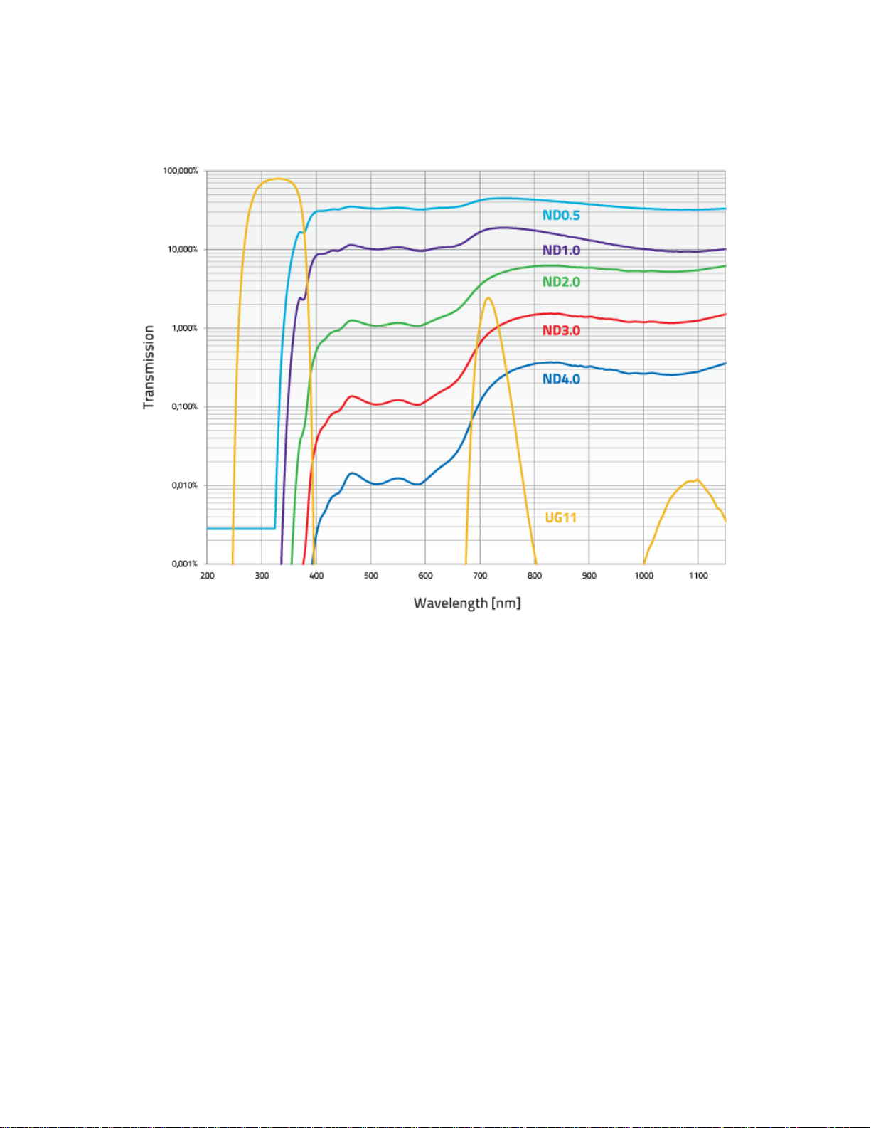
1.2.2.Sensor and Filter Spectral Responses
Figure 1-2 Attenuation Filter Transmission

11Beamage-3 User’s Manual Revision 4.0 12
Standa Ltd. All rights reserved
2. QUICK START PROCEDURE
These steps must be followed in the specified order.
1. Install the PC-Beamage-3.0 software.
2. Install the 11Beamage-3 USB driver by following the 11Beamage-3 Driver Installation Quick
Guide (refer to Annex B). The driver must be reinstalled if a new version of software was updated;
a. If necessary update the 11Beamage-3’s firmware, using the BeamageUpdater (refer to
Annex C);
3. Connect the 11Beamage-3 to a USB 3.0 port or USB 2.0 port;
a. If multiple 11Beamage-3 are used, please connect them all to the computer;
4. Start your laser and align in the 11Beamage-3 aperture;
5. Start the PC-Beamage-3.0 software. Select the desired 11Beamage-3 from the displayed list. The
green led button in the “Main Controls” indicates that communication has been established.
a. If multiple 11Beamage-3 are used, please start multiple instances of PC-Beamage-3.0
before pressing “Start Capture”;
6. Press “Start Capture”;
7. Let the auto-exposure find the correct exposure time. This should take a few seconds. If the
exposure time is at 100 ms and your beam is under exposed, please decrease the ND filter
attenuation. If the exposure time is at 0.2 ms and the beam is saturated (maximum is white)
please increase the ND filter attenuation;
8. Click on the “Subtract Background” in the Ribbon;
9. A message box will appear. Once this message appears, block your laser beam and click “OK”;
10. Once the “Please wait” message box disappears, you can unblock your laser beam;
11. The measures will appear in the “Home” tab on the right-hand side;
12. Choose the appropriate graphic for your measurement on the left hand-side:
a. 3D display;
b. 2D display;
c. XY display;
d. Beam tracking display.
11Beamage-3 User’s Manual Revision 4.0 13
Standa Ltd. All rights reserved
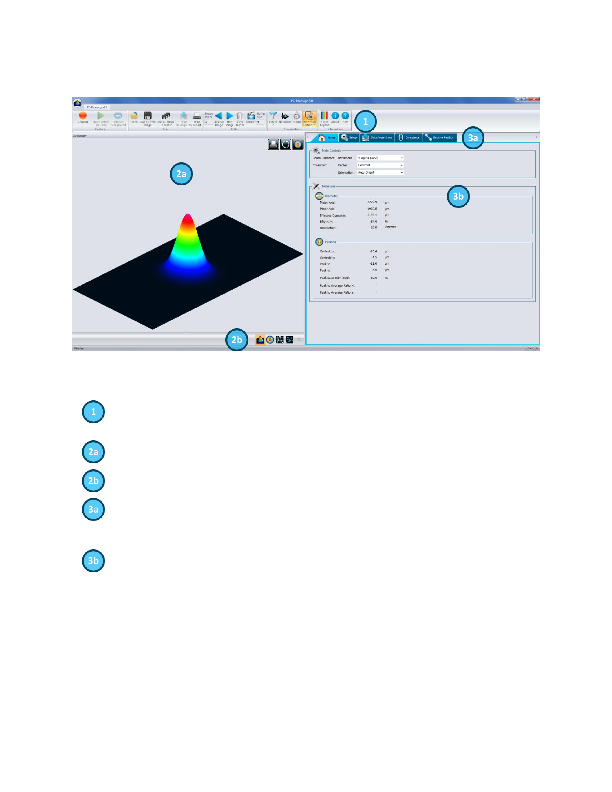
3. MAIN USER INTERFACE
Figure 3-1 PC-Beamage-3.0 User Interface
The Main Controls: The top portion of the software is in a ribbon format and includes all the
main controls. These are grouped by family, including Capture controls, File controls, Buffer
controls, and Data Computation which includes a very useful spatial filter and a normalizing
function.
Displays: The left-hand side of the software is the display panel. Three displays are available:
3D, 2D, and XY (cross-sectional graphs along the crosshairs).
Displays Selector: At any time, it is possible to change the type of display by selecting the
desired graphic (3D Display, 2D Display, XY Display).
Analysis Panel - Tab Selector: Choose between the Home, Setup or Data Acquisition panel
tab.
Analysis Panel - Controls: The right-hand side of the software contains the Home, Setup and
Data Acquisition tabs. The first tab (Home) allows the user to select the type of measurements
to be performed, it also shows the resulting measures of the beam. The second tab (Setup)
contains all the measurement parameters, such as the Exposure Time, Image Orientation,
Averaging, Active Area, and more. The third tab (Data Acquisition) lets the user specify the
desired acquisition parameters.

11Beamage-3 User’s Manual Revision 4.0 14
Standa Ltd. All rights reserved
4. THE MAIN CONTROLS
Figure 4-1 PC-Beamage-3.0 Main Controls
To give more room to the graphical display and less to the ribbon, you can minimize the ribbon by right
clicking on it and choosing “Minimize the ribbon”. You can retrieve the ribbon at any time by right clicking
on the upper portion of the window and unchecking “Minimize the ribbon”.
Figure 4-2 The PC-Beamage-3.0 Interface With and Without the Main Controls Ribbon
4.1. MULTIPLE 11BEAMAGE-3 MODE
It is possible to connect multiple 11Beamage-3 to a single computer. When you start the PC-Beamage-
3.0 the following window showing all the serial numbers of the connected cameras will appear. If
numerous 11Beamage-3 are connected to the computer, please select the desired camera. To connect to
another 11Beamage-3 simultaneously, start another PC-Beamage-3.0 instance and select another serial
number. You must start streaming after all the desired 11Beamage-3 have been connected to a PC-
Beamage-3.0 instance.
Figure 4-3 11Beamage-3 Selector for Numerous Connected 11Beamage-3

11Beamage-3 User’s Manual Revision 4.0 15
Standa Ltd. All rights reserved
Warning
Multiple 11Beamage-3 beam profilers can be connected to a single
computer. However, PC-Beamage-3.0 is not a multiple device software so
you need to open a new instance of the program for each camera that is
connected to your computer.
4.2. CAPTURE CONTROLS
The “Capture Menu” displays the 11Beamage-3 current status, controls the capture, and captures an
average detector background map.
Figure 4-4 Capture Controls
4.2.1.Camera Status
Figure 4-5 Camera Status
The software will automatically detect when a 11Beamage-3 is connected to the computer and it will be
indicated in the Camera Status with a green button, while a red button indicates that there is no
11Beamage-3 connected. When the PC-Beamage-3.0 is capturing an image, the status green button will
flash as well as the LED on the 11Beamage-3. Each time the 11Beamage-3’s pixels are capturing an
image, the LED will be off to avoid parasitic lighting from the LED. Note that clicking on this button will not
do anything since it is not a control button, but rather a status indicator.
4.2.2.Capture Button
Figure 4-6 Capture Button
To start capturing images with the 11Beamage-3, click on the “Start Capture”. If no 11Beamage-3 is
connected to the computer or if the “Animate” mode (refer to section 4.4.4) is on, this button will not be
available. Once the 11Beamage-3 starts streaming, the frame rate will be displayed below the button in
frames per second (fps). This measure includes the acquisition and computation time.
11Beamage-3 User’s Manual Revision 4.0 16
Standa Ltd. All rights reserved
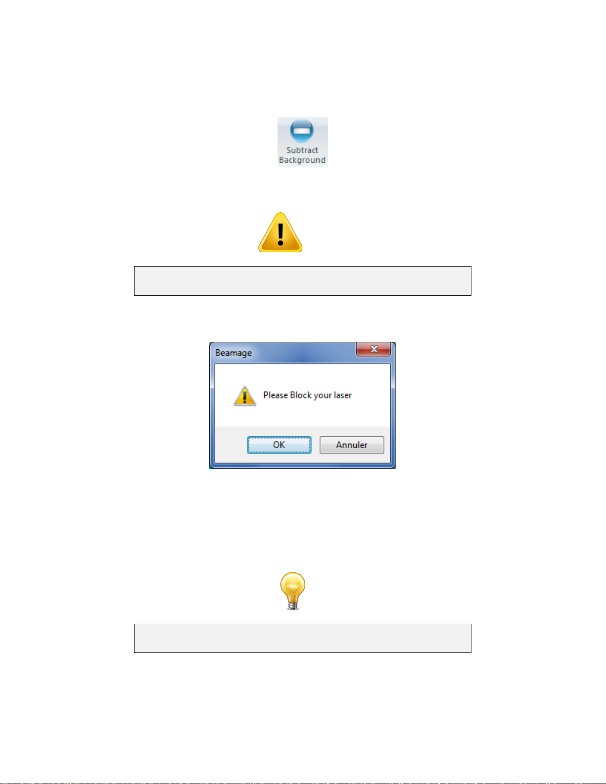
4.2.3.Subtract Background Button
Figure 4-7 Subtract Background Button
Warning
To abide by ISO-11146-3:2004 (Section 3) and have an accurate
measurement, a background subtraction must be done.
Once you have clicked the “Subtract Background” button, the following message box will appear:
Figure 4-8 Subtract Background Message Box
Once this message box appears, block the beam and then click on “OK”. The software will capture 10
images and average pixel by pixel to compute the average detector background map. A “Please Wait”
message box will appear while the software is capturing the average detector background map. The
detector background map will be subtracted from all the images that will follow. Note that once the
background subtraction has been done, the exposure time will no longer be in “Auto” mode and set to the
current exposure time.
Tip
Be sure to block your beam only when the Message Box appears and not
before.
11Beamage-3 User’s Manual Revision 4.0 17
Standa Ltd. All rights reserved
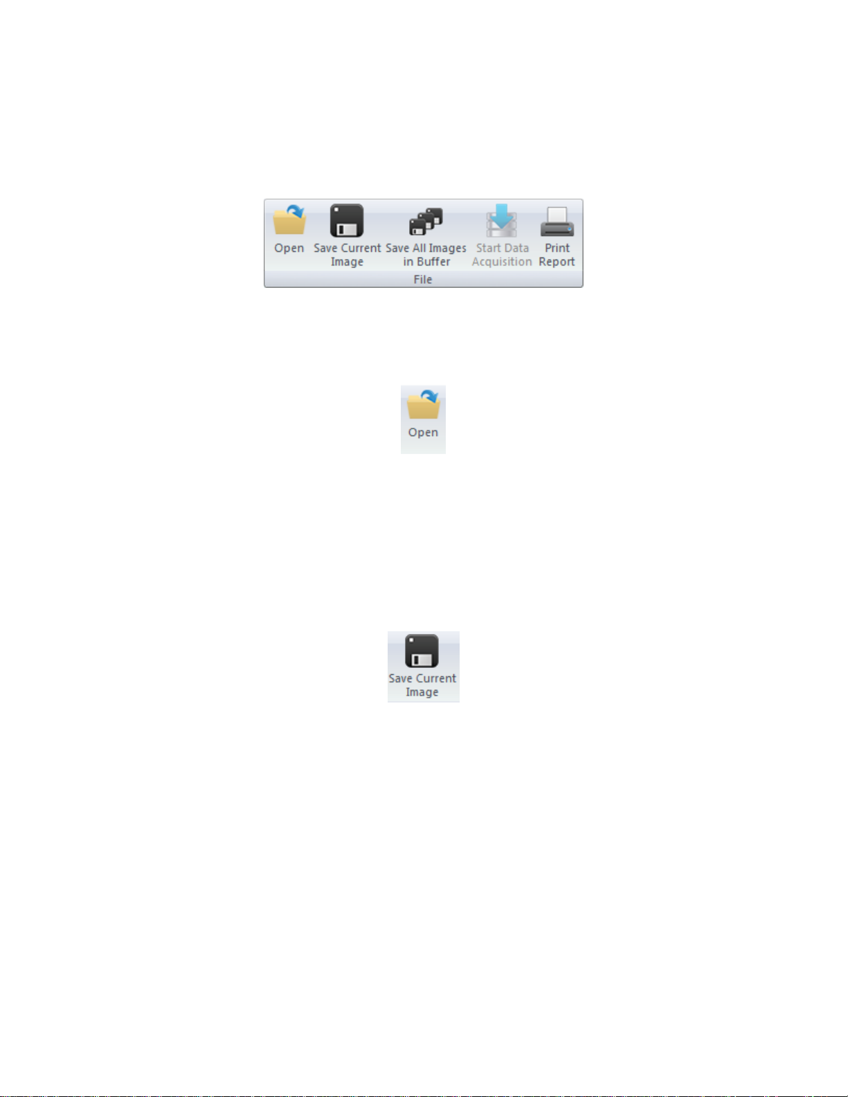
4.3. FILE CONTROLS
The “File Menu” opens and saves frames captured with the 11Beamage-3, and also prints a complete
report.
Figure 4-9 File Controls
4.3.1. Open
Figure 4-10 Open File Button
Click on the “Open” file button to retrieve previously saved data. The PC-Beamage-3.0 software will only
open native *.BMG files. The files can contain between 1 and 32 frames, depending on how the file was
created (refer to section 4.3.2 and 4.3.3). If the file was saved with multiple frames, it will be possible to
access all of them with the Buffer Control (refer to section 4.4).
4.3.2. Save Current Image
Figure 4-11 Save Current Image Button
Click on the “Save Current Image”button to save the currently displayed image. This option will only save
1 frame. Data can be saved in native *.BMG format, in text *.TXT format or in binary *.BIN format. Note
that only the *.BMG format can be re-opened with the PC-Beamage-3.0 software.
The *.TXT and the *.BIN files must be used with a compatible software. The *.TXT file saves a header
containing the measurements settings followed by the sensor’s output matrix. Every pixel output is
separated by a coma. The *.BIN file only saves the data and does not contain a header. The .*bin file
saves data on signed 32 bit integers.

11Beamage-3 User’s Manual Revision 4.0 18
Standa Ltd. All rights reserved
4.3.3.Save All Images in Buffer
Figure 4-12 Save All Images in Buffer Button
Click on the “Save All Images in Buffer”button to save all the frames stored in the buffer. Data can be
saved in native *.BMG format, in text *.TXT format or in binary *.BIN format. Note that only the *.BMG
format can be re-opened with the PC-Beamage-3.0 software. When opening the *.BMG file, all the stored
images will be accessible via the Buffer Controls menu including all the calculated measurement values
(refer to section 4.4).
When saving in *.TXT or *.BIN file, a series of files will be saved and identified with their respective buffer
index number. The *.TXT and the *.BIN files must be used with a compatible software. The *.TXT file
saves a header containing the measurements settings followed by the sensor’s output matrix. Every pixel
output is separated by a coma. The *.BIN file only saves the data and does not contain a header. The
.*bin file saves data on signed 32 bit integers.
4.3.4.Start Data Acquisition
Figure 4-13 Start Data Acquisition Button
Click on the “Start Data Acquisition” button to start the data logging of all the measurements displayed in
the “Home” tab. This function is only available while the camera is streaming. The acquisition parameters
can be modified in the “Data Acquisition” tab on the right-hand side of the user interface (refer to section
5.3).
It is only possible to save the beam profiling results shown in the measure tab (refer to section 5.1.2) in a
*TXT file. The *TXT file includes a header, containing the acquisition settings, followed by the data. Each
line corresponds to a single frame and all the measurements are separated by a tab. This file can be
opened in a spreadsheet software, such as Microsoft Excel.
It is also possible to save the images associated with the measurements saved in the *.TXT logging file.
Each image will be individually saved in a native *.BMG file. Each file will have the same filename as the
*.TXT file, followed by the corresponding increment.
Warning
Each *.BMG file can take up to 8.50 MB on the hard drive. Acquiring
multiple frames can quickly sum up to multiple GigaBytes.
Fast acquisition should only be done on the computer’s hard drive and
cannot be done on an external drive or on a server hard drive.

11Beamage-3 User’s Manual Revision 4.0 19
Standa Ltd. All rights reserved
4.3.5.Print Report
Figure 4-14 Print Report Button
Click on the “Print Report”button to print a complete report of the current measurement. A print preview
will appear in the PC-Beamage-3.0 software. To print the report, click on “Print”. To exit without printing,
click “Exit”. The buttons are located on the right-hand side.
Figure 4-15 Print Report Preview
The report fits on 2 pages. The first page presents the 3D and 2D images, measurement results, and the
11Beamage-3’s settings.
Table of contents


