Standard Horizon FF525 User manual

FF525 BLACK BOX FISH FINDER
INSTALLATION MANUAL

Page 4 FF525 Installation Manual
FCC Compliance Statement
ThisdevicecomplieswithPart15oftheFCClimitsforClassAdigitaldevices.This
equipment generates, uses and can radiate radio frequency energy and, if not
installedorusedinaccordancewiththeinstructionsmaycauseharmfulinterference
with radio communications.
Thereisnoguaranteethatinterferencewillnotoccurinaparticularinstance.Ifthis
equipment does cause harmful interference to other equipment, try to correct the
problem by relocating the equipment.
Consult an authorized STANDARD HORIZON dealer or other qualified service
technician if the problem cannot be corrected. Operation is subject to the following
conditions: (1) This device cannot cause harmful interference, and (2) this device
must accept any interference received, including interference that may cause
undesired operation.
CAUTION
·The FF525 contains dangerous high-voltage circuits which only experienced
technicians can handle.
·STANDARD HORIZON will not be liable for errors contained herein, or for
incidental or consequential damages in connection with the performance or use
of this material.
·Becausewefrequently update our software and applications, the pictures shown
through this Owner’s Manual may be slightly different from what you see.
WARNING
·When plugging in or unplugging a transducer to the FF525 make sure power is
turned off.
Copyright 2013. YAESU MUSEN CO., LTD. All rights reserved. Printed in Italy.
No portion of this manual may be reproduced without the permission of YAESU MUSEN CO., LTD.
CODE: Installation Manual - Issue E - 100413e

FF525 Installation Manual Page 5
TABLE OF CONTENTS
1. INTRODUCTION ...................................................................................................................6
1.0 GENERAL INFORMATION...............................................................................6
1.1 PACKING LIST .................................................................................................7
1.1.0 Replacement Parts .............................................................................. 7
2. MOUNTING THE FF525 .......................................................................................................8
2.0 INSTALLATION.................................................................................................8
2.1 CONNECTIONS................................................................................................8
2.2 POWER CONNECTIONS................................................................................. 9
2.3 GPS CHART PLOTTER CONNECTIONS .......................................................9
2.3.1 Tee Cable .............................................................................................9
2.4 OPTIONAL CONNECTIONS ..........................................................................11
2.4.0 NMEA Output ..................................................................................... 11
2.4.1 Alarm Buzzer......................................................................................11
2.4.2 Temperature Sensor .......................................................................... 11
3. TRANSDUCER ...........................................................................................................12
3.0 TRANSDUCER MOUNTING .......................................................................... 12
3.0.0 Power Boats .......................................................................................12
3.0.1 Sailboats.............................................................................................12
3.0.2 Transducer Types ..............................................................................13
3.0.3 Low Profile Thru-Hull.......................................................................... 13
3.0.4 Transom (power boats only) ..............................................................13
3.0.5 Fairing Block ...................................................................................... 13
3.0.6 In-hull..................................................................................................13
3.0.7 Optional Transducer ID Sensors ......................................................13
3.0.8 Fish Finder Basics .............................................................................14
4. FF525 SPECIFICATIONS ..........................................................................................15
5. INSTALLATIONS TIPS .............................................................................................. 16
INDEX ......................................................................................................................................17

Page 6 FF525 Installation Manual
1. INTRODUCTION
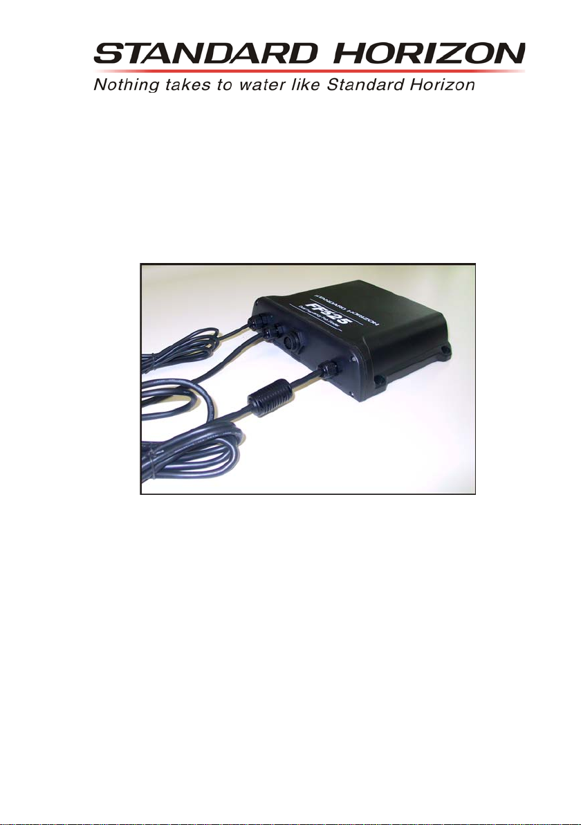
This manual provides installation of the FF525 and associated 600W or 1kW transducers.
Foroperations, refer to the FF525 Operation Manual for CP180/CP180i, CP190i, CP300/CP300i,
CPV350,CP390i,CP500,CPV550,CP590andtheFF525OperationManualforCPN700i,CPN1010i.
1.0 GENERAL INFORMATION
The FF525 advanced features include:
·16/256 colors display user selectable
·A-Scope (displays Sonar Echo in real time)
·Preset modes (Fish, Cruise)
·2xand4xZoom(capabilitytomagnifyany partof theFish Finderimage ofafixedrate)
·Bottom Lock (capability to magnify a user defined range around the bottom)
·White Line (help distinguish between fish and bottom, when fish are swimming close
to the bottom)
·Sensitivity Time Control (STC) reduces Surface Clutter shown on the display by
reducing echoes from water disturbances
·Surface Noise Filter (suppresses the displaying of Surface Clutter)
·Interference Rejection (allows reducing interference from other boats/Fish Finders)
·Noise Filter
·Fish Symbol feature
·Transducer ID (automatically selects power output and parameters for best performance).
·Dual Frequency: 50 and 200kHz with the capability to display the two frequencies at
the same time.
·Dual Power output: 600/1000W (4800/8000Wpp) depending on the transducer
connected. Refer to Par. 3.0.7 "Optional Transducers ID Sensors".
·Max Depth*: 1KW - 1200ft (365m) at 200kHz, 4000ft (1219m) at 50kHz
600W - 700ft (213m) at 200kHz, 1500ft (457m) at 50kHz
·Min Depth: 2.5ft (0.8m) at 200kHz, 5ft (1.6m) at 50kHz
·Max Typical*:1KW - 980ft (299m) at 200kHz, 2700ft (823m) at 50kHz
600W - 600ft (183m) at 200kHz, 1350ft (411m) at 50kHz
NOTE*
Thisisnotaguaranteedspecification.Theactualmaximumdepthcapabilityofthesystemdepends
on the type of transducer fitted, the reflectivity of the bottom, water condition, etc.
·Speed through water (if available on transducer)
·Dual temperature inputs Sensor (One channel TEMP1, Optional second channel
TEMP2) - if available on transducer
·Trip Log
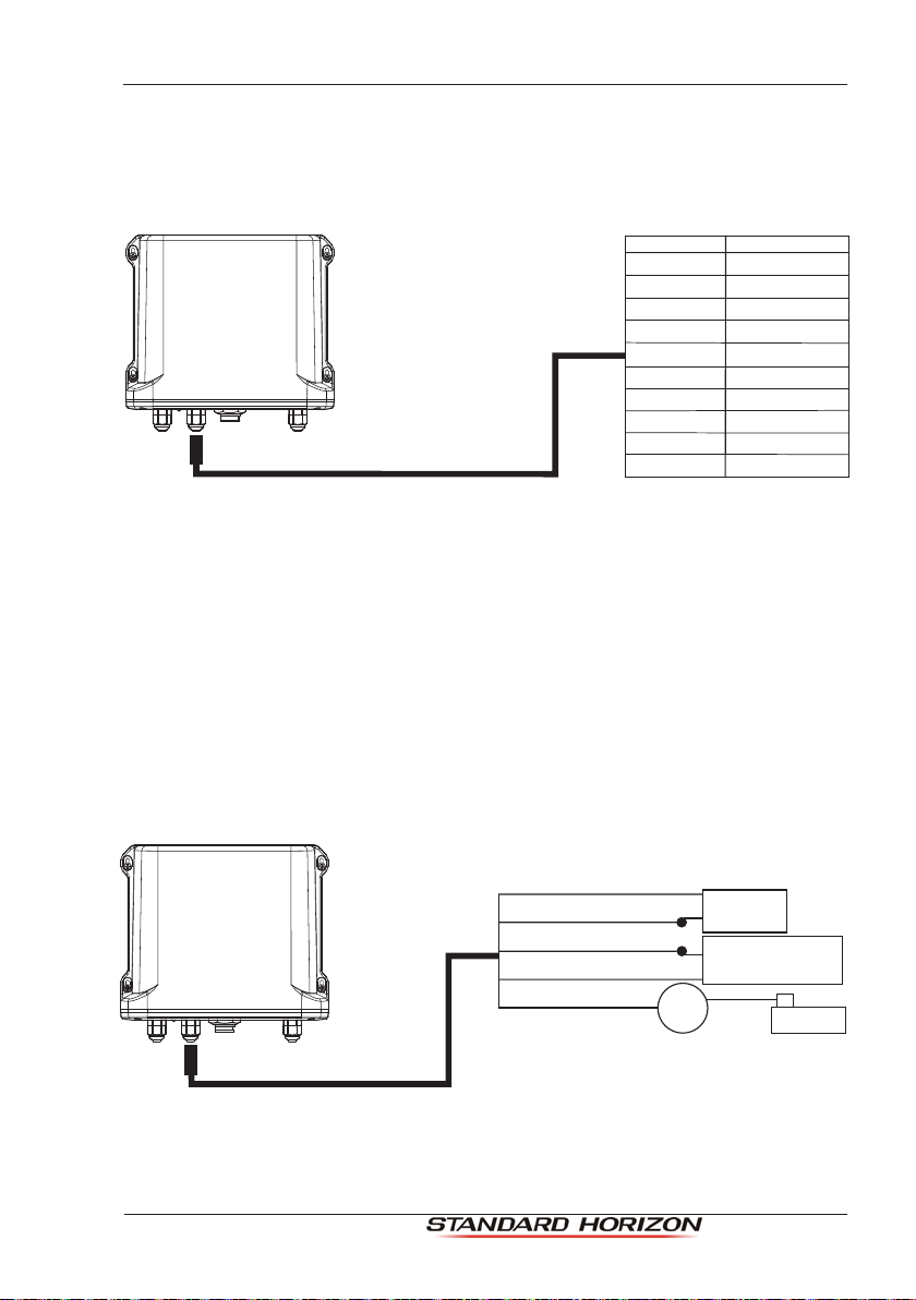
·External buzzer connections (buzzer not supplied)
·Alarms: Shallow, Depth, Temperature Upper and Lower
NOTE
The following STANDARD HORIZON transducers will only operate with the FF525: DST520,
DST521, DST523, DST525, DST526, DST527 and DST528A.

FF525 Installation Manual Page 7
PerformanceoftheFF525usedinconjunction withoptionaltransducers(soldseparately)
willvarybasedonwaterconditions,bottomcomposition,boathull,vesselspeed,installation,
and specific transducer model. This includes but is not limited to both minimum and
maximum depth performance.
1.1 PACKING LIST
When the package containing the FF525 is first opened, please check for the following
contents.
1.1.0 Replacement Parts
Replacement part Item
S8101640 Tee Cable FF525
S8101641 Power Cable FF525
EM040X104 FF525 Operation Manual (for CP180/CP180i, CP190i, CP300/CP300i, CPV350, CP390i,
CP500, CPV550 and CP590)
EM040X152 FF525 Operation Manual (for CPN700i and CPN1010i)
EM040X502 FF525 Installation Manual
XUAIR0029 DST521 Paddlewheel repair kit
XUAIR0030 DST521 Mounting bracket
XUAIR0018 DST526 Paddlewheel repair kit

Page 8 FF525 Installation Manual
2. MOUNTING THE FF525
The FF525 must be properly installed according the following instructions to get the best
possible performance. NOTE
TRANSDUCER: refer to Chapter 3and to the Installation Manual supplied with the Transducer.
2.0 INSTALLATION
The FF525 is designed to be mounted horizontally or vertically to enable it to be installed
in the most convenient position. After the cables have been run, mount the FF525 in the
desired location using the supplied hardware.
-
4.56” [ ]116 mm
7.20” [ ]183 mm
Figure 2.0 - The FF525 Installing
2.1 CONNECTIONS
Figure 2.1 - The FF525

FF525 Installation Manual Page 9
2.2 POWER CONNECTIONS
TheinstallationofaswitchisnecessarytoturnOnorOfftheFF525.STANDARDHORIZON
recommends connecting the FF525 and Chart Plotter to the same power switch (not
supplied)andfused sourceasshowninthe followingimagesbelow.Normallyspare rocker
switch on a dash is used.
2.3 GPS CHART PLOTTER CONNECTIONS
TheFF525 isconnectedtoSTANDARDHORIZON ChartPlottersvia theTeeCable. Refer
to the following images below.
2.3.1 Tee Cable
IftheTeeCableconnectoristoolargetoroutethroughyourboat,theFF525canbeopened
to remove the cable for easier routing. Also if the Tee Cable is not long enough cable can
alsobeadded.Forsomeinstallations,theTeeconnectormayprotrudetoofarfromtherear
of the Chart Plotter when the power cable is connected also. If this is the case the Tee
connector may be removed. After removal connect each wire of the FF525 and the Chart
Plotter via a terminal strip in a dry location or solder and heat shrink wire color to wire color
as shown in the table below:
FF525
Gray
White
Green
Gray
White
Green
Chart Plotter
Figure 2.3.1 - FF525 - Chart Plotter table
Figure 2.3.1a - Removing Power and Tee cables
WARNING
Before following the steps below, disconnect 12VDC from the FF525.
1. Open the FF525 box by unscrewing the four screws.
2. Once the screws are removed, pull out the panel and the Printed Circuit Board (PCB).
3. Losen and remove the Green, White and Gray wires from the terminal strip.
4. Then lossen the cap and pull the wires from the inside of the FF525.
5. Routethe Tee Cableasneed through thevesseland or addadditionalcable if needed.
6. Ifthecapwasremoved,insertitontotheTeeCable,theninsertthecableintotheFF525.

Page 10 FF525 Installation Manual
7. Reinstallthewiresintotheterminalstrip.FromlefttorightwiththewiresareGray,White
and Green.
8. Tighten the cap to hold the Tee Cable in place.
9. Push the panel towards the case (be sure to have the rubber gasket positioned
correctly).
10. Close the FF525 box by reinstalling the four screws.
Cable
color
Function
Terminal
strip
D
E
Black
Red
GND
POWER SUPPLY 10-35 VDC
FGHM
IL
1
2
3
4
5
6
7
8
1
2
3
4
5
6
7
8
GPS
chart plotter
Female 8 Pin
Power &
I/O cable
of
GPS
chart plotter
Male 8 Pin
POWER Cable
CHART PLOTTER Cable
X
X
Terminal
strip Cable
color GPS chart plotter
Function
Function
A
B
C
FF TX+
FF RX+
FF GND
Gray
White
Green
Port2 Input
Port2 Output
NMEA Common GND
ABC
DE
Figure 2.3.1b - Internal connections
IMPORTANT
Refer to software setup section after connections have been made.

FF525 Installation Manual Page 11
2.4 OPTIONAL CONNECTIONS
The FF525 is supplied with connections that allow the FF525 to be connected to the
following external devices:
a. NMEA device capable of listening to DBT, DPT, VHW, VLW, MTW
b. Temperature sensor (10K ohms at 77°F)
c. 12VDC Alarm Buzzer (400mA max current draw)
WIRE COLOR
BLACK
FUNCTION
RED
WHITE
GREEN
GRAY
YELLOW
BROWN
BLUE
GND
Not connected
NMEA Output(+)
NMEA GROUND
Temp 2 INPUT(+)
Alarm OUTPUT(+)
Not connected
Not connected
ORANGE Not connected
Not connected
PINK
Figure 2.4 - The FF525 Optional Connections
2.4.0 NMEA Output
Thefollowingsentencesareoutput:DPTandDBT(Depth),VHW(Speed),VLW(TripLog),
MTW (Water Temperature), XDR (External Temperature Sensor).
2.4.1 Alarm Buzzer
Thisconnection has thecapabilitytodrive abuzzerthatdraws 400mA. Any12VDCbuzzer
within the current draw requirements can be connected.
2.4.2 Temperature Sensor
Any thermistor type temp sensor that produces 10K ohms at 77°F can be connected.
White,NMEA output
Green,common
Black,ground
Yellow, Ext.Temp sensor
Blue,Alarm output 12VDC
Buzzer 12V Battery
+
NMEA
Device
External
Temp Sensor
Figure 2.4.2 - Optional Connections

Page 12 FF525 Installation Manual
3. TRANSDUCER
WARNING
WHEN PLUGGING IN OR UNPLUGGING A TRANSDUCER TO THE FF525 MAKE SURE
POWER IS TURNED OFF.
The transducer is a device that transmits and receives sound waves into the water. The
activecomponent insidethetransducer iscommonlyreferred toasan elementbutactually
is a piezoelectric ceramic material.
3.0 TRANSDUCER MOUNTING
3.0.0 Power Boats
Basicallytherearetwohulltypesofpowerboats:PlaningandDisplacement.Inthefollowing
pictures the boxes with lines are where the transducer should be installed.
Figure 3.0.0 - Planing (on the left) and Displacement (on the right)
The planing hull allows the boat to rise quickly out of the water, allowing the boat to travel
at higher speeds.
Thedisplacementhulldoesnotrideupontopofthewater;ratheritpushesthroughthewater.
3.0.1 Sailboats
Mount the transducer in the first front 1/3 part of the boat, just forward of or the side of the
keel.
Figure 3.0.1 - Fin Keel (on the left) and Full Keel (on the right)
Figure 3.0.1a - Mounting Area

FF525 Installation Manual Page 13
3.0.2 Transducer Types
Since there are many different shapes and sizes of hulls, STANDARD HORIZON offers a
range of Depth transducers to fit the vessels requirements.
3.0.3 Low Profile Thru-Hull
Iftheuserisplanningtomountathru-hulltransducerfirsthehastoknowthe dead rise angle
wherethetransducerwillbelocatedontheboat.The"DeadRise"isanauticaltermthatrefers
to the angle of the hull where the transducer will be mounted (see picture below). Specific
transducers are designed to be installed on boats with different dead rises.
Figure 3.0.3 - Dead rise
3.0.4 Transom (POWER BOATS ONLY)
The back of a boat is called the transom this is where this transducer is mounted. This
transducer has a bracket that is screwed down onto the hull.
3.0.5 Fairing Block
Used when a hull is over 10-15 degrees.
·The Fairing Block is used to compensate the dead rise of the hull. The Fairing Block
STANDARD HORIZON offers is made from hard plastic which fits around the
transducer.
·To install the transducer and Fairing Block, the user measures the dead rise of the
hull and cuts the Fairing Block to that angle. One half of the Fairing Block mounts on
the inside while the other part of the Fairing Block mounts on the outside of the hull.
3.0.6 In-hull
This transducer is epoxyed to the inside of the hull that is not more than 1/2 inch thick and
is solid not cored.
3.0.7 Optional Transducer ID Sensors
Figure 3.0.7 - Optional Transducers

Page 14 FF525 Installation Manual
3.0.8 Fish Finder Basics
The FF525 consists of a high power transmitter, sensitive receiver and a transducer. The
FF525sendsanelectricalpulsetothetransducer,whichcontainsanelementthatconverts
thepulseintoacoustic(sound)waves,whichissentthroughthewater.Asthiswavetravels
from the transducer to the bottom, it may strike fish, structures, thermoclines (temperature
changes in the water). When the wave strikes an object(s) a certain amount of the wave is
reflected back to the transducer depending on the composition and shape of the object.
When the reflected wave is returned to the transducer it is converted into a voltage and is
amplified by the receiver, processed and sent to the display. The speed of sound in water
is roughly 4800ft/sec, so the time lapse between the transmitted signal and the received
echo can be measured and the distance to the object determined.
Figure 3.0.8 - Fish Finder working principle

FF525 Installation Manual Page 15
4. FF525 SPECIFICATIONS
Power supply : 10 - 35 Volt dc
Max stand by current draw : 1KW:142mA at 12 Volt dc
: 600W:100mA at 12 Volt dc
Max current draw : 1KW:1.42A at 12 Volt dc
: 600W:1A at 12 Volt dc
Power Output : 600/1000W (4800/8000W Peak to Peak)
Display Colors : 16/256 colors user selectable
Display Vertical Resolution : 400 pixels ONCPV350/CP300/CP300i/CP390i/CPV550/CP500
/CP590/CPN700i/CPN1010i
: 200 pixels ON CP180/CP180i/CP190i
Frequency : Dual 50 and 200kHz
Max Depth* : 1KW:1200ft(365m) at 200kHz; 4000ft(1219m)at50kHz
: 600W:700ft (213m) at 200kHz; 1500ft (457m) at 50kHz
Min Depth : 2.5ft (0.8m) at 200kHz; 5ft (1.6m) at 50kHz
Max Typical* : 1KW:980ft (299m) at 200kHz; 2700ft (823m) at 50kHz
: 600W:600ft (183m) at 200kHz; 1350ft (411m) at 50kHz
NOTE*
Thisisnotaguaranteedspecification.Theactualmaximumdepthcapabilityofthesystemdepends
on the type of transducer fitted, the reflectivity of the bottom, water condition, etc.
NMEA Output sentences : Depth: DBT, DPT
Temperature: MTW
Speed (with DST526): VHW
Weight : 2.20 LBS (1 kg)
Operating temperature range: 32°F to 122°F (0°C to +50°C)
Storage temperature range : -4°F to 158°F (-20°C to +70°C)
Dimensions - inch (mm) :
7.73” [196.4mm]
1.96” [50mm]
6.5” [164.96mm]
1.96” [50mm]
Figure 4 - FF525 Dimensions [inch/mm]

Page 16 FF525 Installation Manual
5. INSTALLATIONS TIPS
5.0 How can I disconnect the cables from the FF525 in case I need to do so
for the installation?
·Open the FF525 box by unscrewing the four screws (see Figure on Par. 2.3.1).
·Oncethe screws are removed, pull out the panel andthe Printed Circuit Board (PCB).
Unscrew the cables from the PCB.
·Wire the cables as needed.
·Reconnect the cables to the PCB.
·Push the panel towardsthe case (be sure to have well positioned the rubber gasket).
Close the FF525 box by screwing the four screws.
5.1 LED Status Indicator
The FF525 has a small LED that blinks. There are seven different LED behaviours,
representing seven different diagnostic conditions described below.
·OFF :DC power is not being supplied to the
FF525.
· ON CONTINUOUSLY :The transducer is not connected to the
ChartPlotterand problemwithcableofthe
transducer cable.
· 1 LONG FLASH EVERY 2 SECONDS :The FF525isnot connected withtheChart
Plotter. Black Box is working properly, but
it is not connected to the Chart Plotter.
Configure the I/O Port.
· 2 SHORT FLASHES EVERY 2 SECONDS:The FF525 is connected to the Chart
Plotter and is operating correctly.
· 3 SHORT FLASHES EVERY 2 SECONDS: A not-STANDARD HORIZON transducer
(without transducerID)hasbeenconnected
· 4 SHORT FLASHES EVERY 2 SECONDS: No transducer connected.

FF525 Installation Manual Page 17
INDEX
16/256colors.............................................. 6, 15
A
A-Scope ............................................................ 6
Alarm Buzzer ................................................... 11
Alarms ............................................................... 6
B
Black Box ........................................................ 16
Bottom Lock ...................................................... 6
buzzer ........................................................ 6, 11
C
Compliance Statement ...................................... 4
CONNECTIONS................................................ 8
CP180 ........................................................ 6, 15
CP180i ....................................................... 6, 15
CP190i ....................................................... 6, 15
CP300 ........................................................ 6, 15
CP300i ....................................................... 6, 15
CP390i ....................................................... 6, 15
CP500 ........................................................ 6, 15
CP590 ........................................................ 6, 15
CPN1010i................................................... 6, 15
CPN700i..................................................... 6, 15
CPV350...................................................... 6, 15
CPV550...................................................... 6, 15
Cruise................................................................ 6
D
DBT .......................................................... 11, 15
DC power ........................................................ 16
dead rise ......................................................... 13
Depth .................................................. 6, 11, 15
Dimensions ..................................................... 15
Displacement .................................................. 12
Display Colors ................................................. 15
DPT .......................................................... 11, 15
DST520 ............................................................. 6
DST521 ............................................................. 6
DST523 ............................................................. 6
DST525 ............................................................. 6
DST526 ...................................................... 6, 15
DST527 ............................................................. 6
DST528A .......................................................... 6
DualFrequency ................................................. 6
Dual Power output ............................................. 6
E
Externalbuzzer ................................................. 6
externaldevices .............................................. 11
External TemperatureSensor ......................... 11
F
Fairing Block ................................................... 13
FCC................................................................... 4
features ............................................................. 6
Fin Keel ........................................................... 12
Fish ................................................................... 6
fish .................................................................. 14
Fish Finder ...................................................... 14
Fish Symbol ...................................................... 6
Frequency ....................................................... 15
Full Keel .......................................................... 12
I
In-hull .............................................................. 13
INSTALLATION................................................. 8
installation ....................................................... 16
InterferenceRejection ....................................... 6
Internalconnections ........................................ 10
K
keel ................................................................. 12
L
LED Status ...................................................... 16
Low Profile Thru-Hull ....................................... 13
M
Max current draw ............................................. 15
MaxDepth .................................................. 6, 15
MaxTypical ................................................ 6, 15
Min Depth ................................................... 6, 15
MOUNTING..................................................... 12
MountingArea ................................................. 12
Mounting bracket ............................................... 7
MOUNTING THE FF525 ................................... 8
MTW ........................................................ 11, 15
N
NMEA device .................................................. 11
NMEA Output ........................................... 11, 15
Noise Filter ........................................................ 6
O
Operatingtemperature .................................... 15
OperationManual .............................................. 6
OPTIONAL CONNECTIONS........................... 11
Optional Transducer ........................................ 13
P
package ............................................................ 7
PACKING LIST ................................................. 7
Paddlewheel repair kit ....................................... 7
PCB............................................................ 9, 16
Planing ............................................................ 12
Power Boats .................................................... 12
Power Cable...................................................... 7
POWER CONNECTIONS ................................. 9

Page 18 FF525 Installation Manual
Power Output .................................................. 15
Power supply ................................................... 15
powerswitch...................................................... 9
Preset modes .................................................... 6
Printed Circuit Board .................................. 9, 16
R
receiver ........................................................... 14
Replacement Parts ............................................ 7
Resolution ....................................................... 15
S
Sailboats ......................................................... 12
Sensitivity Time Control..................................... 6
Sonar Echo ....................................................... 6
sound wave ..................................................... 12
SPECIFICATIONS .......................................... 15
Speed....................................................... 11, 15
speed .............................................................. 14
Speed through water ......................................... 6
STC ................................................................... 6
Storagetemperature ....................................... 15
Surface Clutter .................................................. 6
Surface Noise Filter ........................................... 6
switch ................................................................ 9
T
Tee Cable.............................................. 7, 9, 10
Tee connector ................................................... 9
Temperature.................................................... 15
temperature inputs Sensor ................................ 6
Temperature Sensor ....................................... 11
thermocline...................................................... 14
thru-hulltransducer ......................................... 13
TRANSDUCER ............................................... 12
transducer ................................................ 14, 16
Transducer ID ................................................... 6
TRANSDUCER MOUNTING ........................... 12
Transducer Types ........................................... 13
transmitter ....................................................... 14
Transom .......................................................... 13
Trip Log ...................................................... 6, 11
V
VHW ........................................................ 11, 15
VLW ................................................................ 11
voltage............................................................. 14
W
Water Temperature ......................................... 11
wave ................................................................ 14
Weight............................................................. 15
White Line ......................................................... 6
working principle ............................................. 14
X
XDR................................................................. 11
Z
Zoom ................................................................. 6

FF525 Installation Manual Page 19
S T A N D A R D H O R I Z O N L I M I T E D W A R R A N T Y
STANDARD HORIZON (the Marine Division of YAESU USA) warrants, to the original purchaser
only,eachnewMarineProduct("Product")manufacturedand/orsuppliedbySTANDARDHORIZON
against defects in materials and workmanship under normal use and service for a period of 3 years
from the date of purchase.
Intheeventofadefect,malfunctionorfailureoftheProductduringthewarrantyperiod,STANDARD
HORIZON's liability for any breach of contract or any breach of express or implied warranties in
connection with the sale of Products shall be limited solely to repair or replacement, at its option,
of the Product or part(s) therein which, upon examination by STANDARD HORIZON, appear to be
defective or not up to factory specifications. STANDARD HORIZON may, at its option, repair or
replace parts or subassemblies with new or reconditioned parts and subassemblies.
STANDARD HORIZON will not warrant installation, maintenance or service of the Products. In all
instances,STANDARDHORIZON's liability fordamagesshall not exceed thepurchaseprice of the
defective Product.
STANDARD HORIZON will pay all labor and replacement parts charges incurred in providing the
warranty repair service except where purchaser abuse or other qualifying exceptions exist. The
purchaser must pay any transportation expenses incurred in returning the Product to STANDARD
HORIZON for service.
This limited warranty does not extend to any Product which has been subjected to misuse, neglect,
accident, incorrect wiring by anyone other than STANDARD HORIZON, improper installation, or
subjected to use in violation of instructions furnished by STANDARD HORIZON, nor does this
warranty extend to Products on which the serial number has been removed, defaced, or changed.
STANDARD HORIZON cannot be responsible in any way for ancillary equipment not furnished by
STANDARD HORIZON which is attached to or used in connection with Products, or for the
operationof theProductwithanyancillary equipment,andallsuchequipment is expresslyexcluded
from this warranty. STANDARD HORIZON disclaims liability for range, coverage, or operation of
the Product and ancillary equipment as a whole under this warranty.
STANDARD HORIZON reserves the right to make changes or improvements in Products, during
subsequent production, without incurring the obligation to install such changes or improvements
on previously manufactured Products. The implied warranties which the law imposes on the sale
of this Product are expressly LIMITED, in duration, to the time period specified above. STANDARD
HORIZON shall not be liable under any circumstances for consequential damages resulting from
theuse and operation of thisProduct, or from the breachof this LIMITEDWARRANTY, any implied
warranties, or any contract with STANDARD HORIZON. IN CONNECTION WITH THE SALE OF
ITS PRODUCTS, STANDARD HORIZON MAKES NO WARRANTIES, EXPRESS OR IMPLIED
ASTOTHEMERCHANTABILITYORFITNESSFORAPARTICULARPURPOSEOROTHERWISE,
EXCEPT AS EXPRESSLY SET FORTH HEREIN.
SomeCountriesinEuropeandStatesoftheUSAdonotallowtheexclusionorlimitationofincidental
or consequential damages, or limitation on how an implied warranty lasts, so the above limitation
or exclusions may not apply. This warranty provides specific rights, there may be other rights
available which may vary between countries in Europe or from state to state within the USA.
PLEASE NOTE
United States: To receive warranty service, the purchaser must deliver the Product, transportation and
Insurance prepaid, to STANDARD HORIZON (Marine Division of YAESU USA) - Attention Factory Service -
6125Phyllis Drive-Cypress, CA90630,include proofofpurchase indicatingmodel,serial number anddate of
purchase.ThiswarrantyonlyextendstoProductssold withinthe50StatesoftheUnited StatedofAmericaand
the District of Columbia.
Europe: Contact details for warranty in Europe are available from the dealer in your country or from
www.standardhorizon.co.uk where details of warranty terms and contact details for Europe can be obtained.
For Limited Warranty details outside United States and Europe, contact the dealer in your country.

Page 20 FF525 Installation Manual
Yaesu UK Ltd
Unit 12, Sun Valley Business Park
Winnall Close
Winchester SO23 OLB
United Kingdom
Tel: +44 (0)1962 866667
Fax: +44 (0)1962 856801
Email: sales@yaesu.co.uk
Declaration of Conformity
Nr. YUK-DOC-1214-11
We, Yaesu UK Ltd. certify and declare under our sole responsibility that the following equipment
complies with the essential requirements of the Directive 1999/5/EC, with the provisions of
Annex III (Conformity Assessment procedure referred to in article 10)
T
yp
e of E
q
ui
p
ment: Fishfinder
Brand Name: Standard Horizon
Model Number FF525
Manufacturer TWS S.r.l
Address of Manufacturer: Via Zacca
g
na 6, 54033 Carrara Ital
y
Applicable Standards:
This equipment is tested to and conforms to the essential requirements of directive, as included
in following standards:
Test Standard
Conducted Emissions
Radiated Emissions
Radiated interference
IEC EN 60945:2003/11
Electrostatic Dischar
g
e ESD
Conducted RF interference
Conducted RF immunity
IEC EN 60945:2003/11
Com
p
ass Safe Distance IEC EN 60945:2003/11
ISO/R 694
EFT
–
Bursts Fast Transients IEC EN 60945:2003/11
DC Power Interru
p
tions,
Variation and Polarity
inversions
IEC EN 60945:2003/11
Safet
y
: Part 1
General Requirements
IEC EN 60950-1:2006/A1:2010
The technical documentation as required by the Conformity Assessment procedures is kept at
the following address:
Company: Yaesu UK Ltd
Address: Unit 12, Sun Valley Business Park,
Winnall Close, Winchester SO23 0LB
Technical Construction File: Issued by Yaesu Musen Co., Ltd., Tokyo, Japan
File No: UK001214
Drawn up in: Winchester, United Kingdom
Date: 26
th
January 2012
Name and position: PCJ Bigwood,
Technical Sales Manager
Other manuals for FF525
4
Table of contents
Other Standard Horizon Fish Finder manuals

Standard Horizon
Standard Horizon FF520 User manual

Standard Horizon
Standard Horizon CPF180I User manual

Standard Horizon
Standard Horizon FF520 Operating instructions

Standard Horizon
Standard Horizon CPF390i User manual

Standard Horizon
Standard Horizon FF525 User manual

Standard Horizon
Standard Horizon CP190i User manual

Standard Horizon
Standard Horizon FF520 User manual

Standard Horizon
Standard Horizon CPF180I User manual

Standard Horizon
Standard Horizon CPF180I User manual

Standard Horizon
Standard Horizon CP1000C Installation and operating instructions