Standex TRI-STAR Cyclone Series User manual
1
INSTALLATION AND OPERATING INSTRUCTIONS
Cyclone
SERIES
ELECTRIC CONVECTION OVENS
Models: TSCO-E1 and TSDCO-E1
INTENDED FOR OTHER THAN HOUSEHOLD USE
RETAIN THIS MANUAL FOR FUTURE REFERENCE
OVEN MUST BE KEPT CLEAR OF COMBUSTIBLES AT ALL TIMES
FOR YOUR SAFETY: Do not store or use gasoline or other flammable vapors or
liquids in the vicinity of this or any other appliance.
WARNING: Improper installation, adjustment, alteration, service or maintenance
can cause property damage, injury or death. Read the Installation, Operating and
Maintenance Instructions thoroughly before installing or servicing this equipment.
WARNING: Initial heating of oven may generate smoke or fumes and must be
done in a well-ventilated area. Overexposure to smoke or fumes may cause
nausea or dizziness.
This equipment has been engineered to provide you with year round dependable service when used
according to the instructions in this manual and standard commercial kitchen practices.
P/N 21709212 09/12
TRI-STAR MANUFACTURING
729 3
RD
Avenue
Dallas, TX 75226
Phone : +1 (714) 424-9380
Fax : +1 (714) 424-9385 www.tri-starmfg.com Web
Toll Free : +1 (866) 782-7462

2
CONTENTS
I. INSTALLATION INSTRUCTIONS
SECTION ITEM PAGE
A Receiving ..................................................... 2
B Set-up/Mounting .......................................... 2
C Installation with Casters ............................... 3
D Location Minimum Clearances ................. 3
E Electrical Connections ................................. 4
F Flue Connection Ventilation ......................... 5
G Initial Cleaning ............................................. 5
H System Check – Rotary Controls ................. 5
II. OPERATING INSTRUCTIONS
SECTION ITEM PAGE
A General Instructions...................................... 6
B Operation Sequence for Rotary Controls ...... 6
1. Cook Only ................................................. 6
2. Timed Cooking ......................................... 6
3. Cook Hold.............................................. 6
4. Steam Injection (Optional) ........................ 7
5. Oven Cool Down....................................... 7
SECTION ITEM PAGE
C C H-3 Push Button Control ............................. 8
D Cleaning .......................................................... 12
E Servicing .......................................................... 13
1. Open Rack Ass’y Instructions .................... 13
2. Stacking Instructions .................................. 14
3. Leg Assembly Instructions ......................... 14
4. Helpful Hints ............................................... 15
5. Troubleshooting Chart ................................ 15
F Wiring Diagrams
1. Single Phase 208V/240V
Wiring Diagram (Dial Control) .................... 16
2. Three Phase 208V/240V
Wiring Diagram (Dial Control) .................... 16
3. Single Phase 208V/240V
Wiring Diagram (Push-Button Control) ....... 17
4. Three Phase 208V/240V
Wiring Diagram (Push-Button Control) ....... 17
5. Three Phase 230V/400V (Export Only)
Wiring Diagram (Dial Control) .................... 18
G Warranty .......................................................... 20
I. INSTALLATION INSTRUCTIONS
A. RECEIVING
Read the notice on the outside carton regarding damage in transit. Damage discovered after opening
the carton is “CONCEALED DAMAGE.” Carrier must be notified immediately to send an inspector and
to furnish forms for claims against the carrier.
When the oven arrives, it should consist of:
•A crate or carton containing your new oven (two for a stacked unit).
•A carton containing four 31"legs with mounting hardware (set of four 6"legs is supplied for stacked
installations).
•A carton containing a Flue Adapter and a Draft Hood. Optional: for Direct Venting (Not available for
European Community Countries).
B. SET UP / MOUNTING
NOTE:
This appliance must be installed by competent personnel in accordance with the rules in force.
Your oven will be packed sitting on its bottom. The skid may be left under the oven for convenience in
further handling. Unpack carefully, avoiding damage to the Stainless Steel front and/or trim. If
concealed damage is found, follow the instructions detailed in Section A (Receiving). Keep the area
around the ovens free and clear of combustible materials. Do not store any materials on top of or under
any oven. The provision of adequate air supply to your oven for ventilation is essential. As a minimum,
observe the clearances detailed in Section D (Location). Provide adequate ventilation and make up air

3
in accordance with local codes. Servicing your oven is done through the front control panel and right
side access cover. Ensure that these areas are kept unobstructed for easy access.
For a single unit: Refer to Figure 4
(1) Tilt Oven over to left-hand side and attach two 31” legs on the right-hand side with four 3/8-16” bolts
and washers. Tighten firmly.
(2) Using proper lifting equipment, lift up the left-hand side and attach two 31” legs on the left-hand side
the same way.
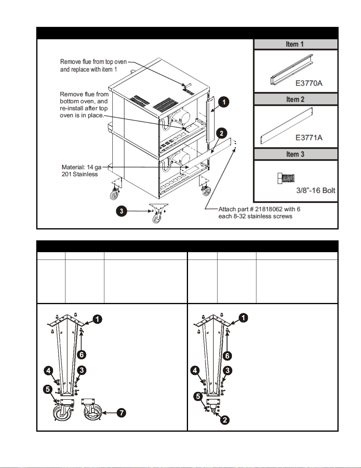
For a stack of two ovens: Refer to Figure 3
(1) Remove flue from top oven and replace with flue-adaptor supplied in the stacking kit.
(2) Tilt lower unit over to the left side and position two 6" legs on the right side (one for front and one for
back), secure in place by using 4 bolts (3/8-16) per leg. Tighten firmly.
(3) Using proper lifting equipment, lift up the left side of the unit and attach the other two legs in the
same way.
(4) Using the lifting equipment, raise the top oven to proper height and slide onto top of the bottom
oven. Line up sides and front and fasten to each other at the rear of the units by using a mounting
bracket supplied in the stacking kit.
To assemble an open rack stand: Refer to Figure 2
(1) Loosen 12 bolts (attaching 31” legs) slightly.
(2) Remove 4 inner bolts, 1 from each of the 4 legs, place top right angle and top left angle underneath
and tighten these 4 bolts.
(3) Insert “Open Rack Shelf” and tighten into place with eight 3/8-16 screws, washers and nuts.
(4) Position “Rack Supports” and tighten in place using 4 each of flat washers and 5/16-18 Hex Nuts.
C. INSTALLATION WITH CASTERS (OPTIONAL):
Four casters (two with wheel brakes) and the mounting hardware are packed and included in the
shipment if ordered. Install casters with wheel brakes on the front of the unit. Installation must conform
to UL 197: Electrical Supply Connections for Permanently Connected Appliances. It requires that
permanently connected appliances with casters be provided with a means for securing the appliance to
the building structure to limit the movement of the appliance.
Oven Restraint: When casters are installed on either a single or double unit, a fixed restraint must be
used to limit the movement of the appliance without depending on or transmitting stress to the electrical
conduit. The restraint (a heavy-gauge cable) should be attached to the rear legs of the oven on which
casters are mounted. If disconnection of the restraint is necessary, the restraint must be reconnected
after the oven has been repositioned in its permanent location. The appliance shall be installed using
flexible conduit.
D. LOCATION AND MINIMUM CLEARANCES:
Move the oven to its final location keeping the minimum clearance from the back of the oven to the wall.
This clearance is necessary for safe operation and to provide proper air flow.
MINIMUM CLEARANCES FROM COMBUSTIBLE AND NONCOMBUSTIBLE CONSTRUCTION
Under Ventilation Hood
RIGHT WALL 1"
LEFT WALL 1"
REAR WALL 3"
4
Suitable for installation on combustible floor when installed with legs or casters
provided.
CAUTION: Do not set the oven with its back flat against the wall. It will not
operate properly unless there is at least three inches breathing space behind the
oven
NOTICE:
Local codes regarding installation vary greatly from one area to
another. The National Fire Protection Association, Inc., states in it’s NFPA 96
latest edition that local codes are “authority having jurisdiction” when it comes to
requirements for installation of equipment. Therefore, installations should comply
with all local codes.
E. ELECTRICAL CONNECTION:
Install according to the spacing requirements listed in the installation section of this manual. We
strongly recommend having a competent professional install this equipment. A licensed electrician
should make the electrical connections and connect power to the unit. Local codes should always be
used when connecting these units to electrical power. In the absence of local codes, use the latest
version of the National Electrical Code.
Note: For supply connections use No. 6 AWG wires suitable for at least 90°C.
The oven, when installed, must be electrically grounded in accordance with local codes and/or the latest
edition of the National Electrical Code ANSI/NFPA No. 70 in the USA (Canadian Electrical Code CSA
Standard C22.1, Part 1 in Canada).
In Europe, the appliance must be connected by an earthen cable to all other units in the complete
installation and, thence, to an independent earth connection in compliance with EN 60335-1 and/or
local codes.
Electrical power is to be supplied to the oven(s) by means of hard wiring, which is to be performed by a
qualified licensed electrician.
a) Adequate means must be provided to limit the movement of the appliance without depending on
or transmitting stress to the electrical conduit.
b) The location(s) where restraining means are to be attached to the appliance shall be specified.
c) The appliance shall be installed using flexible conduit.
TSCO-E1, TSDCO-E1
Model KW Voltage Phase
Amps
Motor
-
50hz
Motor
-
60hz
Line 1 Line 2 Line 3 N
RPM
(Low)
RPM
(High)
RPM
(Low)
RPM
(High)
BCO-E,
GDCO-E
10.5
208
1
48
48
-
-
725
1425
850
1725
10.5
208
3
30
30
28
-
725
1425
850
1725
10.5
220
-
240
1
44
44
-
-
725
1425
850
1725
10.5
220
-
240
3
26
26
2
4
-
725
1425
850
1725
Each oven requires separate electrical connections
Normal factory connections are made for 208 V. A.C. or 208/240 V.A.C., 60 Hz.
This unit is provided with a permanently lubricated electric motor. A wiring diagram may be found on the
back of the service panel on the right-hand side and also in this manual.

5
F. FLUE CONNECTION VENTILATION:
Installation under ventilation hood (standard):
Local inspectors and ventilation specialists should be consulted so that the design and the installation of
the hood conform to local/municipal codes. In the U.K., follow ventilation requirements as detailed in
B.S. 5440.
NOTE: DO NOT PUT A DAMPER IN THE FLUE AND DO NOT CONNECT A BLOWER DIRECTLY
TO THE FLUE.
If the flue runs directly to the free air outside the building, use a wind deflector or a UL listed vent cap at
the end of the pipe. Termination of the vent must be at least two feet above the highest part of the roof
within ten feet. REF: AGACATALOG NO. Xh0474.
G. INITIAL CLEANING:
Always clean equipment thoroughly before first use. Clean the protective oil from the metal parts and
interior of baking chamber with a solution of washing soda or the other grease dissolving material.
H. SYSTEM CHECK- ROTARY CONTROL (standard):
(1) Open the oven door.
(2) Turn Selector Switch to “HI.” The green indicator light near Selector Switch and oven light will
illuminate.
(3) Close the door. Oven lights will go off and fan will run. Make sure fan is rotating clockwise
looking from front.
(4) Press Oven Light switch. Oven light will go on and will go off as switch is released.
(5) Turn the thermostat knob. The amber indicator light near the thermostat will illuminate and the
heating elements will come on.
(6) Turn the timer knob past 10 minutes and back to 2 minutes. At the end of 2 minutes the buzzer
will sound. Reset by turning to “0.” All settings below 10 minutes require turning past 10
minutes and then back to the time required.
(7) Open the oven doors. Oven lights will go on and elements and fan will go off.
(8) Turn Selector Switch to “Cool Down” position. The fan will run to cool down the oven.
(9) Turn Selector Switch to “0” position.
(10) Close the oven doors.
NOTE: WITH THE DOORS CLOSED, THE POWER SWITCH “ON” AND THE SELECTOR SWITCH
IS IN ANY POSITION OTHER THAN “0”, THE OVEN WILL START HEATING AS SOON AS THE
SET TEMPERATURE IS HIGHER THAN THE OVEN TEMPERATURE.
THERMOSTAT INDICATOR LIGHT GOES OUT WHEN OVEN REACHES SET TEMPERATURE AND
COMES ON WHEN OVEN IS HEATING UP.
IN THE EVENT OF POWER FAILURE, THE OVEN WILL NOT OPERATE.
PROGRAMMING MENUS: See Operating/Programming Instruction Booklet for
Programmable Oven Control with Bakers Pride Software for Cyclone Series
Convection Ovens supplied with this option.

6
II. OPERATING INSTRUCTIONS
A. GENERAL INSTRUCTIONS:
(1) This equipment has an Electronic Temperature Control.
(2) Due to increased efficiency of this oven, the temperature of standard recipes may be reduced
50°F (30°C).
(3) Always load each shelf evenly. Space pans away from each other and from sides and back of
oven to allow maximum air flow between them.
(4) Large tempered glass windows and interior lights allow a close check on the product making it
unnecessary to frequently open the doors. Products cook faster in a convection oven as
compared to a conventional oven. Depending on the product and the type of pans used, time
saving may run from 20 percent to as high as 50 percent.
B. OPERATION SEQUENCE ROTARY CONTROL:
Cook only rotary control:
(1) Close the oven doors.
(2) Turn Selector Switch to “HI” or “LO” position. The indicator light near the Selector Switch will be
illuminated.
(3) Turn the thermostat knob to the desired cooking temperature.
(4) Upon reaching the set temperature, the indicator light near the thermostat will go out.
(5) Load the oven with product to be cooked.
(6) Remove the product from the oven when done.
Timed cooking rotary control:
(1) Close the oven doors.
(2) Turn Selector Switch to “HI” or “LO” position. The indicator light near the Selector Switch will be
illuminated.
(3) Turn the thermostat knob to the desired cooking temperature.
(4) Upon reaching the set temperature, the indicator light near the thermostat will go out.
(5) Load the oven with product to be cooked.
(6) Turn the timer knob to the desired bake time and timer will start counting down.
(7) When timer reaches zero, a buzzer will sound.
(8) Turn the timer knob to “O” position.
(9) Remove the product from the oven.
NOTE: TIMER DOES NOT CONTROLTHE OVEN.
Cook and Hold Rotary Control:
(1) Close the oven doors.
(2) Turn Selector Switch to “HI” or “LO” position. The indicator light near the Selector Switch will be
illuminated.
(3) Turn the thermostat knob to the desired cooking temperature.
(4) Upon reaching the set temperature, the indicator light near the thermostat will go out.
(5) Load the oven with product to be cooked.
(6) Turn the timer knob to the desired bake time and timer will start counting down.
(7) When timer reaches zero, a buzzer will sound.
(8) Turn the Timer knob to “O” position.
(9) Turn the thermostat knob to the desired hold temperature.
(10) Remove the product from the oven when done.

7
Optional steam injection Rotary control:
The solenoid valve for steam injection is mounted behind the service panel on the right-hand side of the
unit. The electronic timer is preset at the factory. A ¼” copper tubing is provided on the Solenoid Valve
for water hookup with a compression fitting. After the water hookup is made, make sure that there are
no leaks. For steam injection, press the Steam switch momentarily.
NOTE: DO NOT USE STEAM INJECTION AT TEMPERATURES BELOW 275°F (135°C).
Oven cool down Rotary control:
To cool down the oven to a lower desired temperature, follow the steps detailed below.
(1) Open the oven doors.
(2) Turn Selector Switch to “oven cool down” position. Fan will now operate and cool down the
oven.
(3) When the oven has cooled down to the desired temperature, turn the Selector Switch to “O”
position. Close oven doors.

8
C. OPERATING/PROGRAMMING INSTRUCTIONS - COOK & HOLD-3 PLUSTM CONTROLLER
(For Convection Ovens: CO11-G, CO11-E, COCE, TSCO-E1 & TSDCO-E1)
When lit, denotes
HOUR/MINUTE timing
mode
When lit, denotes
MINUTES/SECONDS
timing mode
When lit, denotes
appliance is at ready
(set) temperature
When lit, oven is heating
to set temperature
When lit, a hold time has
been programmed for
the corresponding
product key
In “programming” mode
used to set a hold time
for corresponding
product key
In “operating” mode
shows actual
temperature when
pressed and held
In “programming” mode,
when lit, denotes this is
the key you are setting;
in “operating” mode
when lit, denotes this is
the active key.
In “programming” mode,
denotes this is the key
you are setting; in
“operating” mode used to
start a timing cycle
Used to start a timing
cycle
In “operating” and
“programming” mode
used to increase or
decrease the time
In “operating” and
“programming” mode
used to increase or
decrease the
temperature.
When lit steady,
denotes fan is set to
ON. When flashing,
denotes fan is set to
pulse for the corres-
ponding product key
In “programming”
mode, used to set the
fan option for
corresponding
product key
In “operating” mode
the manual button is
used for on-the-fly
change of time or
temperature
Used to stop a
timeing or hold time
cycle
This hidden key is
used to enter
“programming mode”.
Programmable
Controller
Stores three operator
programmed
standard recipes plus
one manual override
recipe that can be
adjusted at any time.
Rotary Power/Fan
Control
Features four
positions for every
essential operation
Low Fan, High Fan,
Cool Down and Off.
Oven Light
Momentary
Switch
Optional, Manual
Stream Injection
The electronic timer
is preset at the
factory (operator
adjustable)
CO11-G, CO11-E, COCE
TSCO-E1 & TSDCO-E1

9
OPERATING INSTRUCTIONS
There are 3 programmable times & temperatures, and 1 manual override time & temperature setting.
The timing range of all keys is from: 01 second to 99 hours (automatically switches from min/sec. to
hour/min). Each key is also programmable for one hold time and a two-position fan (on/pulse).
In normal operating mode, the READY LIGHT (LED) will illuminate when the oven temperature is +20°F
of set temperature. The HEAT LIGHT (LED) will illuminate when actual temperature is below set
temperature and the unit is calling for heat.
Once set and actual temperatures are equal, key 1, 2, 3 or M may be pressed. The light above the
corresponding key will be lit. Pressing the START key will begin a flex time countdown (time is
compensating) depending on temperature.
OPTIONAL STEAM INJECTION
The solenoid valve for steam injection is mounted behind the service panel on the right hand side of the
unit on COC-E and on back of the unit on C011 -E/G. The electronic timer is pre-set at the factory and
may be adjusted by operator if required for shorter or longer steam burst. For steam injection, press the
steam injection switch.
OVEN COOLDOWN
To cool down the oven to a lower desired temperature, follow the steps detailed below: Open the oven
door(s). Turn selector switch to "Oven Cool Down" position. Fan will now operate and cool down the
oven. When the oven has cooled to the desired temperature, turn the selector switch to the "0" position.
OPERATING NOTES
When the oven is turned on it will automatically preheat to set temperature if the door is closed. If the
door is opened while program is running, the cook cycle will pause and the display will flash. When the
door is closed, the display will return to the count down from where it was paused.
STARTING A COOK CYCLE
To start a cook cycle, simply turn selector switch to LO or HI position and press the product
key for the product you wish to cook. If the product key is programmed, the correct cooking
time will be displayed 12:00 (example). Press the START key and the time will immediately
start to count down in minutes and seconds. If: 00 is displayed immediately and the unit starts to signal,
the key being operated is not programmed. If correctly programmed, it will count down to :00. When
zero is reached, the light above the product key will be flashing, the controller will emit an audible alarm
and immediately begin counting up (if programmed for a hold time).
Cancel this alarm by pressing the stop key; controller will continue to count up.
HOLDING TIMERS
If the unit is programmed with a holding time, the holding time will automatically start counting upon
expiration of the cooking cycle. When there is an active hold time, the HOLD indicator will be lit and the
light above the product key with the hold time will be flashing.
To cancel, press the key.

10
DISPLAY DESCRIPTIONS
The unit is in the Operating Mode. The actual temperature is shown in the display and is
within 20 degrees of the programmed temperature.
The unit is in the Operating Mode. The actual temperature will flash in the display and is
more than 20 degrees below the programmed temperature range.
The unit is in the Operating Mode. The flashing display signifies a cook cycle has just been
completed.
The unit is in the Operating Mode. With three zeros displayed, the probe has failed, or the
appliance has gone beyond operating temperature. Shut the appliance OFF immediately
and call a technician.
CONTROLLER FEATURES
Fahrenheit or Celsius Temperature Display
The operator is allowed to configure the controller to display the temperature in degrees Fahrenheit or
Celsius from the jumper on the back of the circuit board (J3). By default, the unit is shipped from the
factory in Fahrenheit (J3 not shorted), unless otherwise specified by the customer. For Celsius display,
power unit down, remove jumper from Pin 1 and short both pins. When power is re-applied, the
controller will be in Celsius operation.
Programmable Times
The operator will have the ability to
program the cook times for each product
key. The controller is programmable in
minutes (up to 59) and seconds (up to
59), then hours (up to 99).
Programmable Temperatures
The operator will be able to program
cook temperatures for each product key.
The valid temperature range is 150 to
550°F (66 to 288°C).
Programmable Hold
The operator will be able to program each product key for a counting hold time and temperature
(140 to 200°F/60 to 94°C) or disable the hold mode.
HOLD LIGHT (LED) ON = hold mode enabled
HOLD LIGHT (LED) OFF = hold mode disabled.
Programmable Fan
The operator will be able to program each product key for one of two fan modes.
FAN LIGHT (LED) ON = Fan always ON
FAN LIGHT (LED) Flashing = Fan pulsed
Flashing Display
The temperature display will flash after every product key is pressed. The display will continue to flash
until the actual temperature is within 20°of set temperature.

11
Programming the Oven Controller
The following steps are needed to enter and program each of the product keys. Please note that you
must follow each of the steps below for each product key.
NOTE: The manual “M” key allows you to temporarily change the set temperature & time and will reset
to the original programming parameters after you are done cooking. This key is programmed the same
as keys 1, 2 & 3 except that programming mode does not have to be entered to do it. However, you can
still manually program the controller while in programming mode.
ACTION RESULT
Press the product key you want to
program.
The corresponding LED will
light above the selected
product key.
Enter the programming mode by pressing
and holding the area between the START
and STOP keys until the light above the
product key starts flashing (approx. 3
seconds).
You have successfully entered
the programming mode.
To set the cooking time, press the up and
down arrow key to the right of the display.
The longer you press the key,
the faster the display will
change.
To set the cooking temperature, press the
up and down arrow key to the right of the
temperature display.
The longer you press the key,
the faster the display will
change.
To select the hold feature and set the
holding temperature, press and hold the
HOLD key, then use the up or down arrow
to the right of the temperature display to
select your holding temperature.
This will activate the holding
feature and set the holding
temperature. NOTE: The light
above the HOLD key will be on
if you have set the hold feature
correctly.
To select the fan operation, press the FAN
key until the mode you want is displayed.
1. The light above the FAN
key is on, the fan will be ON
when door is closed.
2. The light above the FAN
key is flashing, the fan will
ONLY be ON when the heat
goes ON.
To exit the programming mode, press the
space between the START and STOP
keys.
The product key light will be on
steady, and the program will be
saved.
PORTIONS OF THIS INSTRUCTION MANUAL PERTAINING TO THE CH-100 CONTROLLER ARE
REPRINTED WITH THE PERMISSION OF FOOD AUTOMATION-SERVICE TECHNIQUES, INC.
(FAST). © 2001 Baker’s Pride Oven Co., Inc. All Rights Reserved.
IMPORTANT FOR FUTURE REFERENCE
Please complete this information and retain this manual for the life of the equipment. For Warranty
Service and/or Parts, this information is required.
Model Number Serial Number Date Purchased

12
D. CLEANING
Always clean equipment thoroughly before first use. Clean unit daily.
WARNING: To avoid any injury, turn the power switch off at the fuse disconnect
switch/circuit breaker or unplug the unit from the power source and allow to cool
completely before performing any maintenance or cleaning.
WARNING: Unit is not waterproof. To avoid electrical shock or personal injury,
DO NOT submerge in water. DO NOT operate if it has been submerged in water.
DO NOT clean the unit with a water jet. DO NOT steam clean or use excessive
water on the unit.
CAUTION:
Use mild detergent or soap solution for best results. Abrasive cleaners
could scratch the finish of your unit, marring it’s appearance and making it
susceptible to dirt accumulation. DO NOT use abrasive cleaners or
cleaners/sanitizers containing chlorine, iodine, ammonia or bromine chemicals as
these will deteriorate the stainless steel and glass material and shorten the life of
the unit. Use nylon scouring pads. DO NOT use steel wool.
OVEN INTERIOR:
Clean The Racks And Rack Support Guides:
Open the doors and remove all wire racks and rack support guides. Take them to the sink and thoroughly
clean in warm water with mild detergent or soap. Use a nylon scouring pad or stiff nylon brush.
DO NOT USE STEEL WOOL.
Clean The Stainless Steel Interior:
Baked on splatter, oil, grease or discoloration on the stainless steel inside of the oven may be removed
with stainless steel cleaner, or any other similar cleaning agent. NEVER use vinegar or any corrosive
cleaner. Use only cleaners approved for stainless steel. NEVER use cleaning solvents with a
hydrocarbon base. NEVER use a wire brush, steel or abrasive scouring pads, scraper, file or other steel
tools. NOTE: ALWAYS RUB THE STAINLESS STEEL ALONG THE GRAINS.
Clean The Blower Wheel:
To clean the blower wheel, remove and immerse in ammoniated water for 20 to 25 minutes. Then,
scrub it off with a small, stiff brush. The same procedure can be followed for wire racks and rack
supports. To remove the blower wheel, loosen the set screws (2) on the hub of the blower wheel and
tighten the 3/8” wheel puller bolt (supplied) in center of hub (See Fig. 1).
Clean The Porcelain Interior:
Porcelain enamel interiors are designed to be as maintenance free as possible. However, for best
results, the oven should be cleaned regularly. Enameled interiors can be easily cleaned with oven
cleaners. KEEP CLEANING FLUIDS AWAY FROM ELECTRICAL WIRES, LIGHT SOCKETS,
SWITCHES AND CONTROLPANEL.
OVEN EXTERIOR:
Clean The Exterior Stainless Steel:
To remove normal dirt or product residue from stainless steel, use ordinary soap and water (with or
without detergent) applied with a sponge or cloth. Dry thoroughly with a clean cloth. Never use vinegar
or corrosive cleaner. Do not use chorine based cleaners.
To remove grease and food splatter or condensed vapors that have baked on the equipment, apply
cleaners to a damp cloth or sponge and rub cleanser on the metal in the direction of the polished lines
on the metal. Rubbing cleanser as gently as possible in the direction of the polished lines will not mar
the finish of the stainless steel. To remove discoloration, use a non-abrasive cleaner. NEVER use a
wire brush, steel or abrasive scouring pads, scraper, file or other steel tools. NEVER RUB WITH
ACIRCULAR MOTION.

13
Figure 1 Cleaning The Blower Wheel
E. SERVICING:
NOTE: THIS APPLIANCE MUST BE SERVICED BY AN AUTHORIZED SERVICE AGENT.
(1) Power supply to the unit must be disconnected before any service is performed.
(2) Most of the service on the unit can be performed from the front and/or control panel side.
(3) For proper servicing, access to the control panel side of the unit will be required.
(4) It will be necessary to have access to the back of the oven for service needs related to the
electric power supply.
(5) A system wiring diagram is provided in this manual and on the back of the service panel on the
right side of the oven.
(6) All servicing should be performed by a factory-authorized technician only.
(7) For proper maintenance and repairs, call the factory toll free (800-431-2745) for an authorized
service agency in your area.
WARNING: RISK OF FIRE. When stacked two high maximum, use stacking kit !
part # E3771A only.
CAUTION: This product, when stacked, has more than one power-supply!
connection point. Disconnect all power supplies before servicing.
Figure 2 OPEN RACK STAND ASSEMBLY INSTRUCTIONS: TSCO-E1 & TSDCO-E1
Assembly Instruction
1. Place undershelf (6) between legs & secure with 1 1/4-20
UNC screws (4), flat washers (3) & 2 locknuts (2). The holes
for mounting the wire racks should be toward the front of the
oven.
2. Place open rack supports (1) between legs & secure with
1/4-20 UNC screws (4), flat washers (3) & locknuts (2).
3. Slide wire rack supports (5) into position using the holes
in the undershelf (6) as a guide.
Item P/N Description Quan
1 21818232 Support, Open Rack 2
2 770504 Lock Nut 1/4-20 12
3 8519600 Washer, Flat 1/4” 12
4 8208200 Screw, 1/4-20 x 3/4” 12
5 21816807 Support, Wire Rack 2
6 21818220 Undershelf, Gas Oven 1
14
Figure 3STACKING INSTRUCTIONS FOR: TSCO-E1 & TSDCO-E1 CONVECTION OVENS
Figure 4 LEG ASSEMBLY INSTRUCTIONS - MODEL:TSCO-E1 & TSDCO-E1
Item P/N Description Item P/N Description
1
2
3
4
5
6
7
21796810
8633102
8227700
8509300
8435000
82447-00
8633101
Weldment, Oven Leg
Caster, 5” Swivel W/Top Plate
Hex Hd 5/16-18 X ¾ Bolt #5 Zn
Washer, Flat SAE, 5/16
Hex-nut 5/16-18
Hex Hd. 3/8-16 X .750 #5
Caster, 5” Swivel W/Plate & Brake
1
2
3
4
5
6
21796810
8633515
8227700
8509300
8435000
82447-00
Weldment, Oven Leg
Foot Insert, Adjustable
Hex Hd 5/16-18 X ¾ Bolt #5 Zn
Washer, Flat SAE, 5/16
Hex-nut 5/16-18
Hex Hd. 3/8-16 X .750 #5
1. Attach two item 2 to two item 1 using
item 3, 4 and 5.
2. Attach two item 7 to two item 1 using
item 3, 4 and 5.
3. Using proper lifting equipment attach
item 1 to the corresponding hole
patterns located in the bottom of the
oven with item 6.
1. Attach four item 2 to four item 1 using
item 3, 4 and 5.
2. Using proper lifting equipment attach
item 1 to the corresponding hole
patterns located in the bottom of the
oven with item 6.
15
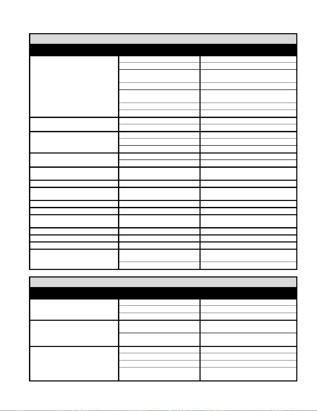
HELPFUL HINTS
PROBLEM CAUSE SOLUTION
Food browns unevenly
Improper heating temperature.
Preheat until desired temperature is reached.
Aluminum foil on rack or oven bottom.
Remove foil.
Several pans cr
owded together.
Center pans on racks, or leave more space
between all pans and oven walls.
Baking pans too large.
Use smaller pan.
Baking pan dark or glass.
Lower oven temperature 25°F (
-
3.8°C) for this
type of pan.
Temperature too low
Increase tempe
rature
Time too short
Increase bake time
Food dries before browning
Oven temperature too high
Lower oven temperature
Oven door opened too frequently
Check food a minimum number of times.
Cookies too brown
Oven temperature too high
Lower oven temperat
ure
Dark cookie sheet
Use light, shiny cookie sheet.
Pans too deep
Use a cookie sheet (not a baking pan).
Cookies too flat
Hot cookie sheet
Allow cookie sheet to cool between batches.
Fan is set on High Speed
Set fan to Low Speed
Cake too brown on
bottom or crust forms on
bottom
Oven temperature too high.
Lower temperature; if using glass or dark pan,
lower 25°F (-3.8°C)
Cakes have light outer color
Thermostat set too low.
Raise temperature
Cake settles slightly in the center.
Bake time too shor
t or bake
temperature too low.
Bake longer or raise oven temperature slightly.
Do not open doors to oven for long periods.
Cake ripples
Overloading pans or batter is too thin
Reduce pan loads. Thicken batter.
Cakes are too coarse
Thermostat set too high.
Lower oven temperature.
Pies have uneven color
Too many pies per rack.
Reduce number of pies per rack or eliminate
use of bake pans.
Cupcakes crack on top
Thermostat set too high.
Lower oven temperature.
Meats are browned not done in the center
Therm
ostat set too high.
Lower oven temperature and roast longer.
Meats are well done and not browned
Thermostat set too low.
Raise temperature. Limit amount of moisture.
Meats develop hard crust
Thermostat set too high.
Reduce temperature or place pan of wat
er in
oven
Fan is set on High Speed
Set fan to Low Speed
TROUBLESHOOTING CHART
PROBLEM CAUSE SOLUTION
No heat
Oven has no electrical power
Check electrical supply.
Power switch on control panel is off.
Set the control panel to COOK or OVEN ON
.
Doors are open.
Close doors.
Oven does not come to ready.
The oven has not reached preheat
temperature. Wait for oven to reach preheat temperature.
Internal problem with main temperature
control.
Call Bakers Pride factory authorized service
center
Convection fan does not run.
Oven has no electrical power.
Check electrical supply.
Circuit breaker tripped.
Reset the breaker.
Doors are open
Close doors.
Door switch
Call Bakers Pride factory authorized service
center
16
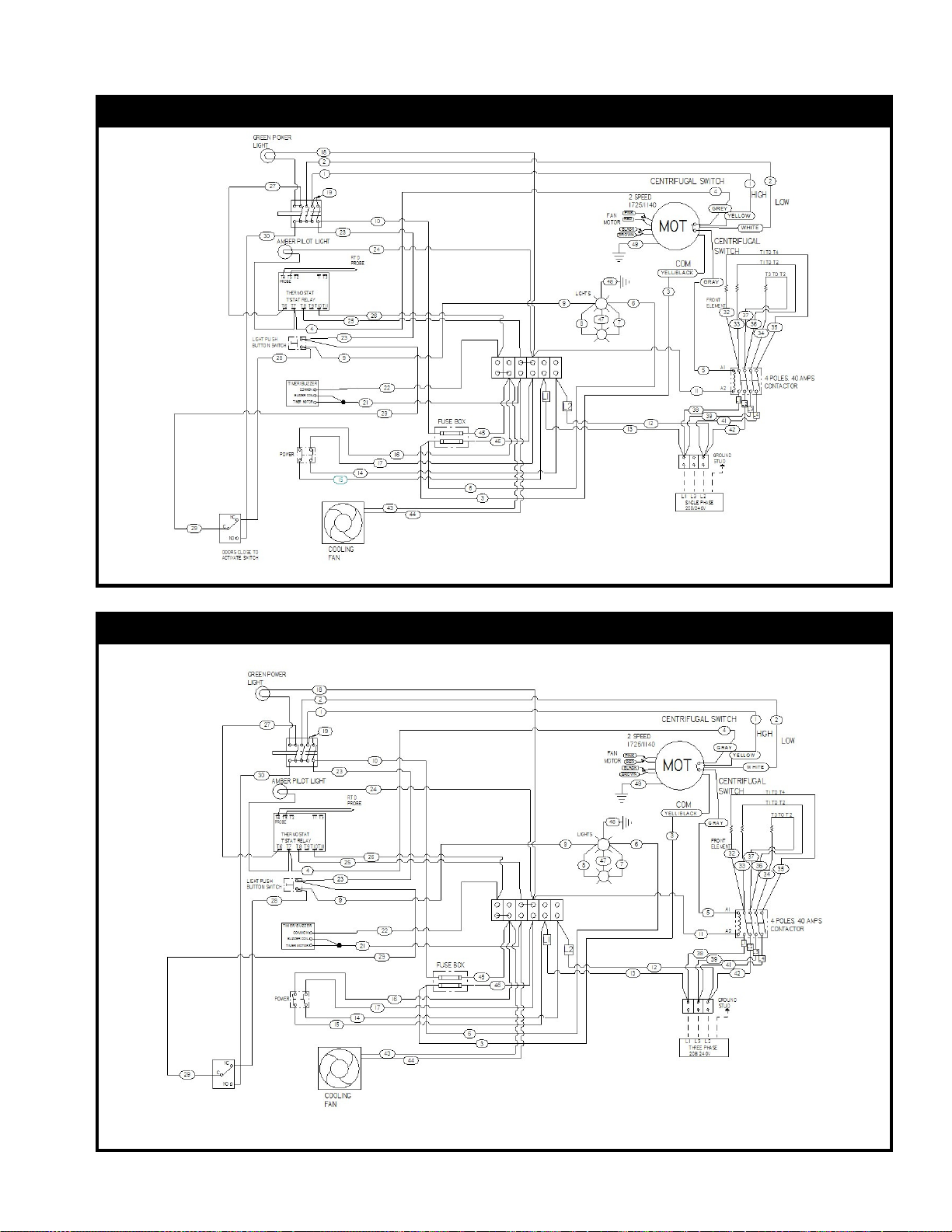
F. Wiring Diagram – TSCO-E1 & TSDCO-E1 208V/240V, 1 Phase (Dial Control)
P/N 8806675
Wiring Diagram – TSCO-E1 & TSDCO-E1 208V/240V, 3 Phase (Dial Control)
P/N 8806674
17
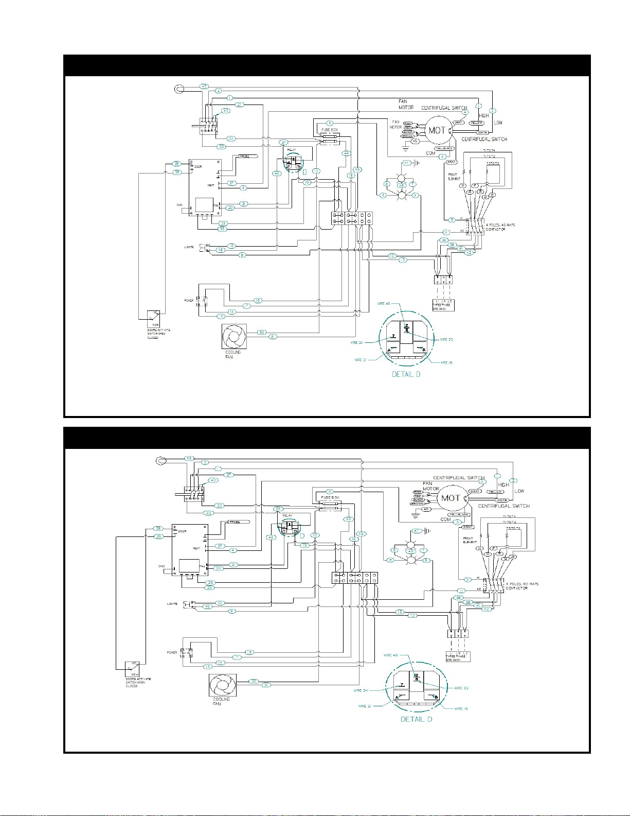
Wiring Diagram – TSDCO-E1 208V/240V, 1 Phase (Push-Button Control)
P/N 8806677
Wiring Diagram – TSDCO-E1 208V/240V, 3 Phase (Push-Button Control)
P/N 8806678
18
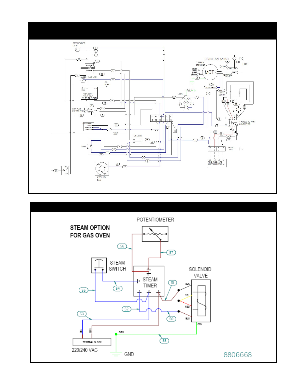
Wiring Diagram–TSCO-E1 & TSDCO-E1 230V/400V,3 Phase,4 Wire(Dial Control)-
EXPORT
P/N 8806676
STEAM INJECTION WIRING DIAGRAM 220V/240V 02/11/10 REV -

19
NOTES: ___________________________________________________________________________
__________________________________________________________________________________
__________________________________________________________________________________
__________________________________________________________________________________
__________________________________________________________________________________
__________________________________________________________________________________
__________________________________________________________________________________
__________________________________________________________________________________
__________________________________________________________________________________
__________________________________________________________________________________
__________________________________________________________________________________
__________________________________________________________________________________
__________________________________________________________________________________
__________________________________________________________________________________
__________________________________________________________________________________
__________________________________________________________________________________
__________________________________________________________________________________
__________________________________________________________________________________
__________________________________________________________________________________
__________________________________________________________________________________
__________________________________________________________________________________
__________________________________________________________________________________
__________________________________________________________________________________
__________________________________________________________________________________
__________________________________________________________________________________
__________________________________________________________________________________
__________________________________________________________________________________
__________________________________________________________________________________
__________________________________________________________________________________
__________________________________________________________________________________
__________________________________________________________________________________
__________________________________________________________________________________
__________________________________________________________________________________
__________________________________________________________________________________
__________________________________________________________________________________
__________________________________________________________________________________
__________________________________________________________________________________
20
TRI-STAR TERMS OF SALE & LIMITED WARRANTY FOR U.S.A. INSTALLATION
TERMS - 1%-10 days, n/30 days subject to credit approval. All accounts past due are subject to 1-1/2% per month service charge.
FOB - actory / Santa Ana, CA 92707
PRICES - Prices are subject to change without notice. Prices do not include sales tax. All prices are in U.S. Dollars.
POSSESSION - of this price list does not constitute an agreement or an offer to sell.
NOTE - The company reserves the right, without prior notice, to make changes and revisions in product specifications, design and
material; which in the opinion of the company will provide greater performance, efficiency, and durability.
SHIPMENTS - The Company's responsibility ceases with delivery of goods to the transportation company after receiving a receipt
for them in "Good Order". In case of freight damage, do not refuse shipment, but call agents attention to its condition and make a
careful note of details on freight bill before charges are paid. In case of concealed damages, immediately notify freight agent in
writing (retaining a duplicate copy) notifying them of your intention to file claim, so that they may inspect shipment and provide
necessary forms for filing claim. Retain all packaging and do not remove from delivery site.
RETURNED GOODS - Returned goods are subject to a 20% restocking charge and the cost of reconditioning. Prior to shipping, a
Return Goods Authorization (RA) number must be granted by Tri-Star all returned goods must be shipped freight prepaid.
Shipments without RA number will be refused. Custom units built to buyer specifications may not be returned or canceled.
LIMITED WARRANTY
TRI-STAR warrants its new Product (s) to be free from defects in material and workmanship for a period of one (1) year from the
original date of installation not to exceed 18 months from date of shipment from our factory. Equipment sold and installed for
residential use, or outside the continental United States is excluded from this warranty.
This warranty is limited to Product(s) sold to the original commercial user. The liability of TRI-STAR is limited to, at TRI-STAR's
option, the repair or replacement of any part found by TRI-STAR to be warranted herein. TRI-STAR shall bear the normal labor
charges for repair of replacement to the extent that such repair or replacement is performed within 35 miles of the office of an
authorized service agency, within the continental United States and during regular (straight time) hours. Travel outside of the 35
miles and any work performed at overtime or weekend rates would be the responsibility of the owner/user. Defective parts must
be returned to TRI-STAR, fright prepaid, for Warranty Inspection.
TRI-STAR assumes no responsibility for any product not installed properly in accordance with the instructions supplied with the
equipment. Any equipment which has been modified by unauthorized personnel or changed from our original design is not
covered under this Warranty. urthermore, TRI-STAR assumes no obligation for any product which has been subject to misuse,
abuse or harsh chemicals. Normal maintenance as outlined in the instructions is the responsibility of the owner-user and is not a
part of this warranty. * Ninety days on Cast Iron Parts.
Light bulbs, porcelain, and glass components are excluded from this warranty.
ryers: one year parts and labor, Limited Warranty on the fry tank: 5 years, prorated on stainless steel fry tank. Normal parts wear
and maintenance is also not covered by this warranty. This warranty is in lieu of any other agreement, expressed or implied, and
constitutes the only warranty of TRI-STAR with respect to the products.
This states the exclusive remedy against TRI-STAR relating to the product(s) whether in contract or in tort or under any other legal,
theory, and whether arising out of warranties, representations, instruction, installation or defects from any cause.
TRI-STAR shall not be liable whether in contract or in tort or under any other legal theory, for loss of revenue or profit, or for any
substitute use or performance, or for incidental, indirect, special or consequential damages, or for any other loss or cost of similar
type.
Proper installation, initial check out, air shutter adjustments, or normal maintenance such as lubrication, adjustment or calibration
of controls is the responsibility of the dealer, owner-user or installing contractor and is not covered by this warranty.
Prices listed in this catalog are in U.S. Dollars. All Prices are subject to change without prior notification. TRI-STAR is not responsible for
printing errors in pricing or specifications.
This manual suits for next models
5
Table of contents
Popular Convection Oven manuals by other brands

Buffalo
Buffalo CC038 instruction manual

Alto-Shaam
Alto-Shaam PLATINUM Series Installation operation & maintenance

Alto-Shaam
Alto-Shaam ASC-4E Series Specification sheet

Heat & Glo
Heat & Glo Patio Gourmet PGE-24-S3 Operating and assembly instructions

EUROPRO
EUROPRO TO21 owner's manual

EUROPRO
EUROPRO TO36 owner's manual

Alto-Shaam
Alto-Shaam 2-ASC-2E/STK Specification sheet

Casselin
Casselin CFCV1 user manual

Aroma
Aroma AeroMatic AST-910 Instruction manual & recipe guide

Blodgett
Blodgett SC-10E Installation operating and maintenance istructions

Blodgett
Blodgett ZEPHAIRE-240E PLUS Installation operation & maintenance

Black & Decker
Black & Decker TO2050S-MX use and care manual


