Star Trac Fitness E-ST 5090 User manual

Star Trac Fitness™
E-ST 5090 Stepper
Install Guide

STAR TRAC E-ST STEPPER Install Guide
E-ST 5090
E Series Stepper

STAR TRAC E-ST STEPPER Install Guide
ASSEMBLY AND SET P
The following parts are included with the base STAR TRAC E-ST STEPPER:
Description Qty Description Qty
Base 1 Screw, 1/4-20 x 1.25, Hex Head4
Display Weldment with Neck Assembly 1 Washer, 1/4 ID Type B, Flat 4
Handrails (1 Right, 1 Left) 2 Screw, 1/4-28 x 1/2, Button Head 4
Screw, .312-18 x 1.00, Hex Head 4
Washer, .312 Split Lock 4
Washer, .312 Flat 4
Nut, .312-18, Hex Machine 4
NOTE: The Di play A embly i found in it own box, along with the unit’ detailed operating in truction .
NPACKING AND ASSEMBLY
NOTE: Inspect the shipping carton for any parts that may be missing BEFORE discarding the carton. Items can shift during trans-
portation, and may be accidentally discarded with the carton. If any parts are missing, please contact Star Trac Support at 800-503-
1221. Have the serial number of the STAR TRAC E-ST STEPPER, and the part num-
ber(s) of the missing parts ready so they may be shipped to you.
1. npack the Shipping Carton
Open the top of the STAR TRAC E-ST STEPPER box, remove the
handrails and place aside. Remove the Display weldment/Next assem-
bly and place aside. Remove the fasteners and place aside. Remove
remaining packing material, and carefully remove from the pallet base.
Note: The display comes in a seperate box.
2. Removing the Shrouds
Remove the 6 screws that hold on the center shroud in place.
Next remove the 6 screws that hold the side shrouds in place.
Remove the side shrouds from frame. Set the 3 shrouds and
12 screws aside for later use.

STARTRACE‐STSTEPPER
Install Guide
3. InstallingtheDisplayWeldment/NeckAssembly
(a)AligntheDisplayWeldmentwiththebase.Usingthepre‐installed
wirepulltheMainI/Ocable(largewhiteplasticconnector),power
harness(smallwhiteplasticconnector),andcoaxialcable(black
rubbercover)fromthebottomthroughthetopoftheneckformating
tothedisplayasneeded.Itisrecommendedthateachwirebepulled
throughtheneckoneatatime.Takecaretoavoidunnecessary
tensionorbendingofthecables.IfthebasewillbematedwithanLED
displaywithoutaPVSkititisrecommendedtotuckthepowerharness
andcoaxialcableinsidetheneckastheywon’tbeused.
(b)Installthe4boltswiththeassociatedflatwashers,lockwashers,
andnutsasshown.Makesuretheboltsaretight.AftertheNeck
Assemblyhasbeenboltedinplace,youcanreplacetheshroudsthat
wereremovedaspartofStep2above.
4. OpenDisplay
Remove(2)M4x0.7screwsfrombackofdisplay(retainforlateruse)
witha#2Phillipsscrewdriverandseparatethebackofthedisplay
fromthefront.
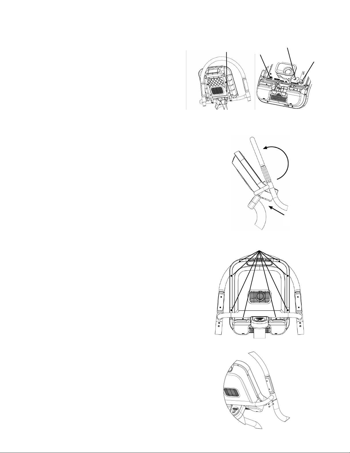
5. InstallingtheDisplayAssembly
(a)Takethereardisplaycoverandattachittothedisplayweldment
usingthesuppliedscrews.NotethattheNeckAssemblyhasbeen
hiddentoshowtheimportantdetailbutwillalreadybeattached.
ScrewsM4x0.7
(a) (b)
Pre
‐
installed wire
MainI/Ocable
CoaxCable
PowerHarness
STAR TRAC E-ST STEPPER Install Guide
(b) It is now time to attach the display. NOTE: Thi tep
a ume that you will be attaching the LED di play. Should you
be in talling the embedded di play or adding a PVS kit, plea e
refer to tho e applicable manual . The following display con-
nections will need to be made: connect the main display cable
to the connector labeled J4 on the display PCB, connect the
heart rate grip cable to the heart rate board, and connect the
ground wire from the heart rate board to the quick disconnect
tab on the display weldment.
(c) With the display electrical connections made, you can now
attach the display. There are 2 tabs located on the bottom of the
display weldment, so in order to attach the display, you will first
need to guide the bottom of the display under the tabs and then
second you will need pivot the display forward around the tabs to
mate the display to the rear plastics. Once in place, you can attach
the screws.
(d) With the display in place, attach the 8 M4 x 0.7 screws provided.
6 screws go around the rear of the display and 2 go near the under-
side of the cupholders as shown.
5. Installing the Handrails
NOTE: It i recommended that thi tep be performed by at lea t 2 people.
(a) With the assistance of another person, tip the STAR TRAC E-ST STEP-
PER forward and hold in place while completing the following steps.
(b) Remove the 2 rear leg levelers.
(c) Slide the left handrail into the upper end of the left handlebar
weldment and line up the screw holes.
(d) Loosely attach 2 supplied button head screws to the left handlebar
weldment junction using a 5/32” (4mm) hex key or T-handle.
Board
1ST
2ND
J4
round Wire
Heart Rate
Board
Quick Disconnect
M4 x 0.7
Screws

(e) Position the lower end of the left handrail over the rear leg weldment, then pulling the
handrail towards you secure it into position with 2 washers and 2 hex screws provided using
a 5/32” (4mm) hex key or T-handle.
(f) Tighten the button head screws from step d above.
(g) Repeat steps c - f for the right handrail.
(h) Replace the 2 leg levelers that were removed in step b.
(i) Return the STAR TRAC E-ST STEPPER to the upright position.
6. Final Assembly and Testing
Check all screws to ensure they are tightened securely.
Adjust leveling feet to assure that the Stepper is level to the floor and does not rock back and forth.
Make sure the side handrails are tight.
Mount the Stepper, begin stepping, and verify that the display panel turns on.
Operate the unit to check for proper operation.
You have now completed assembly of your STAR TRAC E-ST STEPPER.
STAR TRAC E-ST STEPPER Install Guide
Other manuals for Fitness E-ST 5090
1
This manual suits for next models
1
Table of contents
Other Star Trac Stepper Machine manuals


