StarBand StarBand Satellite System User manual
MobileInternetSatellite.com
StarBand® Remote Installation
September 2013

© 2004-2013, MobileInternetSatellite.com

MobileInternetSatellite.com
StarBand® Remote Installation
Version 2.6


© 2004-2013, MobileInternetSatellite.com Table of Contents i
Table of Contents
StarBand® Remote Installation Guide
Introduction 2
Getting the Cables to the Modem 3
Step 1 – Unpacking the Boxes & Checking the Contents 4
Step 2 – Getting the Pointing Parameters & Programming the Meter 5
BirDog Alternatives 5
Getting the Pointing Parameters with the Point Dish Utility 6
Programming the BirDog or First Strike Meter 7
Step 3 – Assembling the Feed Arm & Setting Polarity to Horizontal 8
Assembling the Feed Arm 8
Installing the Alternate Transmitter 10
Comparing the Two LNB Options 11
Why Is a TRF Needed? 11
Changing the Polarity to Horizontal 12
Step 4 – Assembling the Tripod, Hardware Set, & Offset Adapter 14
Installing the Stanley Keeper (SK) - (May Be Pre-installed) 14
Assembling the Hardware Set - (May Be Pre-installed) 15
Using Your Tripod 16
Orienting the Tripod and Checking for a Plumb Mast 17
Attaching the Bubble Level 18
Step 5 – Putting the Dish Assembly Together 19
Modifying the Elevation Jack Screw - Replacing the Nut and Bolt With Knobs 19
Modifying the Elevation Jack Screw 20
Putting the AZ/EL Skew Cap Mount on the Dish & the Dish on the Mast 21
Adjusting the Elevation 22
Adjusting the Skew or Polarization Setting 23
Step 6 – Attaching the Feed Arm & Adding the Pigtail Cables 24
Assembling the GCD Adapter - Nova 1500 with Linear Transmitter Only! 25
Step 7 – Pointing the Antenna & Checking Your Alignment 26
Using a Satellite Meter 27
Connecting to the Modem 28
Using SkyManage to Point the Dish 29
Step 8 – Checking Your Alignment with CVACS 30
Troubleshooting Hints 31
Only 3 Lights on Modem ON 32
Only 1 Light on Modem ON 32

ii Table of Contents © 2004-2013, MobileInternetSatellite.com

BJ Consul
© 2004-2013, MobileInternetSatellite.com MobileInternetSatellite.com 1
MobileInternetSatellite.com
StarBand®Remote Installation Guide

2StarBand® Remote Installation Guide © 2004-2013, MobileInternetSatellite.com
Introduction
The objective of this document is to provide some easy guidelines and instructions for
assembling your StarBand satellite system and mobility kit. Of course, you should
always feel free to call, if you have questions.
The following tasks will be described in this document:
Step 1 Unpack your boxes and check the contents.
Step 2 Get the pointing parameters and program the meter.
Step 3 If not done, assemble the feed arm and set the polarity to horizontal.
Step 4 Set up the tripod, offset and hardware set.
Step 5 Put the mount on the dish and the dish on the mast. Set the skew and elevation.
Step 6 Attach feed arm to dish and attach the pigtail cables.
Step 7 Point the dish with a BirDog, First Strike or SkyManage.
Step 8 Check your alignment with CVACS.
Before we look at these steps in detail, let’s first cover a task that should be dealt
with first: getting the cables to the modem. This document will finish with some
troubleshooting hints.

© 2004-2013, MobileInternetSatellite.com StarBand® Remote Installation Guide 3
Getting the Cables to the Modem
You need to think about how the cables that come from the satellite dish outside will
connect to the satellite modem, which is typically inside.
Shown above is the most common method of solving this problem. Here is a
description of the dish-to-modem path:
1The short pigtail cables (1) are attached to the LNB at the end of the arm (blue
cable) and to the transmitter (red cable).
2They connect to the standard 50’ length of coax (3) using barrel connectors (2).
3The other end of the 50’ length of coax is typically connected to a dual exterior
coax connector (4), which is installed on the side of the RV. Two 1/2” holes are
drilled in the side of the RV for the installation.
4The short inside cables (5) are connected to the back of the dual exterior coax
connector (4) at one end, and to the modem (6) at the other end.
Although the above describes the most common installation, other approaches are
possible. For example, some mobile users prefer to put the modem and a wireless
router in a basement compartment, thus avoiding the need to drill holes in the RV.
Similarly, the modem and router could be place in a utility trailer, with easy access
for cables. In both possibilities, the user will connect from within the RV via Wi-Fi.
4StarBand® Remote Installation Guide © 2004-2013, MobileInternetSatellite.com
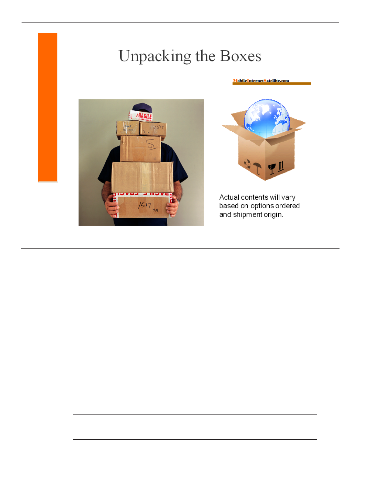
Step 1 – Unpacking the Boxes & Checking the Contents
The exact number of boxes and the contents of each box can vary, based upon the
current stock of boxes and from where the different items ship. However, the
complete contents of all boxes will be largely the same, with a couple of exceptions:
• Mobility kit - There will be either no meter, a First Strike meter, or a BirDog meter.
There will be either a liquid-filled lensatic or a Suunto tandem compass.
• Special order or omitted items - Obviously, any additional items ordered or any
items not wanted will affect the complete contents.
Here is the list of items:
• StarBand Satellite System: This includes the modem, dish, feed arm, and dual
coaxial cable.
• Tripod Assembly: Tripod, offset adapter, adapter hardware, and ballast strap.
• Tools: Optional meter, compass, level, CDROM, and setup card.
Note If you receive a very short serial cable (about 5” long), discard it. It is not
used for StarBand services, but is often included in the shipment anyway.

© 2004-2013, MobileInternetSatellite.com StarBand® Remote Installation Guide 5
Step 2 – Getting the Pointing Parameters & Programming the Meter
There are a couple of things you need to do first, in preparation for assembling your
equipment and setting it up for the first time:
• Getting the Pointing Parameters - You can do this any time, but you should do it
before you begin your setup. Knowing the direction of the satellite (azimuth) and
its elevation will help you pick a good RV site.
• Programming the Meter - If you have a BirDog or First Strike satellite meter, you
will need to program it with the satellite profiles you will be using.
These two things will be described in more detail later.
BirDog Alternatives
Pictured above are the BirDog and First Strike satellite meters.
Another alternative is to use the SkyManage Telemetry page, which provides the
received signal strength. The signal strength display will “go green” when you
point at the satellite.
These things are discussed in more detail later.

6StarBand® Remote Installation Guide © 2004-2013, MobileInternetSatellite.com
Getting the Pointing Parameters with the Point Dish Utility
You will use the Point Dish utility to determine the pointing parameters for your
current location, by zip code or longitude and latitude.
Use the following steps and the Point Dish utility, to determine the angle of elevation,
magnetic azimuth, and the skew/polarity settings for your location:
1Type 121 or 123 in the popup menu field, where the satellite is selected. Hit
Enter. Most assignments for mobile users will be on 121 W.
2Select and enter either the zip code or the longitude and latitude. Hit Enter.
3Click Calculate. Write down the values returned.
You will use this information to look for a good line of sight, when you are setting up.
You will set up the tripod, with one leg pointing in the magnetic azimuth direction.
Note You can also use a First Strike meter to get your pointing parameters. But,
you will need to mathematically adjust the azimuth and skew. How to do this is
described in the document called FirstStrikeSatelliteMeter.pdf.

© 2004-2013, MobileInternetSatellite.com StarBand® Remote Installation Guide 7
Programming the BirDog or First Strike Meter
Your BirDog meter comes pre-programmed for HughesNet. This means that if your
dealer or installer didn’t re-program it, you will need to upload a new configuration file
to your BirDog meter. You must first go to the BirDog web site and select the satellites
you want and then generate and download the configuration file. Then, you need to
upload the file to your BirDog.
Full details about how to program and use your BirDog meter are in the document
called BirDogSatelliteMeter.pdf.
If you have a First Strike meter and it isn’t already programmed for Echostar 9, at
121 W, the following parameters need to be configured:
• L = 121.0 W
• F = 12074
• SR = 21650
• LO = 10750
• LNB = 13
• 22 KHz should be blank
For details, see the document FirstStrikeSatelliteMeter.pdf.

8StarBand® Remote Installation Guide © 2004-2013, MobileInternetSatellite.com
Step 3 – Assembling the Feed Arm & Setting Polarity to Horizontal
If your feed arm did not arrive pre-assembled, use the following procedure to
assemble your feed arm. The polarity will be set to horizontal later.
The following tools are needed:
• 1/4” nut driver or common screw driver
• 10 mm wrench
• Philips screwdriver
Unpack the parts:
• The empty arm is packed with the dish.
• The feed horn assembly, the LNB, and the transmitter are usually boxed together.
Assembling the Feed Arm
1FigureA shows the Feed Horn/LNB assembly installed on the arm. Note the two
hex head sheet metal screws near the end of the arm, at the top of this photo and
in Figure B. These screws can be installed either before or after the feedhorn is
attached to the arm.

© 2004-2013, MobileInternetSatellite.com StarBand® Remote Installation Guide 9
2Remove the bolt, washers, and nut from the feed arm end near the two hex head
screws.
3Slide the Feed Horn/LNB assembly onto the arm so that the slotted tabs on the
radio mount flange mate with the two hex head screws (Figure B). Do not tighten
the hex head screws yet.
4Place the nut you removed into the nut pocket (Figure C) in the large cast part
that is now covering the bolt hole in the arm and feed the bolt through the hole
in the arm that is on the same side of the arm as the two hex head screws, and
turn the bolt to engage the nut. When the nut is engaged, tighten the bolt. Then
tighten the hex head screws.
Caution Caution! Do not over-tighten the hex head screws. Tighten only until the
resistance changes to where you are confident that they are gripping the casting.
5Bolt the radio to the radio flange using the 4 Phillips head screws packed in the
box with the radio. Critical: The “O” ring (Figure D) is packed in the bag with
the radio. It must be in place! If the “O” ring is damaged, a hardware store should
be able to provide the same size. While the assembly will work without the “O”
ring, it may take on moisture and cause serious internal damage to the wave
guide and feed horn.
6The fully assembled unit is shown in the larger photo.
The unit is normally shipped in a vertical transmit/horizontal receive configuration.
Current StarBand assignments are just the reverse: horizontal transmit/vertical
receive. How to change the polarity for horizontal transmit will be covered later.
Note If you have a Nova 1500 account, you might get a 2-watt transmitter and an
extra piece, called the BUC GCDAdapter. The steps for proper assembly of this are
described later in this document, when they are most easily performed.

10 StarBand® Remote Installation Guide © 2004-2013, MobileInternetSatellite.com
Installing the Alternate Transmitter
Spacenet/StarBand began shipping a new version of the transmitter (ODU). The
new transmitter is interchangeable with previous ODUs.You may get either version
of transmitter for either the 1- or 2-watt transmitters.
TheAN7042 is a Dual Mode Compact BUC (Block Up Converter). It is capable of
operating in SkyEdge II networks, as well as previous Spacenet platforms,
including the SkyEdge environment that StarBand uses.
The new transmitter is smaller in size than previous ODUs (see figures above, on
the left). It has a magnetic switch, which is used to change its function from
SkyEdge (or other legacy Spacenet equipment) to SkyEdge II.
This is indicated on the BUC as SE and SEII (see the graphic on the right). You
must use the SE (SkyEdge) setting for StarBand Nova modems.
The switch will normally be in the SE position when shipped, but please check its
position prior to installing. Attempting to bring the modem online with the switch
in the wrong position will not allow it to go online.
Note A comparison between the two different LNB options is covered next.
© 2004-2013, MobileInternetSatellite.com StarBand® Remote Installation Guide 11
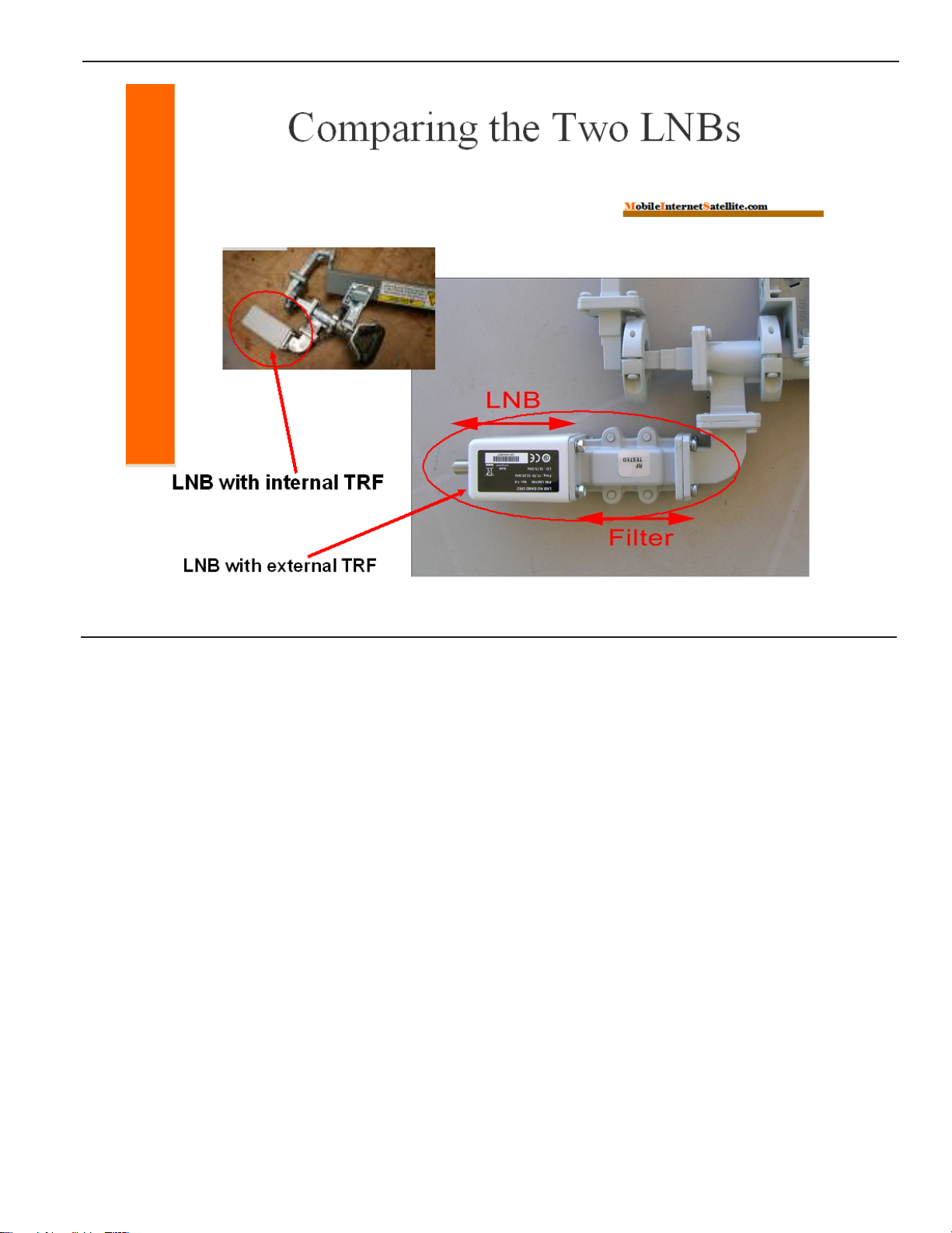
Comparing the Two LNB Options
Some older StarBand equipment used an LNB model that did not have an internal
Transmit Reject Filter (TRF). This meant that an external TRF was required. Later,
they moved to LNB models that included an internal TRF.
In July, 2010, StarBand again began using a model without an internal TRF. The
current model LNB is P/N LN2190.A separate TRF component will be mincluded
with the feedhorn assembly. You could receive either LNB model.
The TRF sits between the LNB and the feed horn assembly, as shown on the right,
above. On the left, you can see an LNB with an internal TRF. This LNB is longer
than the LNB with an external TRF.
Why Is a TRF Needed?
The purpose of the TRF is to prevent the energy coming from the transmitter, from
interfering with the received signal that is down converted by the LNB.
Without a TRF, the modem will often experience problems with losing the SYN
light on their modem, and possibly the Rx light as well.
If you use the longer LNB with an internal TRF and an external TRF, the received
signal can be significantly weakened! In this case, you can simply remove the
external TRF.

12 StarBand® Remote Installation Guide © 2004-2013, MobileInternetSatellite.com
Changing the Polarity to Horizontal
If you do not receive the feed arm pre-assembled, the feedhorn will be set to vertical
polarity for shipping, because this is how it fits in the box. However, since all current
StarBandassignmentson both 121and123 arehorizontal,itwill benecessaryto change
the transmit polarity setting from vertical to horizontal.
If your arm was shipped pre-assembled, it will already be set for the correct polarity.
The larger photo above illustrates the polarity, when set to vertical. In the blowup,
you can see the “V” for vertical polarity, lined up with the zero.
Changing the polarity is a two-step process:
Step 1 Loosen the 4 Hex or Phillips screws, using the T-handled hex driver or a
Phillips screw driver. The two red arrows in the picture indicate 2 of the 4
screws.
Step 2 Rotate the LNB/feed horn assembly, to set the polarity.
The large arrow on top indicates that the entire feedhorn assembly should be rotated
90o... although the arrow shows a counterclockwise rotation, it can be rotated
clockwise instead. The “H” marks are on the shoulders, next to the Hex/Phillips
screws.

© 2004-2013, MobileInternetSatellite.com StarBand® Remote Installation Guide 13
Changing the Polarity to Horizontal (continued)
The photos above show how it looks after rotating to the “H” position. For a
horizontal setting, either of the H marks can be aligned with the zero.
Note that the LNB turns with the wave guide when setting polarity or when
fine-tuning for cross-pol. This can be seen in the photo, on the right. The LNB,
which was on top, is now off to one side.
Set the feed assembly, or feed arm, aside for now.

14 StarBand® Remote Installation Guide © 2004-2013, MobileInternetSatellite.com
Step 4 – Assembling the Tripod, Hardware Set, & Offset Adapter
You will now complete the tripod assembly, with the Stanley Keeper, the hardware set,
and the offset adapter.Any of these components might be pre-installed, before shipping.
Installing the Stanley Keeper (SK) - (May Be Pre-installed)
Here are the steps to install the Stanley Keeper (SK) on the tripod, if needed:
Step 1 Turn the tripod upside down and place it on a flat work surface.
Step 2 Remove the extended hinge clamp (differs from the other two hinge clamps). If
all three hinge clamps are the extended type (see Figure A), remove all three.
Step 3 If present, remove the swing arm and bell housing/plumb-bob hook. These
parts can be discarded.
Step 4 Put the Stanley Keeper in place, as shown in Figure A.
Step 5 Add a drop of Marine or Plumbing Goop® to each corner (Figures B and
C).Allow to dry for several hours.Apply only at the corners, to keep the SK
from falling when the tripod is turned upright. Replace the extended clamp.
Step 5 OR: If your tripod has three extended hinge clamps, do NOT use Goop.
Simply replace all three extended hinge clamps.
Table of contents
Other StarBand Antenna manuals

Popular Antenna manuals by other brands

PRO.SIS.TEL.
PRO.SIS.TEL. PST-RD34T Assembly instructions

EZ-Net
EZ-Net ASTRA 2 at 28.2 E user manual

Hy-Gain
Hy-Gain AV-680 instruction manual

Advanced Navigation
Advanced Navigation Poseidon Reference manual

Belden
Belden HIRSCHMANN BAT-ANT-N-8G-DS-IP65 Mounting instruction

Planet Networking & Communication
Planet Networking & Communication ANT-FP14AD installation guide

Intellian
Intellian GX60 Installation and operation user guide

Chauvin Arnoux
Chauvin Arnoux ORITEL ANF 100 user manual

STI-CO
STI-CO CPAK-SB-VHF quick start guide

Honeywell Home
Honeywell Home AlarmNet CELL-ANTHB Installation and setup guide

GeoMax
GeoMax Zenith06 user manual

MFJ
MFJ MFJ-2289 Big Ear instruction manual


