PRO.SIS.TEL. PST-RD34T User manual
Other PRO.SIS.TEL. Antenna manuals

PRO.SIS.TEL.
PRO.SIS.TEL. PST-34TV User manual
PRO.SIS.TEL.
PRO.SIS.TEL. PST User manual

PRO.SIS.TEL.
PRO.SIS.TEL. PST-30VF User manual
PRO.SIS.TEL.
PRO.SIS.TEL. PST-DDR5 User manual
PRO.SIS.TEL.
PRO.SIS.TEL. PST152VC Installation guide

PRO.SIS.TEL.
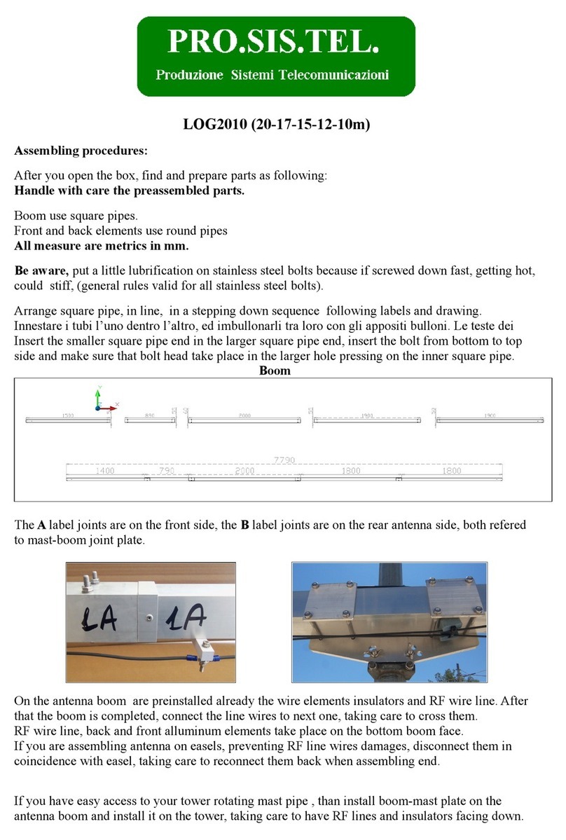
PRO.SIS.TEL. PST-1524TV User manual
PRO.SIS.TEL.
PRO.SIS.TEL. LOG2010 User manual

PRO.SIS.TEL.
PRO.SIS.TEL. PST-40VF Installation guide
PRO.SIS.TEL.
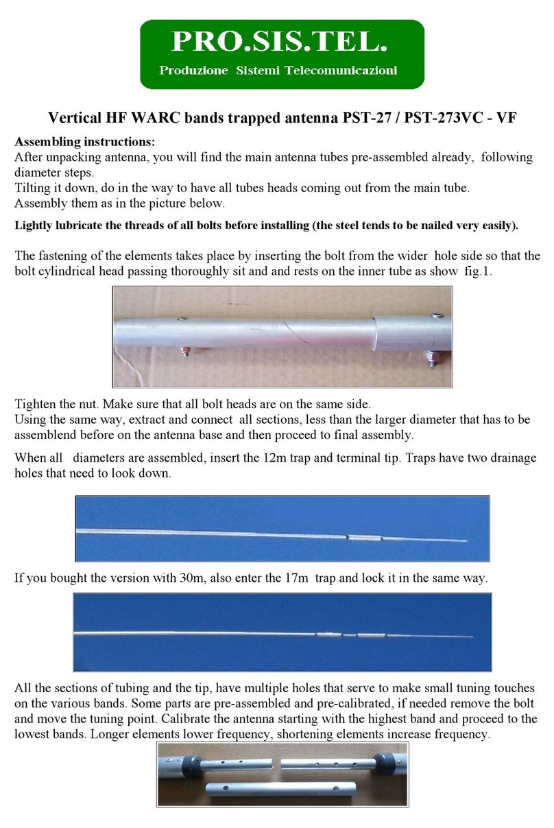
PRO.SIS.TEL. PST-27 Installation guide

PRO.SIS.TEL.
PRO.SIS.TEL. PST-32 Installation guide
Popular Antenna manuals by other brands
Electro-Metrics
Electro-Metrics SHL-30 instruction manual

CommScope
CommScope ValuLine VHLP1 Series installation instructions
RCA
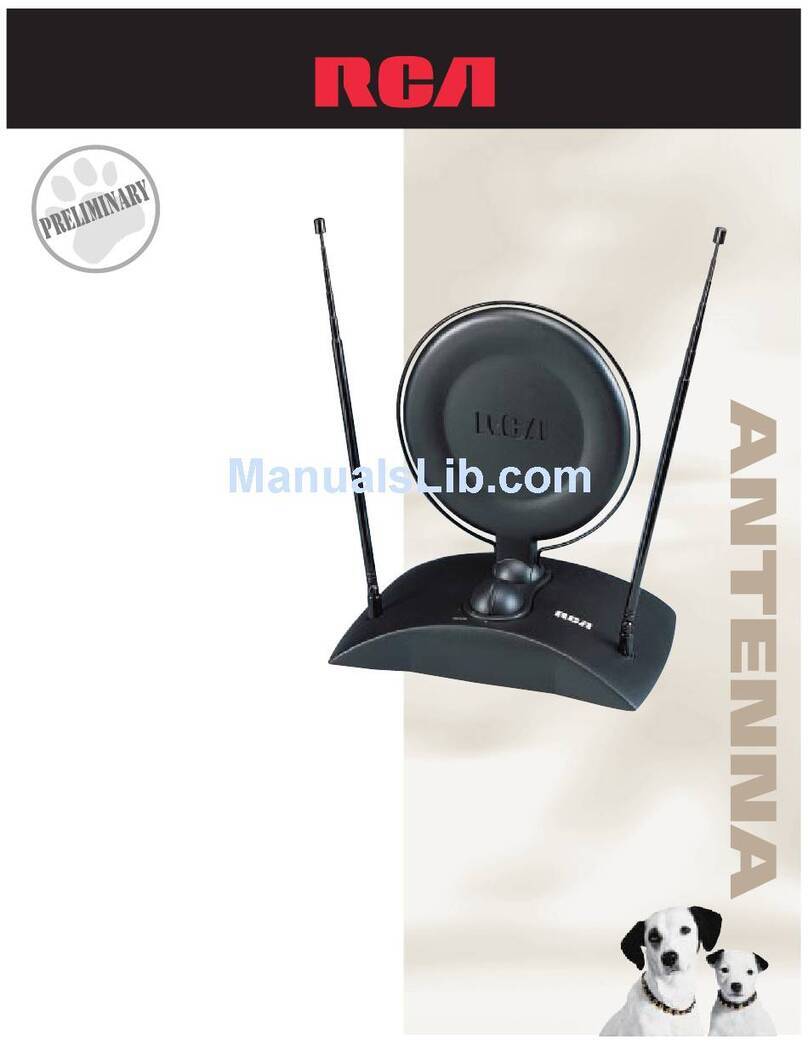
RCA ANT1200 Specifications
Philips
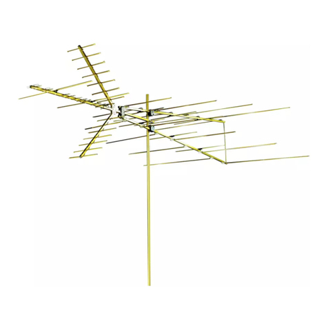
Philips MANT901 user manual

Sony
Sony SAN-18D1 installation manual
Directive Systems & Engineering
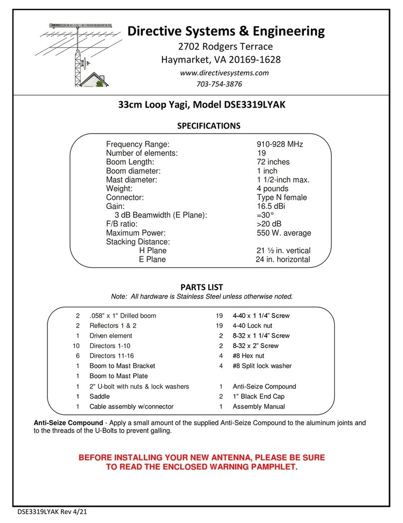
Directive Systems & Engineering DSE3319LYAK quick start guide
M2 Antenna Systems
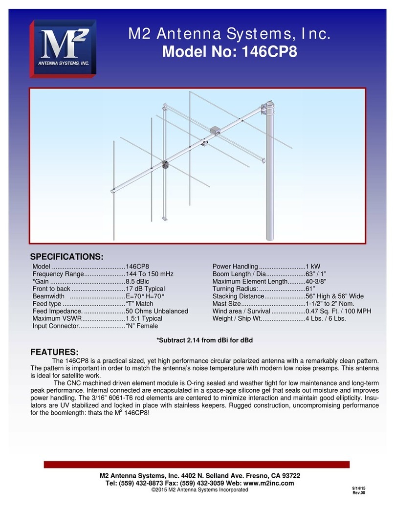
M2 Antenna Systems 146CP8 manual
CCOM
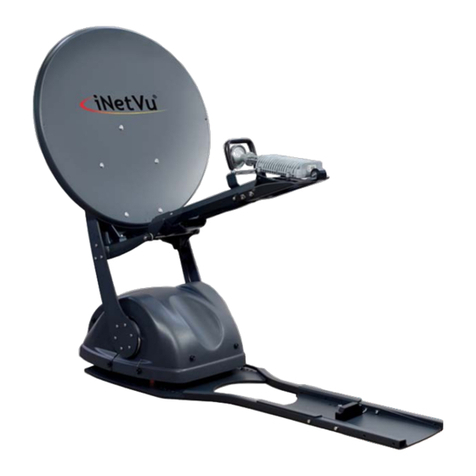
CCOM iNetVu 755 troubleshooting guide
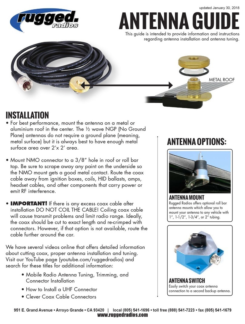
Rugged Computing
Rugged Computing WB-1/4W-HD Guide
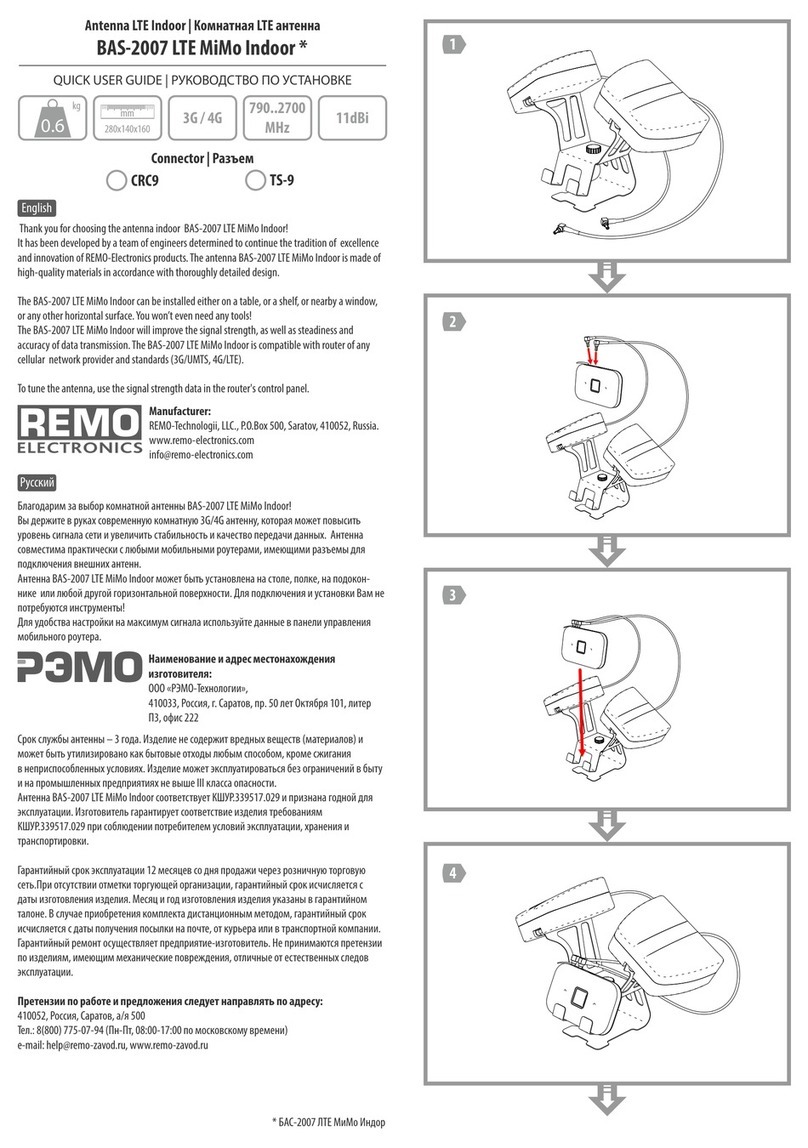
REMO Electronics
REMO Electronics BAS-2007 LTE MiMo Indoor Quick user guide
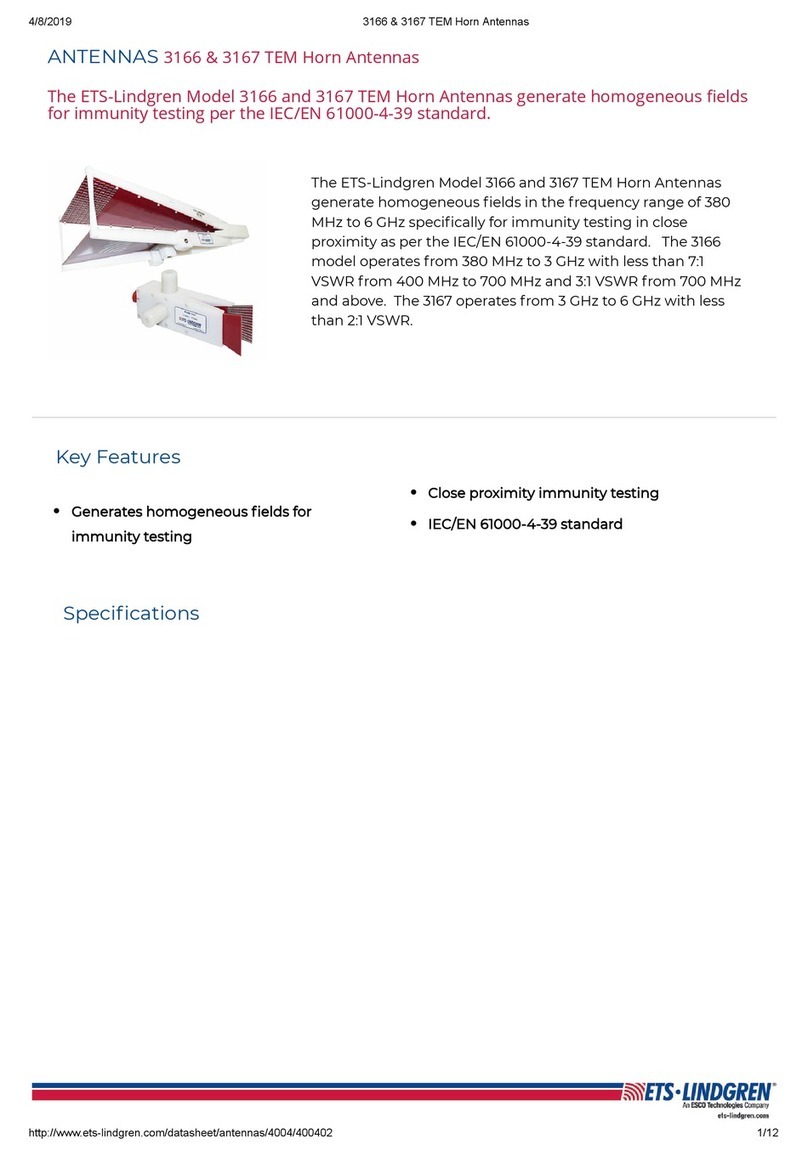
ESCO Technologies
ESCO Technologies ETS Lindgren 3166 manual
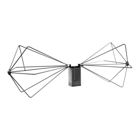
ETS-Lindgren
ETS-Lindgren 3109 user manual
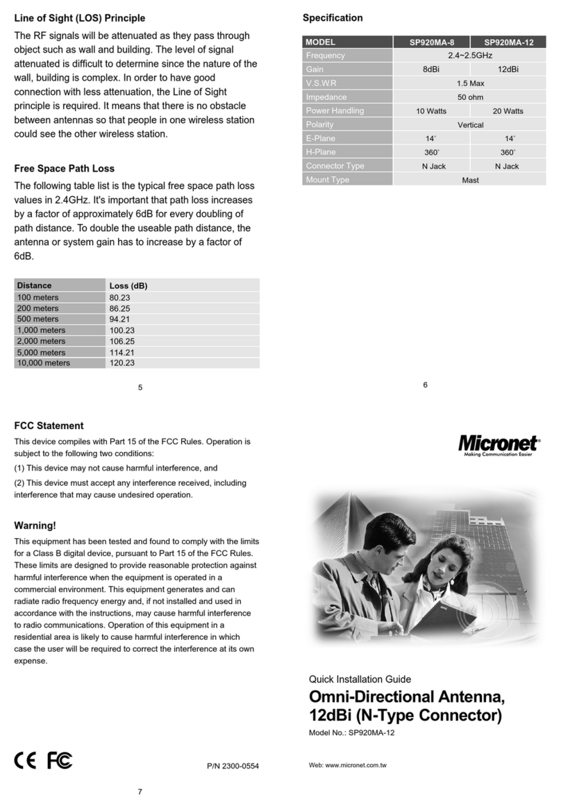
MicroNet
MicroNet SP920MA-8 Quick installation guide
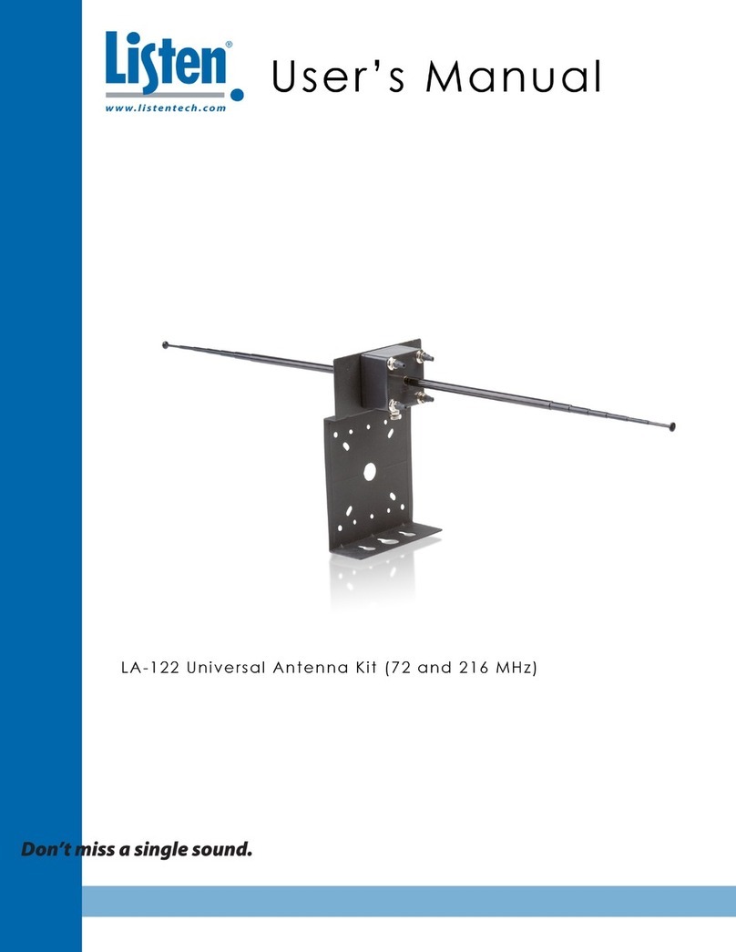
Listen Technologies
Listen Technologies UNIVERSAL ANTENNA KIT LA-122 user manual
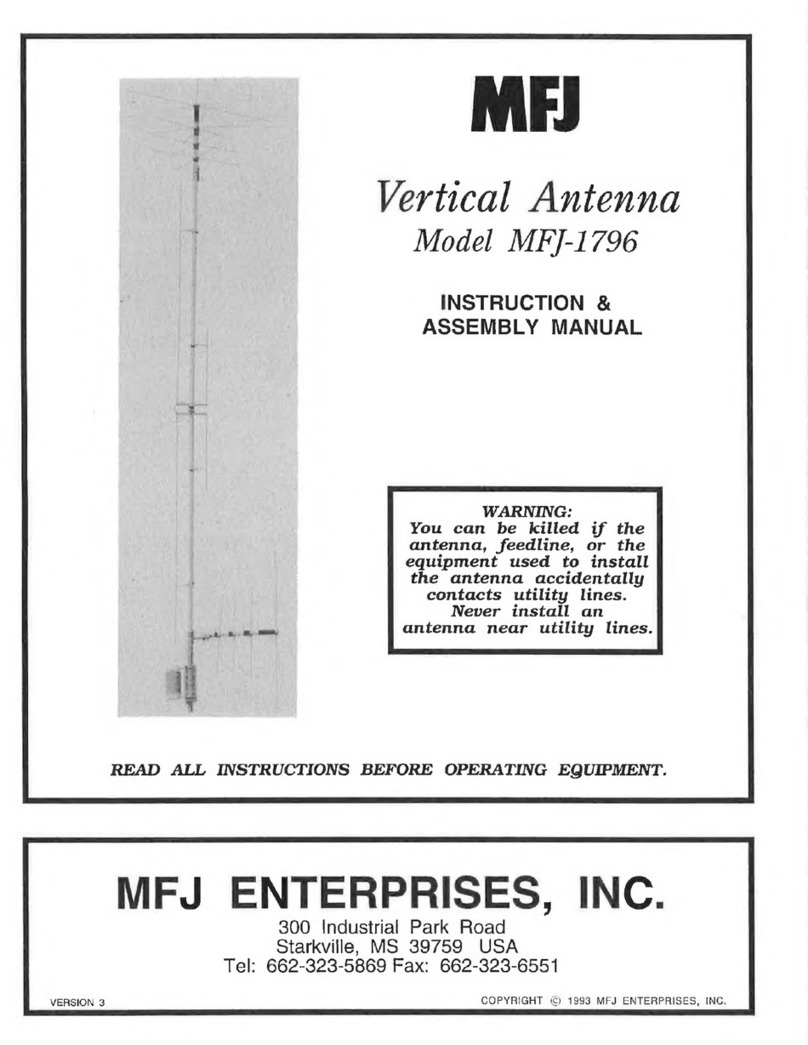
MFJ Enterprises
MFJ Enterprises MFJ-1796 Instruction & assembly manual
Sirius Satellite Radio
Sirius Satellite Radio SIR-WRR1 user guide
Hughes
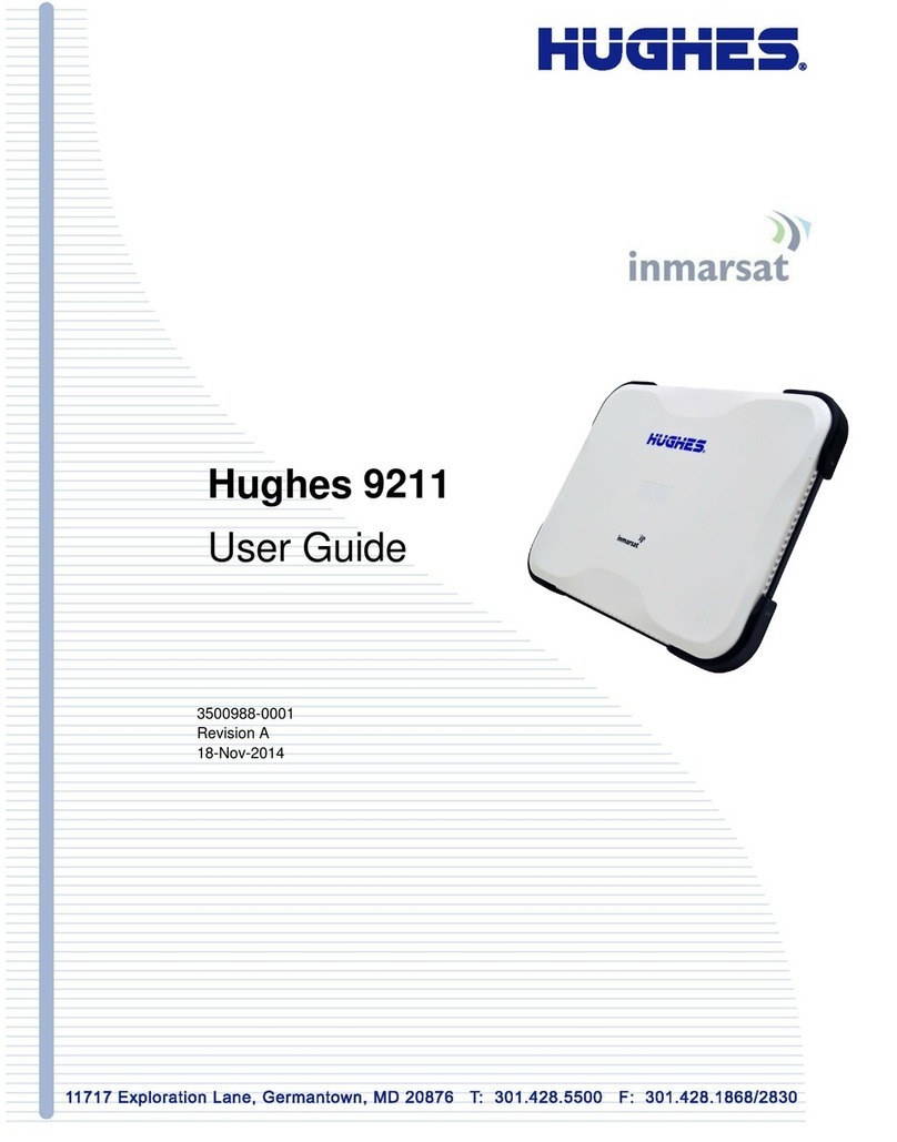
Hughes 9211 user guide

Renkforce
Renkforce 1399993 operating instructions


