Startco SE-330AU User manual

406 Jessop Avenue Saskatoon, Saskatchewan Canada S7N 2S5 Ph: (306) 373-5505 Fx: (306) 374-2245 www.startco.ca
SE-330AU MANUAL
NEUTRAL-EARTHING-RESISTOR MONITOR
May 16, 2007
Revision 0
NEUTRAL EARTHING RESISTOR
MONITOR
STARTCO
ENGINEERING LTD.
SE-330AU
E(A)FTRIPLEVEL
V TRIP LEVEL
(S5 20 K SR )
N
EFTRIPTIME( )
CALIBRATED
POWER
REL K1AY
DIAGNOSTIC
.10
.125 20
60
.12
.25
.14
.30
.16
.40
100
130
170
.18
.50
.20
.75 200
.25
.30
2.0
1200
.35
3.0
.40
4.0
.50
5.0 2000
1
Vx
N
1700
800
340
RESET
EARTH
FAULT
TRIP
1.0
RESISTOR
FAULT
TRIP
S
.75
1.5
1.8
2.4
3.0
4.5
6.0
12.0
18.0
24.0
30.0
EFCT
CS30
(S5 100 K SR )
5
W
W
Vx
N
Copyright 2007 Startco Engineering Ltd.
All rights reserved.
Publication: SE-330AU-M
Document: S95-C330-0A000
Printed in Canada.

Startco Engineering Ltd. Page i
SE-330AU Neutral-Earthing-Resistor Monitor Rev. 0
Pub. SE-330AU-M, May 16, 2007
TABLE OF CONTENTS
PAGE
Table of Contents .............................................................. i
List of Figures ................................................................... i
List of Tables..................................................................... i
1. General ................................................................... 1
1.1 Modern Resistance-Earthed Systems....................... 1
1.2 SE-330AU NER Monitoring ................................... 1
2. Operation................................................................ 1
2.1 Settings .................................................................... 1
2.1.1 EF Trip Time ................................................ 1
2.1.2 EF Trip Level................................................ 2
2.1.3 VNTrip Level ............................................... 2
2.1.4 Configuration Settings.................................. 3
2.1.4.1 Earth-Fault-Trip Latch (S3) ............. 3
2.1.4.2 Resistor-Fault-Trip Latch (S4)......... 3
2.1.4.3 Sensing-Resistor Selection (S5)....... 3
2.1.4.4 Frequency (S6)................................. 3
2.1.4.5 Upgrade Enable (S8)........................ 3
2.2 Calibration ............................................................... 3
2.3 CT Detection............................................................ 3
2.4 Trip Indication and Reset......................................... 3
2.5 Remote Operation.................................................... 4
2.6 Relay K1 LED ......................................................... 4
2.7 Unit Healthy Output ................................................ 4
2.8 Diagnostic LED ....................................................... 4
2.9 Analog Output ......................................................... 4
3. Installation.............................................................. 4
3.1 SE-330AU ............................................................... 4
3.2 Sensing Resistor ...................................................... 9
3.3 Earth-Fault CT....................................................... 14
3.4 Isolated Earth Connection...................................... 17
4. Communications .................................................. 18
4.1 Local Communication Port.................................... 18
4.1.1 Local Data Acquisition ............................... 18
4.1.2 Firmware Upgrade...................................... 18
4.2 Network Communications ..................................... 18
5. Troubleshooting ................................................... 19
6. Technical Specifications ...................................... 20
6.1 SE-330AU ............................................................. 20
6.2 Sensing Resistors................................................... 21
6.3 Current Sensors...................................................... 21
7. Ordering Information ......................................... 21
PAGE
8Warranty...............................................................22
9 Test Procedures ....................................................22
9.1 Resistor-Fault Tests................................................22
9.1.1 Calibration and Open Test..........................22
9.1.2 Voltage Test ...............................................22
9.2 Sensing-Resistor Test .............................................23
9.3 Analog-Output Test................................................23
9.4 Earth-Fault Performance Test.................................23
LIST OF FIGURES
FIGURE PAGE
1 Configuration Switches ............................................3
2 Analog-Output Connections.....................................4
3 SE-330AU Connection Diagram..............................6
4 SE-330AU Outline and Panel-Mounting Details......7
5 SE-330AU Outline and Surface-Mounting Details ..8
6 ER-600VC Sensing Resistor ....................................9
7 ER-5KV Sensing Resistor ......................................10
8 ER-15KV Sensing Resistor ....................................11
9 ER-25KV Sensing Resistor ....................................12
10 ER-35KV Sensing Resistor ....................................13
11 EFCT-1 Sensitive Earth-Fault Current
Sensor .................................................................14
12 SE-CS30-70 Sensitive Earth-Fault
Current Sensor....................................................15
13 EFCT-26 and SE-CS30-26 Sensitive Earth-
Fault Current Sensors .........................................16
14 RK-332 Remote Indication and Reset ....................17
15 Simplified Isolated-Earth Connection ....................17
16 Earth-Fault-Test Circuits ........................................23
LIST OF TABLES
TABLE PAGE
1 Typical Values for Tripping Systems.......................2
2 RS-232 DB-9 Terminals.........................................18
3 Earth-Fault-Test Record .........................................24
DISCLAIMER
Specifications are subject to change without notice. Startco
Engineering Ltd. is not liable for contingent or
consequential damages, or for expenses sustained as a result
of incorrect application, incorrect adjustment, or a
malfunction.

Startco Engineering Ltd. Page 1
SE-330AU Neutral-Earthing-Resistor Monitor Rev. 0
Pub. SE-330AU-M, May 16, 2007
1. GENERAL
1.1 MODERN RESISTANCE-EARTHED SYSTEMS
A high-resistance-earthed system uses a neutral-
earthing resistor (NER) with a low let-through current to
limit earth-fault current. High-resistance earthing is
gaining popularity because an earth-fault flash hazard
exists in low-resistance or solid-earthed systems and an
earth-fault can result in substantial point-of-fault damage.
High-resistance earthing eliminates these problems and
modern earth-fault protection operates reliably at these
levels. Furthermore, the probability of an arc-flash
incident is significantly reduced in a high-resistance NER
system.
NER selection depends on system charging current.
System charging current is the capacitive current that
flows to earth when a bolted earth fault occurs. This
current can be calculated or measured. For small systems,
the magnitude of charging current is typically ½ A per
1,000 kVA on low-voltage systems and 1 A per
1,000 kVA on medium-voltage systems.
Choose an NER with a let-through current larger than
the system charging current. Set the pick-up current of
earth-fault devices at or below 10% of the NER let-
through current for systems up to 1.1 KV and 20% of the
NER let through current for systems above 1.1 KV.
Use earth-fault devices with a definite-time characteristic
to achieve time coordination. Use the same pick-up current
for all earth-fault devices—this value must be larger than
the charging current of the largest feeder. Select an NER
with a let-through current between five and ten times the
pick-up current of the earth-fault devices.
Do not use an earthing transformer with a low-voltage
resistor:
•The combined cost of a transformer and a low-
voltage resistor is more than the cost of a resistor
rated for line-to-neutral voltage.
•A transformer saturated by an earth fault through a
rectifier can make earth-fault protection inoperative.
•Transformer inrush current up to twelve times rated
current can cause an earth-fault voltage larger than
expected.
•A parallel transformer winding makes it difficult to
monitor NER continuity.
•A transformer can provide the inductance necessary
to cause ferroresonance if the NER opens.
Following these guidelines will reduce the flash hazard,
reduce point-of-fault damage, achieve reliable earth-fault
protection, and ensure a stable system not subject to
ferroresonance.
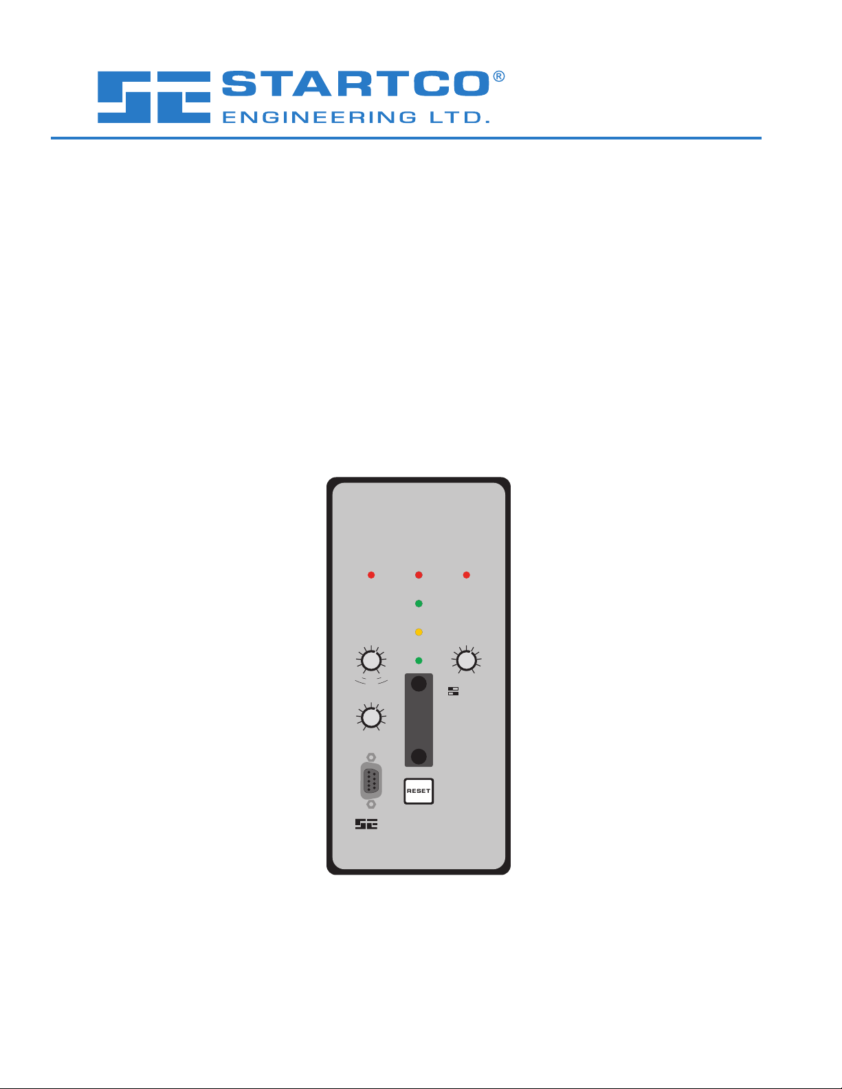
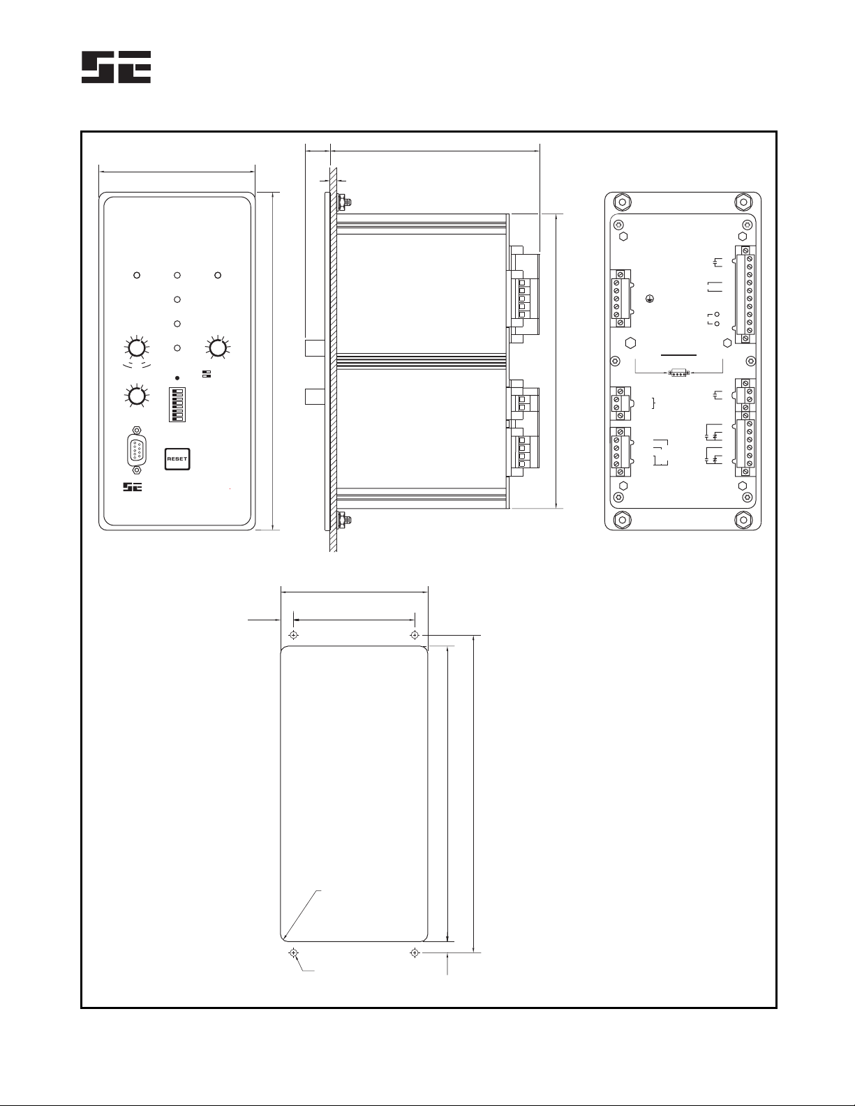
1.2 SE-330AU NER MONITORING
The SE-330AU is a microprocessor-based neutral-
earthing-resistor monitor that detects NER failures and
earth faults in resistance-earthed systems. The SE-330AU
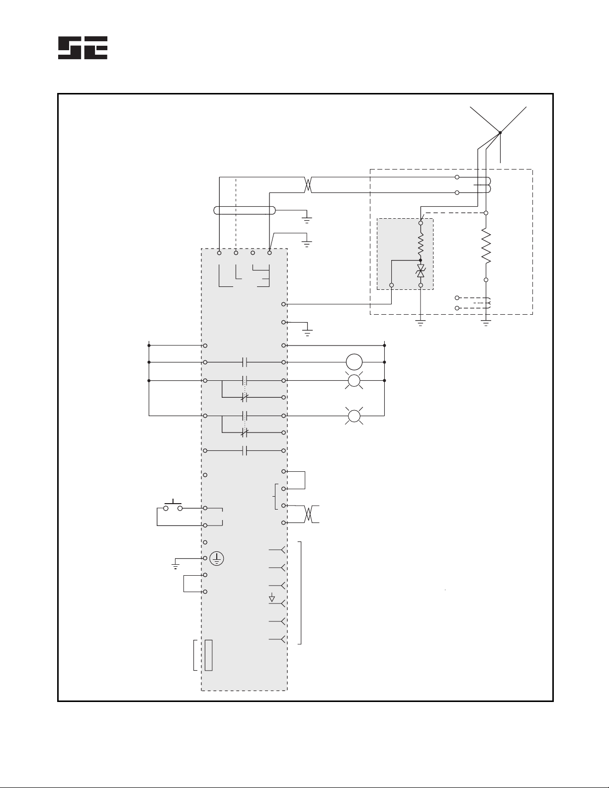
measures NER resistance, NER current, and transformer
or generator neutral-to-earth voltage. The components
required to monitor an NER are an SE-330AU, an ER-series
sensing resistor, and a current transformer (CT).
The SE-330AU continuously measures NER resistance
in an unfaulted system, and it will trip on resistor fault if
NER resistance varies from its calibrated value. When an
earth fault occurs, voltage is present on the neutral and
NER current will flow if the NER is healthy. The
SE-330AU will trip on earth fault if fault current exceeds
the EF TRIP LEVEL setting for an interval greater than
the EF TRIP TIME setting. However, if the NER fails
open during an earth fault, it is possible for fault
resistance to satisfy the NER resistance measurement. To
detect this double-fault condition, the SE-330AU
measures neutral voltage. If neutral voltage exceeds the
VNTRIP LEVEL setting, and if NER current is less than
5% of the CT rating, the SE-330AU will trip on resistor
fault. If the resistor-fault circuit is tripped and the neutral
voltage exceeds the VNTRIP LEVEL setting for an
interval greater than the EF TRIP TIME setting, the earth-
fault circuit will also trip.
Earth-fault current is sensed by a sensitive CT (EFCT-x
or SE-CS30-x). The trip level of the earth-fault circuit is
adjustable from 0.125 to 5 A for the EFCT-x and 0.75 to
30 A for the SE-CS30-x. Trip time is adjustable from 0.1
to 0.5 seconds. Open-CT detection is provided with a
fixed 2-second time delay.
The SE-330AU has four output relays. Relay K1 is the
trip relay. Relays K2 and K3 provide earth-fault and
resistor-fault indication. K4 is a solid-state relay that
provides UNIT HEALTHY indication. Relay K1
operates in the fail-safe mode for undervoltage
applications.
Additional features include LED trip indication, trip
memory, front-panel and remote reset, 4–20-mA analog
output, RS-232 local communications, and optional
network communications.
The SE-330AU is compatible with lockout earth-fault
protection devicesthe on line phase-to-earth resistance
added by coupling components must be above the
SE-330AU NER-failure-detection resistance.
2. OPERATION
2.1 SETTINGS
2.1.1 EF TRIP TIME
EF TRIP TIME (definite time) is adjustable from
0.1 to 0.5 seconds. Time-coordinated earth-fault protection
requires this setting to be longer than the trip times of
downstream earth-fault devices.

Startco Engineering Ltd. Page 2
SE-330AU Neutral-Earthing-Resistor Monitor Rev. 0
Pub. SE-330AU-M, May 16, 2007
2.1.2 EF TRIP LEVEL
The SE-330AU uses a Discrete-Fourier Transform
(DFT) algorithm to measure the fundamental component
of NER current.
Choose an NER let-through current and an earth-fault
trip level according to the guidelines in Section 1.1.
Typical values are shown in Table 1.
2.1.3 VNTRIP LEVEL
The SE-330AU uses a DFT algorithm to measure the
fundamental component of neutral voltage.
Calculate the voltage across the NER when NER
current is equal to the pick-up current of the earth-fault
circuit. Set the VNTRIP LEVEL at the next largest value.
The VNTRIP LEVEL range is 20 to 2,000 V with switch
S5 in the 20-kΩ(Vx1) position, and the range is 100 to
10,000 V with switch S5 in the 100-kΩ(Vx5) position.
See Fig. 1 and Section 2.1.4.3.
If neutral voltage is greater than the VNTRIP LEVEL
setting for 12 seconds and earth-fault current is less than
5% of the CT rating, the SE-330AU will trip on resistor
fault. If the resistor-fault circuit is tripped and the neutral
voltage exceeds the VNTRIP LEVEL setting for an
interval greater than the EF TRIP TIME setting, the earth-
fault circuit will also trip.
Typical values for NER systems are shown in Table 1.
NOTE:A resistor-fault trip is held off if the earth-fault
current is above 5% of the CT rating.
TABLE 1. TYPICAL VALUES FOR TRIPPING SYSTEMS
System Voltage (Volts) Neutral-Earthing
Resistor Earth-Fault Trip Level (Amperes)
Line to
Line
Line to
Neutral
Current
(Amperes)
Resistance
(Ohms)
EFCT-x
(5-A Rating)
SE-CS30-x
(30-A Rating)
VNTrip
Level
(Volts)
Sensing
Resistor S5
110 (3) 55 5 11 0.5 (1) 20 ER-600VC 20 kΩ
120 (3) 60 5 12 0.5 (1) 20 ER-600VC 20 kΩ
110 64 5 13 0.5 (1) 20 ER-600VC 20 kΩ
127 73 5 15 0.5 (1) 20 ER-600VC 20 kΩ
240 (3) 120 5 24 0.5 (1) 20 ER-600VC 20 kΩ
240 139 5 28 0.5 (1) 20 ER-600VC 20 kΩ
270 156 5 31 0.5 (1) 20 ER-600VC 20 kΩ
415 240 5 48 0.5 (1) 60 ER-600VC 20 kΩ
433 250 5 50 0.5 (1) 60 ER-600VC 20 kΩ
690 398 5 80 0.5 (1) 60 ER-600VC 20 kΩ
970 560 5 112 0.5 (1) 60 ER-5KV 20 kΩ
1,000 575 5 115 0.5 (1) 60 ER-5KV 20 kΩ
1,050 605 5 121 0.5 (1) 100 ER-5KV 20 kΩ
1,100 635 5 127 0.5 (1) 100 ER-5KV 20 kΩ
1,140 658 5 132 0.5 (1) 100 ER-5KV 20 kΩ
3,300 1,905 5 381 0.5 (1) 200 ER-5KV 20 kΩ
6,600 3,810 5 762 0.5 (1) 500 ER-15KV 100 kΩ
6,600 3,810 10 381 1.0 0.75 500 ER-15KV 100 kΩ
6,600 3,810 25 152 2.0 1.5 500 ER-15KV 100 kΩ
11,000 6,350 5 1,270 0.5 (1) 650 ER-15KV 100 kΩ
11,000 6,350 10 635 1.0 0.75 650 ER-15KV 100 kΩ
11,000 6,350 20 318 2.0 1.5 650 ER-15KV 100 kΩ
11,000 6,350 25 254 2.0 2.4 650 ER-15KV 100 kΩ
22,000 12,700 5 2,540 0.5 (1) 1,700 ER-25KV 100 kΩ
22,000 12,700 10 1,270 1.0 0.75 1,700 ER-25KV 100 kΩ
22,000 12,700 20 635 2.0 1.5 1,700 ER-25KV 100 kΩ
22,000 12,700 25 508 2.0 2.4 1,700 ER-25KV 100 kΩ
22,000 12,700 50 254 (2) 24 8,500 ER-25KV 100 kΩ
33,000 19,050 50 380 (2) 24 10,000 ER-35KV 100 kΩ
(1) Minimum setting is 0.75 A. Use EFCT-x for AS/NZS 2081 compliance.
(2) Maximum setting is 5 A. AS/NZS 2081 allows 25 A.
(3) Single phase, centre tap.

Startco Engineering Ltd. Page 3
SE-330AU Neutral-Earthing-Resistor Monitor Rev. 0
Pub. SE-330AU-M, May 16, 2007
2.1.4 CONFIGURATION SETTINGS
Eight configuration switches (S1 to S8) and a
calibration push button are located behind the access
cover on the front panel. See Fig. 1. Switches S1, S2 and
S7 are not used.
LATCHING RF TRIP
LATCHING E TRIPF
20 kW
50 Hz
NOT USED
NOT USED
NOT USED
RUN
NON-LATCHING RF TRIP
NON-LATCHING EF TRIP
100 kW
60 Hz
UPGRADE
S1
S2
S3
S4
S5
S6
S7
S8
CALIBRATION PUSH BUTTON
NOTE: DEFAULT SETTINGS SHOWN.
CAL
FIGURE 1. Configuration Switches.
2.1.4.1 EARTH-FAULT-TRIP LATCH (S3)
Set switch S3 to select latching or non-latching earth-
fault-circuit operation. See Section 2.4.
2.1.4.2 RESISTOR-FAULT-TRIP LATCH (S4)
Set switch S4 to select latching or non-latching resistor-
fault-circuit operation. See Section 2.4
2.1.4.3 SENSING-RESISTOR SELECTION (S5)
Set switch S5 to the resistance of the sensing resistor. For
the ER-600VC and ER-5KV, select 20 kΩ. For the
ER-15KV, ER-25KV, and ER-35KV, select 100 kΩ.
Switch S5 sets the VNTRIP LEVEL range. See
Section 2.1.3.
2.1.4.4 FREQUENCY (S6)
Set switch S6 to 50 or 60 Hz to tune the digital filter to
the line frequency of the monitored system.
2.1.4.5 UPGRADE ENABLE (S8)
Set switch S8 to RUN for normal operation or to
UPGRADE to enable firmware upgrades. Changes in
switch S8 settings are recognized only when supply
voltage is cycled. Protection is disabled after supply
voltage is cycled with S8 in the UPGRADE position. See
Section 4.1.2.
2.2 CALIBRATION
The SE-330AU measures the resistance change of the
NER relative to the NER-resistance value determined at
the time of calibration. Calibrate the SE-330AU on new
installations, if the NER is changed, or if the sensing
resistor is changed.
The CALIBRATION push button is located behind the
access cover on the front panel, and it is recessed to
prevent inadvertent activation.
NOTE:Calibration must be performed with the
SE-330AU connected to the sensing resistor and NER of
the installed system.
NOTE:Where used, coupling components for lockout
earth-fault protection devices must be disconnected from
the supply during calibration.
To calibrate, press and hold the CALIBRATION push
button until the green CALIBRATED LED turns off and
returns to on (if the LED is already off, press and hold
until the LED turns on). Calibration takes approximately
two seconds. If calibration is not successful, a resistor-
fault trip occurs, the RESISTOR FAULT TRIP LED will
be on, the CALIBRATED LED will be off, and the
DIAGNOSTIC LED will flash the calibration-error code.
See Section 2.8.
If latching resistor fault (switch S4) is selected, the
calibration-error code flashes until RESET is pressed
even if the CALIBRATED LED is on.
The calibration value is stored in non-volatile memory.
2.3 CT DETECTION
The SE-330AU monitors the continuity of the CT circuit.
When an open CT circuit is detected for 2 seconds, the
SE-330AU will trip on earth fault and the diagnostic LED
will flash the CT-Detection-Error code. See Section 2.8.
The CT-Detection-Error code remains until CT-circuit
continuity is detected and RESET is pressed. If supply
voltage is cycled, earth-fault trip indication is not reset but
the CT-Detection-Error indication is reset. CT-Detection-
Error indication will resume after 2 seconds if CT-circuit
continuity is not detected.
2.4 TRIP INDICATION AND RESET
Red LED's and indication relays indicate earth-fault
and resistor-fault trips—indication relays K2 and K3 are
energized on trip. When a trip occurs with latching
operation selected, the SE-330AU remains tripped until
reset. See Sections 2.1.4.1 and 2.1.4.2. Terminals 15 and
16 are provided for remote reset as shown in Fig. 3. The
reset circuit responds only to a momentary closure so that
a jammed or shorted switch does not prevent a trip. The
front-panel RESET switch is inoperative when terminal
15 is connected to terminal 16. If non-latching operation
is selected, trips and corresponding indication
automatically reset when the fault clears. Resistor-fault-
trip reset can take up to one second.
The red DIAGNOSTIC LED annunciates latched
calibration-error and remote trips. See Section 2.8.
When supply voltage is applied, the SE-330AU returns
to its state prior to loss of supply voltage.

Startco Engineering Ltd. Page 4
SE-330AU Neutral-Earthing-Resistor Monitor Rev. 0
Pub. SE-330AU-M, May 16, 2007
2.5 REMOTE OPERATION
Relays K2 and K3 can be used for remote indication,
and terminals 15 and 16 are provided for remote reset.
RK-332 Remote Indication and Reset components are
shown in Fig. 14. Connect them as shown in Fig. 3.
RK-332 components are not polarity sensitive.
Network-enabled SE-330AU’s can be remotely tripped
and reset by the network master. The red DIAGNOSTIC
LED indicates a network-initiated trip. See Section 2.8.
Refer to the appropriate SE-330 communications manual.
2.6 RELAY K1 LED
The yellow RELAY K1 LED follows the state of relay
K1 and is on when K1 is energized (contact closed).
2.7 UNIT HEALTHY OUTPUT
UNIT HEALTHY relay K4 is energized when the
processor is operating. It can be ordered with N.O. or
N.C. contacts. See Section 7.
NOTE:The K4 output changes state momentarily during
a processor reset.
NOTE:K4-contact rating is 100 mA maximum.
2.8 DIAGNOSTIC LED
The DIAGNOSTIC LED is used to annunciate trips
without individual LED indication. The number of short
LED pulses between two long pulses indicates the cause
of the trip.
Calibration-Error Trip (1 short):
The calibration resistance of the NER is outside the
calibration range. See Section 6.1.
Remote Trip (2 short):
The SE-330AU has been tripped by a remote-trip
command from the communications interface.
CT Detection Error Trip (3 short)
An open CT circuit has been detected
A/D-Converter-Error Trip (4 short):
An A/D-converter error has occurred.
Software-Interrupt Trip (5 short):
CPU reset was caused by a software interrupt.
Illegal-Opcode Trip (6 short):
CPU reset was caused by an illegal Opcode.
Watchdog Trip (7 short):
CPU reset was caused by the watchdog.
Clock-Failure Trip (8 short):
CPU reset was caused by an internal clock failure.
Trap-Code Trip (9 short):
This code is displayed if the supply is cycled after one
of the previous four errors occurred.
EEPROM-Error Trip (10 short):
An EEPROM error has been detected.
Resistor-fault trips occur with all of the above trips
except the CT Detection Error. Earth-fault trips occur
with all of the above trips except the calibration-error trip
and the A/D-converter-error trip.
See Troubleshooting Section 5.
2.9 ANALOG OUTPUT
An isolated 4–20-mA output indicates NER current
with full-scale output corresponding to the CT rating. An
internal 24-Vdc supply allows the analog output to be
connected as a self-powered output. Power from an
external supply is required for loop-powered operation.
See Fig. 2.
FIGURE 2. Analog-Output Connections.
3. INSTALLATION
3.1 SE-330AU
Outline and panel-cutout dimensions for the SE-330AU
are shown in Fig. 4. To panel mount the SE-330AU,
insert it through the panel cutout and secure it with four
8-32 locknuts and flat washers (included).
All connections to the SE-330AU are made with
plug-in, wire-clamping terminal blocks. Each plug-in
terminal block can be secured to the monitor by two
captive screws for reliable connections.

Startco Engineering Ltd. Page 5
SE-330AU Neutral-Earthing-Resistor Monitor Rev. 0
Pub. SE-330AU-M, May 16, 2007
Outline dimensions and mounting details for surface
mounting the SE-330AU are shown in Fig. 5. Fasten the
optional SE-330-SMA Surface-Mount Adapter to the
mounting surface and make connections to the adapter
terminal blocks. Follow Fig. 5 instructions to mount or
remove the SE-330AU.
Connect terminal 7 (G) to earth and connect terminal
6 (R) to the sensing-resistor R terminal.
Use terminal 1 (L1) as the line terminal on ac systems,
or the positive terminal on dc systems. Use terminal 2
(L2/N) as the neutral terminal on ac systems or the
negative terminal on dc systems. Connect terminal 3 ( )
to earth. Connect terminal 4 (SPG) to terminal 5 (SPGA).
Remove the terminal-4-to-5 connection for dielectric-
strength testing.
NOTE: When the terminal-4-to-5 connection is removed,
protective circuits inside the SE-330AU are disconnected
to allow dielectric strength testing of a control panel
without having to disconnect wiring to the SE-330AU.
Ensure that the terminal-4-to-5 connection is replaced
after testing.

Startco Engineering Ltd. Page 6
SE-330AU Neutral-Earthing-Resistor Monitor Rev. 0
Pub. SE-330AU-M, May 16, 2007
NOTES:
USE SEPARATE LUG TO CONNECT SENSING-
RESISTOR TERMINAL N TO NEUTRAL.
LOCATE THESE COMPONENTS NEAR
TRANSFORMER OR GENERATOR.
ALTERNATE SENSING-RESISTOR
TERMINAL-N CONNECTION.
VOLTAGE BETWEEN SENSING-RESISTOR
TERMINALS R AND G IS LIMITED TO 100 V BY
INTERNAL CLAMP.
SEE SECTION 3.4 FOR ISOLATED-EARTH
CONNECTION.
ALTERNATE CT LOCATION.
RELAY CONTACTS SHOWN WITH SE-330AU
DE-ENERGIZED.
LOOP-POWERED CONNECTION USES
TERMINALS 19 AND 20 ONLY.
RS232 PIN 4 (DTR), PIN 7 (RTS), AND
PIN 9 (RI) NOT CONNECTED.
REFER TO APPROPRIATE SE-330
COMMUNICATIONS INTERFACE MANUAL.
2.
1.
3.
4.
6.
5.
7.
8.
9.
10.
11.
EFCT-x
OR
SE-CS30-x
NER
SENSING
RESISTOR
N
NEUTRAL
NOTE 1
NOTE 2
NOTE 3
NOTE 4
NOTE 6
NOTE 5
RG
NOTE 7
NOTE 9
NOTE 8
L (CONTROL)
7
23
24
25
27
28
2
1
29
26
22
L1 L2/N
13
12
14 NC
NC
UNIT HEALTHY
EF EARTH
FAULT
RF RESISTOR
FAULT
N (CONTROL)
C
K1
K4
K3
K2
G
SE-330AU
5
4
3
SPGA
SPG
+24V
ANALOG OUTPUT
0V
DCD
DSR
CTS
RxD
TxD
RESET
18
19
20
21
1
6
8
2
3
5
REMOTE
RESET
17
16
15
+
–
SELF POWERED
4-20 mA
OUTPUT
EF CS C
CS30
EFCT
C
6
R
891011
RS232 COM
NOTE 10
OPTIONAL
NETWORK COM
NOTE 11
TRANSFORMER
OR GENERATOR
OPTIONAL N.C. AVAILABLE.
DASHED LINE IS SE-CS30-x CONNECTION.
12.
NOTE 12
FIGURE 3. SE-330AU Connection Diagram.

Startco Engineering Ltd. Page 7
SE-330AU Neutral-Earthing-Resistor Monitor Rev. 0
Pub. SE-330AU-M, May 16, 2007
98.3
132.0
92.7
76.28.2
16.0
212.6
185.4
200.0
186.0
7.0
(3.87)
(5.20)
(3.65)
(3.00)(0.32)
(0.63)
(8.37)
(7.30)
(7.87)
(7.32)
(0.28)
FRONT VIEW
NOTE 2
SIDE VIEW
PANEL-MOUNT CUTOUT
REAR VIEW
PANEL THICKNESS
1.6 (0.06) TO 4.8 (0.19)
NOTES:
1. DIMENSIONS IN MILLIMETRES (INCHES).
2. SE-330AU SHOWN WITHOUT SWITCH
ACCESS COVER.
4.4 (0.173) DIA
4 LOCATIONS
R=4.8 (0.19)
MAXIMUM
1
4
2
3
5
-
-
-
-
-
-
-
-
-
-
-
-
-
-
-
-
L1
L2/N
SPG
SPGA
RSENSING
RESISTOR
G
EF
CS
C
C
S
3
0
E
F
C
T
C
6
7
10
8
11
9
12
13
14
15
16
17
18
19
20
21
UNIT
HEALTHY K4
NC
24V
0V
RESET
ANALOG OUTPUT
27
28
29
22
23
24
25
26
K3
K2
EARTH
FAULT
RESISTOR
FAULT
K1
ATTENTION
DISENGAGE CAPTIVE RETAINING
SCREWS BEFORE REMOVING
PLUG-IN TERMINAL BLOCKS
+
+
-
NEUTRAL EARTHING RESISTOR
MONITOR
STARTCO
ENGINEERING LTD.
SE-330AU
CALIBRATED
POWER
REL K1AY
DIAGNOSTIC
RESET
CAL
4
5
6
7
8
3
2
1
EARTH
FAULT
TRIP
RESISTOR
FAULT
TRIP
V TRIP LEVEL
(S5 20 K SR )
N
20
60
100
130
170
200
1200
2000
1
Vx
N
1700
800
340
(S5 100 K SR )
5
W
W
Vx
N
E(A)FTRIPLEVEL
.125
.25
.30
.40
.50
.75
2.0
3.0
4.0
5.0
1.0
.75
1.5
1.8
2.4
3.0
4.5
6.0
12.0
18.0
24.0
30.0
EFCT
CS30
-
NC
EFTRIPTIME( )
.10
.12
.14
.16
.18 .20 .25
.30
.35
.40
.50
S
FIGURE 4. SE-330AU Outline and Panel-Mounting Details.

Startco Engineering Ltd. Page 8
SE-330AU Neutral-Earthing-Resistor Monitor Rev. 0
Pub. SE-330AU-M, May 16, 2007
(1.00)
25.4
(2.50)
63.5
215.9 5.0
(8.50) (0.20)
MOUNTING DETAIL
BEZEL OUTLINE
ADAPTER PANEL OUTLINE
(NOTE 2)
NOTES:
MONITOR INSTALLATION
MONITOR REMOVAL
1. DIMENSIONS IN MILLIMETRES (INCHES).
2. MOUNTING SCREWS: M4 OR 8-32 PANHEAD.
LOOSEN RETAINER SCREWS, MOVE RETAINERS
OUTWARD, AND TIGHTEN RETAINER SCREWS.
MATE MONITOR WITH ADAPTER PLUG-IN TERMINALS.
LOOSEN RETAINER SCREWS TO LET RETAINERS
SNAP OVER MONITOR BACKPLATE.
LOOSEN RETAINER SCREWS, SLIDE RETAINERS AWAY
FROM MONITOR BODY, AND TIGHTEN RETAINER SCREWS.
PULL MONITOR FORWARD.
1.
2.
3.
1.
2.
ENSURE THAT RETAINERS ARE AGAINST MONITOR
BODY AND TIGHTEN RETAINER SCREWS.
98.3 138.0
114.3
8.0
(3.87) (5.43)
(4.50)
(0.31)
212.6
225.4
6.4
(8.37)
(8.87)
(0.25)
FRONT VIEW SIDE VIEW
FRONT VIEW
SE-330-SMA
RETAINER SCREW
RETAINER
NEUTRAL EARTHING RESISTOR
MONITOR
STARTCO
ENGINEERING LTD.
SE-330AU
CALIBRATED
POWER
REL K1AY
DIAGNOSTIC
RESET
1 1
4 4
2 2
3 3
5 5
-
-
-
-
-
-
-
-
-
-
-
-
L1
L2/N
SPG
SPGA
R
SENSING
RESISTOR G
6 6
7 7
10
8
11
9
12
13
14
15
16
17
18
19
20
21
UNIT
HEALTHY
K4
NC
24V
0V
RESET
PULSE ENABLE
SE-330 ONLY
ANALOG OUTPUT
27
28
29
22
23
24
25
26
K3
K2
GROUND
FAULT
/EARTH
RESISTOR
FAULT
K1
+
+
-
EARTH
FAULT
TRIP
RESISTOR
FAULT
TRIP
E(A)FTRIPLEVEL
V TRIP LEVEL
(S5 20 K SR )
N
EFTRIPTIME( )
.10
.125 20
60
.12
.25
.14
.30
.16
.40
100
130
170
.18
.50
.20
.75 200
.25
.30
2.0
1200
.35
3.0
.40
4.0
.50
5.0 2000
1
Vx
N
1700
800
340
1.0
S
.75
1.5
1.8
2.4
3.0
4.5
6.0
12.0
18.0
24.0
30.0
EFCT
CS30
(S5 100 K SR )
5
W
W
Vx
N
-
-
-
-
S
1
5
C
10
8
11
9
SE-330
SE-330HV
EF
CS
C
C
SE-330AU
FIGURE 5. SE-330AU Outline and Surface-Mounting Details.

Startco Engineering Ltd. Page 9
SE-330AU Neutral-Earthing-Resistor Monitor Rev. 0
Pub. SE-330AU-M, May 16, 2007
3.2 SENSING RESISTOR
Outline and mounting details for ER-600VC, ER-5KV,
ER-15KV, ER-25KV, and ER-35KV sensing resistors are
shown in Figs. 6, 7, 8, 9, and 10. Locate the NER and the
sensing resistor near the transformer or generator. Connect
terminal G to earth. Pass the sensing-resistor-to-neutral
conductor and the NER-to-neutral conductor through the
earth-fault-CT window as shown in Fig. 3. Separately
connect sensing-resistor terminal N and the NER to the
neutral to include neutral connections in the monitored loop.
If an earth fault in the sensing-resistor conductor is unlikely,
a minimal loss of protection will result if it does not pass
through the earth-fault-CT window. See Note 3 in Fig. 3.
CAUTION:Voltage at terminal N rises to line-to-neutral
voltage when an earth fault occurs. The same clearances are
required for sensing resistors as for NER’s.
NOTE:The neutral-to-sensing-resistor-terminal-N connection
is not a neutral conductor. Since current through this
conductor is always less than 250 mA, a 1.5 mm2
conductor insulated to the system voltage is more than
sufficient.
NOTE: For outdoor installations, sensing resistors must be
in an IP14 enclosure.
MOUNTING DETAIL
105.0
8.0
89.0
8.0
40.0
19.0 10.510.5
(4.13)
(0.31)
(3.50)
(0.31)
(1.57)
(0.75) (0.41)(0.41)
NOTE 3
SIDE
41.5
22.2
(1.63)
(0.87)
FRONT
NOTES:
1.
2.
3.
4.
5.
DIMENSIONS IN MILLIMETRES (INCHES).
TERMINAL-BLOCK SCREWS: 6-32 x 0.25.
MOUNTING SCREWS: M4 OR 8-32.
ON REVISION 2 UNITS ENCLOSURE IS ELECTRICALLY CONNECTED
TO TERMINAL G THROUGH JUMPER FROM TERMINAL G TO SCREW.
THIS CONNECTION MAY BE REMOVED FOR DIELECTRIC STRENGTH
TESTING. ENSURE THAT THE JUMPER IS INSTALLED AFTER TESTING.
ON REVISION 1 UNITS, SCREW IS NOT PRESENT AND ENCLOSURE
IS ELECTRICALLY CONNECTED TO TERMINAL G.
4.5 (0.18) DIA
C'BORE 10.0 (0.39) DIA
3.2 (0.13) DEEP
40.0
105.0
(1.57)
(4.13)
RATINGS:
MAXIMUM VOLTAGE . 600 Vac
MAXIMUM CURRENT . 30 mA
RESISTANCE .......20k
THERMAL:
420Vac ..........CONTINUOUS
600Vac ..........6MINUTES ON,
60 MINUTES OFF
W
N
R
G
ER-600VC
SENSING RESISTOR
20 K
600 VAC MAX
W
STARTCO
MADE IN SASKATOON, CANADA
ENGINEERING LTD.
FIGURE 6. ER-600VC Sensing Resistor.

Startco Engineering Ltd. Page 10
SE-330AU Neutral-Earthing-Resistor Monitor Rev. 0
Pub. SE-330AU-M, May 16, 2007
355.6
254.0
127.0
457.0
50.7 (14.00)
(10.00)
(5.00)
(18.00)
(2.00)
MINIMUM DISTANCE
TO ADJACENT OBJECTS
MOUNTING DETAIL
NOTE 3
NOTES:
1.
2.
3.
4.
DIMENSIONS IN MILLIMETRES (INCHES).
TERMINAL-BLOCK SCREWS: 6-32 x 0.25.
MOUNTING SCREWS: M6 OR 0.25-20.
THIS DEVICE CAN DISSIPATE
300 WATTS. TO MINIMIZE SURFACE
TEMPERATURES FOR SYSTEMS
ALLOWED TO OPERATE
CONTINUOUSLY WITH A GROUND
FAULT, MOUNT VERTICALLY WITH
R & G TERMINALS DOWN.
ON REVISION 2 UNITS BASE IS
ELECTRICALLY CONNECTED TO
TERMINAL G THROUGH JUMPER
FROM TERMINAL G TO SCREW.
THIS CONNECTION MAY BE
REMOVED FOR DIELECTRIC
STRENGTH TESTING. ENSURE
THAT THE JUMPER IS INSTALLED
AFTER TESTING.
ON REV 0 & 1 UNITS SCREW IS NOT
PRESENT AND BASE IS ELECTRICALLY
CONNECTED TO TERMINAL G.
316.0
GR
188.0
(12.44)
(7.40)
FRONT VIEWSIDE VIEW
0.25-20 UNC STUD
VOLTAGE ON THIS SURFACE RISES
TO LINE-TO-NEUTRAL VOLTAGE
WHEN A GROUND FAULT OCCURS
N
CAUTION
HIGH VOLTAGE
STARTCO
ENGINEERING LTD.
MADE IN SASKATOON, CANADA
ER-5KV
SENSING RESISTOR
20 K
2500 VAC MAX
W
381.0
21.0
12.0
105.0
7.9
52.5
(15.00)
(0.83)
(0.47)
(4.13)
(0.31)
(2.07)
NEUTRAL CONNECTION
ALTERNATE NEUTRAL CONNECTION
TOP VIEW
0.25-20 UNC
THREADED
INSERT
10-32 THREADED
INSERT
RATINGS:
MAXIMUM VOLTAGE . 2,500 Vac
MAXIMUM CURRENT . 125 mA
RESISTANCE .......20k
THERMAL ..........CONTINUOUS
W
5.
MINIMUM CLEARANCE FROM BASE
254.0 (10.00)
NOTES 5 & 6
NOTE 2
REVISION 1, 030507
6.
FIGURE 7. ER-5KV Sensing Resistor.

Startco Engineering Ltd. Page 11
SE-330AU Neutral-Earthing-Resistor Monitor Rev. 0
Pub. SE-330AU-M, May 16, 2007
N
STARTCO
ENGINEERING LTD.
MADE IN SASKATOON, CANADA
VOLTAGE AT TERMINAL N RISES
TO LINE-TO-NEUTRAL VOLTAGE
WHEN A GROUND FAULT OCCURS
CAUTION
HIGH VOLTAGE
ER-15KV
SENSING RESISTOR
100 K
8400 VAC MAX
1MINUTEMAX
W
422.0
(16.61)
144.0
215.0
90.0
280.0
100.0
90.0
(5.67)
(8.46)
(3.53)
(11.00)
(3.94)
(3.53)
FRONT
MOUNTING DETAIL
SIDE
NOTES:
TOP
444.0
(17.50)
(14.37)(1.56) (1.56)
365.039.5 39.5
MINIMUM DISTANCE
TO ADJACENT OBJECTS
NOTE 3
1. DIMENSIONS IN MILLIMETRES
(INCHES).
2. TERMINAL-BLOCK SCREWS:
6-32 x 0.25.
3. MOUNTING SCREWS:
M6 OR 0.25-20.
4. USE LIQUID-TIGHT GLAND FOR
TERMINAL-BLOCK-ENCLOSURE
CABLE ENTRY.
132.0
(5.20)
RATINGS:
MAXIMUM VOLTAGE . . 8,400 Vac
MAXIMUM CURRENT . 84 mA
RESISTANCE .......100k
THERMAL ..........1MINUTE ON,
120 MINUTES
OFF
W
R
G
MINIMUM CLEARANCE FROM BASE
305.0 (12.00)
0.25-20 BINDING HEAD
20.5
(0.81)
NOTE 2
FIGURE 8. ER-15KV Sensing Resistor.

Startco Engineering Ltd. Page 12
SE-330AU Neutral-Earthing-Resistor Monitor Rev. 0
Pub. SE-330AU-M, May 16, 2007
800
60 340.0340.0
534
217 100.0
(31.5)
(2.4) (13.38)(13.38)
(21.0)
(8.5) (3.94)
MOUNTING DETAIL
NOTES:
1. DIMENSIONS IN
MILLIMETRES (INCHES).
2. TERMINAL-BLOCK SCREWS:
6-32 x 0.25.
3. MOUNTING SCREWS:
M6 OR 0.25-20.
4. USE LIQUID-TIGHT GLAND
FOR TERMINAL-BLOCK-
ENCLOSURE CABLE ENTRY.
NOTE 3
MINIMUM DISTANCE
TO ADJACENT OBJECTS
320
(12.6)
FRONT SIDE
N
STARTCO
ENGINEERING LTD.
MADE IN SASKATOON, CANADA
VOLTAGE AT TERMINAL N RISES
TO LINE-TO-NEUTRAL VOLTAGE
WHEN A GROUND FAULT OCCURS
CAUTION
HIGH VOLTAGE
ER-25KV
SENSING RESISTOR
100 K
14,400 VAC MAX
1MINUTEMAX
W
780
(5.67)
20.5
(30.7)
(0.81)
TOP
RATINGS:
MAXIMUM VOLTAGE . 14,400 Vac
MAXIMUM CURRENT . 144 mA
RESISTANCE .......100k
THERMAL ..........1MINUTE ON,
120 MINUTES OFF
W
0.25-20 BINDING HEAD
144.0
R
G
MINIMUM CLEARANCE FROM BASE
508.0 (20.00)
NOTE 2
FIGURE 9. ER-25KV Sensing Resistor.

Startco Engineering Ltd. Page 13
SE-330AU Neutral-Earthing-Resistor Monitor Rev. 0
Pub. SE-330AU-M, May 16, 2007
459 132
20.5
(18.1) (5.2)
(0.81)
TOP
SIDE
FRONT
1000
(39.4)
800
100
350
(31.5)
(3.9)
(13.8)
MOUNTING DETAIL
1600
350 400 400
(63.0)
(13.8) (15.7) (15.7)
NOTE 2
MINIMUM DISTANCE
TO ADJACENT OBJECTS
NOTES:
1. DIMENSIONS IN MILLIMETRES (INCHES)
2. TERMINAL-BLOCK SCREWS: 6-32 x 0.25.
3. MOUNTING SCREWS: M6 OR 0.25-20.
4. USE LIQUID-TIGHT GLAND FOR
TERMINAL-BLOCK-ENCLOSURE CABLE ENTRY.
N
VOLTAGE AT TERMINAL N RISES
TO LINE-TO-NEUTRAL VOLTAGE
WHEN A GROUND FAULT OCCURS
CAUTION
HIGH VOLTAGE
R
G
STARTCO
ENGINEERING LTD.
MADE IN SASKATOON, CANADA
ER-35KV
SENSING RESISTOR
100 K
22,000 VAC MAX
1MINUTEMAX
W
RATINGS:
MAXIMUM VOLTAGE . 22,000 Vac
MAXIMUM CURRENT . 220 mA
RESISTANCE .......100k
THERMAL ..........1MINUTE ON
120 MINUTES OFF
W
0.25-20 BINDING HEAD
MINIMUM CLEARANCE FROM BASE
685 (27.0)
NOTE 2
FIGURE 10. ER-35KV Sensing Resistor.

Startco Engineering Ltd. Page 14
SE-330AU Neutral-Earthing-Resistor Monitor Rev. 0
Pub. SE-330AU-M, May 16, 2007
3.3 EARTH-FAULT CT
Select and install an earth-fault CT that will provide
the desired trip level. Typically, the CT-primary rating
should approximately equal the NER let-through-current
rating. This provides an appropriate EF TRIP LEVEL
setting range and analog-output scaling. The primary
rating of the EFCT-series current sensors is 5 A and the
primary rating of the SE-CS30-series is 30 A. See Sections
2.1.2 and 2.9.
Outline and mounting details for the sensitive EFCT-
and SE-CS30-series current sensors are shown in Figs.
11, 12, and 13. Earth-fault-CT connections and the
preferred earth-fault-CT location are shown in Fig. 3. If
an earth fault in the NER is unlikely, a minimal loss of
protection will result if the earth-fault CT monitors the
NER connection to earth rather than its connection to
neutral. A minimal loss of protection will also result if
the sensing-resistor-to-neutral connection does not pass
through the CT window. This alternate CT location is
shown in Fig. 3.
121.0
25.0
110.05.5 5.5
22.0
82.0
56.0
121.0
80.0
30.0
20.5
30.0
138.0 MAX
126.0
56.0
46.0
(4.76)
(0.98)
(4.33)(0.22) (0.22)
(0.87)
(3.23)
(2.21)
(4.76)
(3.15)
(1.18)
(0.81)
(1.18)
(5.43)
(4.96)
(2.21)
(1.81)
M5 SCREWS
TOP MOUNTING DETAIL
NOTE 2
FRONT SIDE
5.0 (0.20) 0
NOTE 3
RECESSED FOR
8-mm HEX NUT
1.0 (0.04) DEEP
EFCT-1 EARTH FAULT CT
600 V INSULATION CLASS
STARTCO
ENGINEERING LTD.
P
P
SS
2
2
1
1
NOTES:
1. DIMENSIONS IN MILLIMETRES (INCHES).
2. MOUNTING SCREWS: M4 OR 8-32.
3. PRESS MOUNTING FEET IN PLACE USING
INSTALLATION TOOL PROVIDED.
FIGURE 11. EFCT-1 Sensitive Earth-Fault Current Sensor.

Startco Engineering Ltd. Page 15
SE-330AU Neutral-Earthing-Resistor Monitor Rev. 0
Pub. SE-330AU-M, May 16, 2007
121.0
25.0
110.05.5 5.5
22.0
69.8
56.0
121.0
80.0
30.0
20.5
30.0
138.0 MAX
126.0
56.0
46.0
(4.76)
(0.98)
(4.33)(0.22) (0.22)
(0.87)
(2.75)
(2.21)
(4.76)
(3.15)
(1.18)
(0.81)
(1.18)
(5.43)
(4.96)
(2.21)
(1.81)
M5 SCREWS
TOP MOUNTING DETAIL
NOTE 3
FRONT SIDE
Ø 5.0 (0.20)
RECESSED FOR
8-mm HEX NUT
1.0 (0.04) DEEP
P
P
SS
2
2
1
1
STARTCO
ENGINEERING LTD.
SE-CS30-70
CURRENT SENSOR
DETAIL ‘A’
MOUNTING FOOT
INSTALLATION
TOOL
NOTES:
1.
2.
3.
DIMENSIONS IN MILLIMETRES (INCHES).
PRESS MOUNTING FEET IN PLACE USING
INSTALLATION TOOL PROVIDED (DETAIL ‘A’)
MOUNTING SCREWS: M4 OR 8-32.
FIGURE 12. SE-CS30-70 Sensitive Earth-Fault Current Sensor.

Startco Engineering Ltd. Page 16
SE-330AU Neutral-Earthing-Resistor Monitor Rev. 0
Pub. SE-330AU-M, May 16, 2007
DETAIL ‘A’
MOUNTING FOOT
INSTALLATION
TOOL
NOTES:
1.
2.
3.
DIMENSIONS IN MILLIMETRES (INCHES).
PRESS MOUNTING FEET IN PLACE USING
INSTALLATION TOOL PROVIDED (DETAIL ‘A’)
MOUNTING SCREWS: M4 OR 8-32.
68.0
26.0
52.55.05.0
68.0
34.0
26.525.0
58.0
17.0
26.5
72.0 110.0 MAX
52.5
42.6
(2.68)
(1.02)
(2.07)(0.20)(0.20)
(2.68)
(1.34)
(1.04)(0.98)
(2.28)
(0.67)
(1.04)
(2.83) (0.43)
(2.07)
(1.68)
M5 SCREWS
TOP MOUNTING DETAIL
M4 OR 8-32 TAP
FRONT SIDE
4.0 (0.16) 0
RECESSED FOR
7-mm HEX NUT
3.0 (0.12) DEEP
P
P
SS
2
2
1
1
STARTCO
ENGINEERING LTD.
34.0
7.0
(1.34)
(0.87)
FIGURE 13. EFCT-26 and SE-CS30-26 Sensitive Earth-Fault Current Sensors.

Startco Engineering Ltd. Page 17
SE-330AU Neutral-Earthing-Resistor Monitor Rev. 0
Pub. SE-330AU-M, May 16, 2007
NOTES:
1. DIMENSIONS IN MILLIMETRES
(INCHES).
2. INDICATES CLEARANCE
REQUIRED.
3. PANEL THICKNESS 1.0 TO 6.0
(0.04 TO 0.24).
4. NEMA 4X.
LEGEND PLATE
30.0
(1.18)
LEGEND
PLATE
22.2 (0.87) DIA
25.0
(0.98)
15.0
(0.59)
22.5
(0.89)
MOUNTING DETAIL
30.0 MINIMUM
(1.18)
40.0 MINIMUM
(1.57)
PILOT LIGHTS
36.6
(1.44)
17.3
(0.68)
29.9
(1.17)
43.5
(1.71)
PUSH BUTTON
36.6
(1.44)
14.9
(0.59)
29.9
(1.17)
43.5
(1.71)
FIGURE 14. RK-332 Remote Indication and Reset.
3.4 ISOLATED EARTH CONNECTION
Isolated earthing can prevent an earth potential rise
(EPR) from being transferred to remote equipment. If the
G terminals on the sensing resistor and the SE-330AU are
connected to isolated earth, the SE-330AU will be
exposed to the EPR. If the EPR is greater than the
terminal-block rating, the SE-330AU must be isolated
from station earth and precautions must be taken with the
power supply and the trip contacts. See Technical
Information 3.1 “NGR Monitoring with Isolated Ground
Beds” at www.startco.ca.
A configuration which allows an SE-330AU to be
connected to station earth is shown in Fig. 15. The
SE-330AU monitors the series combination of the NER
and the two earthing points. This configuration is
acceptable provided the series resistance of the NER and
earth is within the NER calibration range and earth-
resistance changes remain within the trip range. See
Section 6.1.
R
K1
G
NEUTRAL
SE-330AU
L1
L2/N
STATION
CONTROL
SUPPLY
STATION
TRIP CIRCUIT
STATION EARTH BUS
REMOTE EARTH
NER
6
22 23
1
72
3
SENSING
RESISTOR
N
RG
STATION
EARTH BED
ISOLATED
EARTH BED
FIGURE 15. Simplified Isolated-Earth Connection.

Startco Engineering Ltd. Page 18
SE-330AU Neutral-Earthing-Resistor Monitor Rev. 0
Pub. SE-330AU-M, May 16, 2007
4. COMMUNICATIONS
4.1 LOCAL COMMUNICATION PORT
The SE-330AU RS-232 port is designed for use with
firmware-upgrade and system-monitoring software running
on a PC.
The RS-232 port is non-isolated and operates as a
DCE device with the connector (socket contacts) pin-out
listed in Table 3. This port allows direct connection to a
PC using standard DB-9 connector cables. Cable length
should not exceed 10 metres.
TABLE 2. RS-232 DB-9 TERMINALS
PIN #
SIGNAL
NAME COMMENTS
1DCD
470 Ωconnected to +12 V
2 RD Output to DTE from SE-330AU
3 TD Input from DTE to SE-330AU
4 DTR Not connected
5 SG Signal Earth
6DSR
470 Ωconnected to +12 V
7 RTS Not connected
8CTS
470 Ωconnected to +12 V
9 RI Not connected
4.1.1 LOCAL DATA ACQUISITION
The SE-330AU outputs a data packet every second.
Data output is in the standard UART data format of eight
data bits and one stop bit. The baud rate is fixed at
38,400 bits per second. Use PC program SE-MON330
or PDA program SE-PDA330 to display the following
data:
•SE-330AU settings and switch states.
•Neutral voltage and current.
•Resistance change.
•Trip status.
•Pending trips.
•Relay and LED status.
•NER calibration value.
•Firmware revision level.
Data can be logged to a PC file at user-defined time
intervals for future analysis.
4.1.2 FIRMWARE UPGRADE
The RS-232 port can be used to upgrade the
SE-330AU firmware. Upgrade procedure:
1) Remove supply voltage.
2) Set switch S8 to UPGRADE.
3) Apply supply voltage. The DIAGNOSTIC LED
will be on and all relays will be de-energized.
4) Run SE-FLASH and follow the instructions.
5) Remove supply voltage.
6) Set switch S8 to RUN.
7) Apply supply voltage.
SE-MON330 and SE-FLASH are available at
www.startco.ca.
4.2 NETWORK COMMUNICATIONS
The SE-330AU interface for optional communications
modules presently supports DeviceNet™, PROFIBUS®,
and Ethernet:
DeviceNet™:
•DeviceNet Slave.
•DeviceNet specification Vol 1:2.0, Vol 2:20.
PROFIBUS®:
•PROFIBUS-DP Slave according to IEC61158.
Ethernet:
•Modbus TCP Class 0, 1.
•Ethernet/IP Level 2 I/O Server CIP (ControlNet and
DeviceNet)
•WebServer, on-board selection of IP address.
Communications options allow the user to:
•Read SE-330AU settings.
•Read neutral voltage and current.
•Read resistance change.
•Read trip status.
•Reset trips.
•Perform a remote trip.
•Access the last ten trip records. Each trip record
contains the cause of trip and the pre-trip NER current,
voltage, and resistance values.
Refer to the appropriate SE-330 communications-
interface manual.
Table of contents
Other Startco Monitor manuals