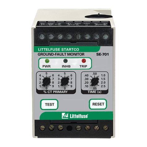
Startco SE-601 User manual

SE-601 MANUAL
DC GROUND-FAULT MONITOR
JULY 4, 2002
REVISION 0
Copyright © 2002 by Startco Engineering Ltd.
All rights reserved.
Publication: SE-601-M
Document: S95-C601-00000
Printed in Canada.

Blank Page

Startco Engineering Ltd. Page i
SE-601 DC Ground-Fault Monitor Rev. 0
Pub. SE-601-M, July 4, 2002.
TABLE OF CONTENTS PAGE
Table of Contents...................................................................i
List of Figures ........................................................................i
List of Tables..........................................................................i
1. General........................................................................1
2. Operation....................................................................1
2.1 Configuration-Switch Settings.....................................1
2.1.1 Relay Operating Mode ...................................1
2.1.2 Autoreset.........................................................1
2.2 Front-Panel Controls....................................................1
2.2.1 Trip Level .......................................................1
2.2.2 Trip Time........................................................1
2.2.3 Reset ...............................................................1
2.2.4 Test .................................................................1
2.3 Front-Panel Indication..................................................1
2.3.1 Power..............................................................1
2.3.2 Trip .................................................................1
2.4 Analog Output..............................................................3
3. Installation..................................................................3
4. Technical Specifications ............................................3
4.1 SE-601..........................................................................3
4.2 SE-GRM.......................................................................4
5. Ordering Information................................................4
LIST OF FIGURES
FIGURE PAGE
1 SE-601 Outline and Mounting Details........................2
2 Typical Connection Diagram ......................................3
3 SE-GRM Ground-Reference Module .........................5
4 PMA-55 Panel-Mount Adapter...................................6
LIST OF TABLES
TABLE PAGE
1 SE-601 Trip Levels and Fault Values .........................1
DISCLAIMER
Specifications are subject to change without notice.
Startco Engineering Ltd. is not liable for contingent or
consequential damages, or for expenses sustained as a
result of incorrect application, incorrect adjustment, or a
malfunction.

Blank Page

Startco Engineering Ltd. Page 1
SE-601 DC Ground-Fault Monitor Rev. 0
Pub. SE-601-M, July 4, 2002.
1. GENERAL
The SE-601 is a microprocessor-based ground-fault
monitor for ungrounded dc systems. Its output relay can
operate in the fail-safe or non-fail-safe mode for
undervoltage or shunt-trip applications, and the output
contacts are isolated for use in independent control circuits.
Additional features include LED and fluorescent-flag
indication, front-panel and remote reset, self test, 0 to 5-V
analog output, digital selector switches, and autoreset or
latching trips. The SE-601 can be DIN-rail, surface, or
panel mounted.
Ground-fault current is sensed using an SE-GRM
Ground-Reference Module—a resistor network that limits
ground-fault current to 25 mA. The trip level of the ground-
fault circuit is selectable from 1 to 20 mA. Trip time is
selectable from 0.05 to 2.5 s.
2. OPERATION
2.1 CONFIGURATION-SWITCH SETTINGS (See Fig. 1)
2.1.1 RELAY OPERATING MODE
The SE-601 has one output relay with isolated normally
open and normally closed contacts. The relay contacts
(terminals 13, 14, 15, and 16) are shown with the SE-601
de-energized. Switch 1 is used to set the operating mode of
the output relay. In the fail-safe mode, the output relay
energizes and the contacts change state when the SE-601 is
energized and remain in that state unless the ground-fault
circuit trips or the SE-601 is de-energized. In the non-fail-
safe mode, the output contacts do not change state when the
SE-601 is energized or de-energized—the output relay only
energizes when a trip occurs.
2.1.2 AUTORESET
Switch 2 is used to select autoreset or latching trips. See
2.2.3.
2.2 FRONT-PANEL CONTROLS
2.2.1 TRIP LEVEL
The LEVEL (mA) selector switch is used to set the
ground-fault trip level.
Ground-fault current is a function of fault resistance,
system voltage, and the SE-GRM Ground-Reference
Module. Table 1 lists the SE-601 trip levels and fault-
resistance values for 24-, 48-, 125-, and 250-Vdc systems.
TABLE 1. SE-601 TRIP LEVELS AND
FAULT-RESISTANCE VALUES
FAULT RESISTANCE (kΩ)
TRIP
LEVEL
(mA)
24 Vdc
SYSTEM
SE-GRM024
48 Vdc
SYSTEM
SE-GRM048
125 Vdc
SYSTEM
SE-GRM125
250 Vdc
SYSTEM
SE-GRM250
1
2
3
4
5
6
8
10
15
20
11.5
5.5
3.5
2.5
1.9
1.5
1.0
0.7
0.3
0.1
22.3
11.0
7.0
5.0
3.8
3.0
2.0
1.4
0.6
0.2
60.0
28.7
18.3
13.1
10.0
7.9
5.3
3.7
1.6
0.6
120.0
57.5
36.6
26.2
20.0
15.8
10.6
7.5
3.3
1.2
2.2.2 TRIP TIME
The TIME (s) selector switch is used to set the ground-
fault trip time.
2.2.3 RESET
The reset circuit responds only to a momentary closure so
that a jammed or shorted switch will not maintain a reset
signal. The front-panel RESET switch is disabled when
remote-reset terminals 6 and 7 are shorted.
If Switch 2 is in the LATCHING position, a trip remains
latched until the RESET switch is pressed, the remote-reset
terminals are momentarily shorted, or the supply voltage is
cycled. Cycling the supply voltage will not reset (black) the
fluorescent flag.
If Switch 2 is in the AUTORESET position, a trip will
reset when the fault is removed. The fluorescent flag will
not reset until the RESET switch is pressed or the remote-
reset terminals are momentarily shorted. Cycling the supply
voltage will not reset the fluorescent flag unless the remote-
reset terminals are shorted.
2.2.4 TEST
The TEST switch is used to test the ground-fault circuit,
trip indication, and the output relay. When the TEST switch
is pressed for one second the circuit will trip, both "–" and
"+" FAULT LED’s will illuminate, the fluorescent flag will
be set (red), and the output relay will operate.
2.3 FRONT-PANEL INDICATION
2.3.1 POWER
The green LED labeled PWR indicates presence of the
supply voltage.
2.3.2 TRIP
The FAULT LED's and the fluorescent flag labeled TRIP
indicate a ground-fault trip. The "–" FAULT LED indicates
a ground-fault on the negative dc bus. The "+" FAULT
LED indicates a ground-fault on the positive dc bus.

Startco Engineering Ltd. Page 2
SE-601 DC Ground-Fault Monitor Rev. 0
Pub. SE-601-M, July 4, 2002.
FIGURE 1. SE-601 Outline and Mounting Details.

Startco Engineering Ltd. Page 3
SE-601 DC Ground-Fault Monitor Rev. 0
Pub. SE-601-M, July 4, 2002.
2.4 ANALOG OUTPUT
The non-isolated, 0 to 5-V analog output indicates
ground-fault current. The output is 5 V when ground-fault
current is 22 mA.
3. INSTALLATION
Connect the SE-601 DC Ground-Fault Monitor and
SE-GRM Ground-Reference Module as shown in Fig. 2.
Remove the connection to terminals 5 and 9 for
dielectric-strength testing—all inputs and outputs have
ANSI/IEEE C37.90 surge-protection circuits that conduct
above 300 Vac.
4. TECHNICAL SPECIFICATIONS
4.1 SE-601
Supply:
0U Option............55 to 275 Vac, 50/60 Hz, 3.5 VA
75 to 275 Vdc, 2.0 W
0D Option............9 to 36 Vdc, 3.0 W
0T Option.............30 to 70 Vdc, 3.0 W
Dimensions:
Height.................................75 mm (3.0")
Width..................................55 mm (2.2")
Depth..................................115 mm (4.5")
Shipping Weight........................0.45 kg (1 lb.)
Trip-Level Settings....................1, 2, 3, 4, 5, 6, 8, 10, 15,
and 20 mA
Trip-Time Settings.....................0.05, 0.10, 0.20, 0.30, 0.40,
0.50, 1.0, 1.5, 2.0, and 2.5 s
Accuracies:
Trip Level...........................10% of setting or
0.5 mA, whichever is less
Trip Time ...........................10% of setting or
20 ms, whichever is less
Operating Mode.........................Latching or Autoreset
Analog Output:
Range..................................0 to 5 V, 0.23 V per mA
Output Impedance..............220 Ω
FIGURE 2. Typical Connection Diagram.

Startco Engineering Ltd. Page 4
SE-601 DC Ground-Fault Monitor Rev. 0
Pub. SE-601-M, July 4, 2002.
Reset...........................................Front-Panel Switch and
Remote, N.O. Contact
Functional Test...........................Front-Panel Switch
Output Relay:
CSA/UL Rating .................8 A resistive,
250 Vac/30 Vdc
Contact Configuration .......Isolated N.O. and N.C.
Operating Mode..................Fail-Safe or Non-Fail-Safe
Supplemental Contact Ratings:
Make/Carry 0.2 s ................20 A
Break:
dc.................................30 W resistive,
15 W inductive
(L/R = 0.4 s)
ac .................................2000 VA resistive
1400 VA inductive
(PF = 0.4)
Subject to maximums of 8 A and 250 V (ac or dc).
Environment:
Operating Temperature.......-40 to 60°C
Storage Temperature...........-55 to 80°C
Humidity.............................85% Non-Condensing
Surge Withstand.........................ANSI/IEEE 37.90.1-1989
(Oscillatory and Fast
Transient)
4.2 SE-GRM
Nominal Current........................12.5 mA
Maximum Fault Current............25 mA
Duty Cycle.................................Continuous
Dimensions: (for units listed below)
Height.................................105.0 mm (4.13")
Width..................................40.0 mm (1.57")
Depth..................................41.5 mm (1.63")
Shipping Weight........................300 g (0.7 lb)
Environment:
Operating Temperature......-40 to 60°C
Storage Temperature..........-55 to 80°C
Humidity.............................85% Non-Condensing
5. ORDERING INFORMATION
SE-601-0 — U Universal ac/dc Supply
D 9- to 36-Vdc Supply
T 30- to 70-Vdc Supply
SE-GRM024....Ground-Reference Module for 24-Vdc
system.
SE-GRM048....Ground-Reference Module for 48-Vdc
system.
SE-GRM125....Ground-Reference Module for 125-Vdc
system.
SE-GRM250....Ground-Reference Module for 250-Vdc
system.
Consult factory for other ground-reference modules.
PMA-55.......... Panel-Mount Adapter (See Fig. 4)
Consult factory for custom mounting adapters.

Startco Engineering Ltd. Page 5
SE-601 DC Ground-Fault Monitor Rev. 0
Pub. SE-601-M, July 4, 2002.
FIGURE 3. SE-GRM Ground-Reference Module.

Startco Engineering Ltd. Page 6
SE-601 DC Ground-Fault Monitor Rev. 0
Pub. SE-601-M, July 4, 2002.
FIGURE 4. PMA-55 Panel-Mount Adapter.
Table of contents
Other Startco Monitor manuals
Popular Monitor manuals by other brands

novotechnik
novotechnik MAP 4000 Series Setup manual
Ikegami
Ikegami HQLM-1720WR Operation manual

Philips
Philips 24E1N5300HE user manual
Samsung
Samsung SyncMaster 2494HM quick start guide
Fujitsu
Fujitsu Plasmavision PDS4208W-B user manual
Atlantis Land
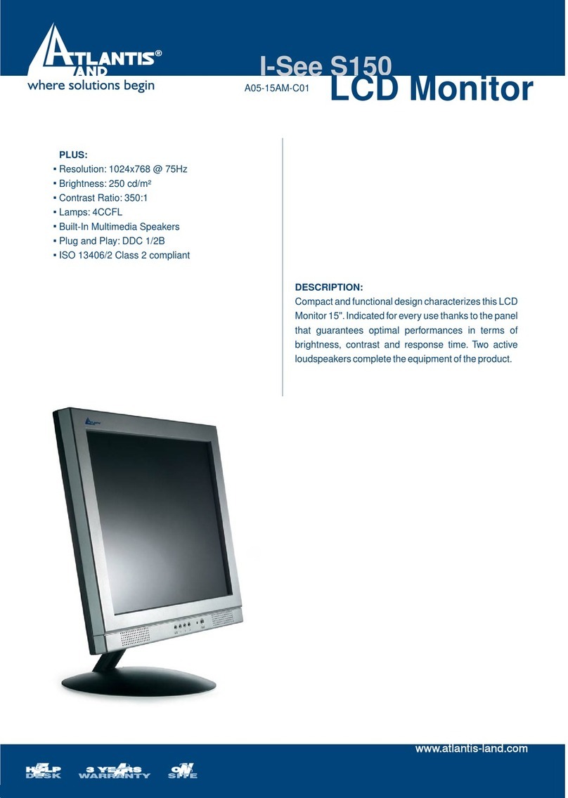
Atlantis Land I-See S150 LCD Monitor A05-15AM-C01 specification
