Startco SE-330HV User manual

406 Jessop Avenue Saskatoon, Saskatchewan Canada S7N 2S5 Ph: (306) 373-5505 Fx: (306) 374-2245 www.startco.ca
SE-330HV MANUAL
NEUTRAL-GROUNDING-RESISTOR MONITOR
MARCH 24, 2006
REVISION 0
NEUTRAL GROUNDING RESISTOR
MONITOR
STARTCO
ENGINEERING LTD.
SE-330HV
GF TRIP LEVEL
(% CT RATING)
V TRIP LEVEL
(S5 )
N
GF TRIP TIME ( )
CALIBRATED
POWER
REL K1AY
DIAGNOSTIC
0.1
2
0.2
4
0.3
6
0.4
8
0.5
10
0.7
15
1.0
2.0
40
3.0
60
5.0
80
10.0
100
Vx
RESET
GROUND
FAULT
TRIP
20
RESISTOR
FAULT
TRIP
Tx
Rx
S
100
300
500
650
850
1000
6000
10000
8500
4000
1700
1
Vx 2
Copyright 2006 Startco Engineering Ltd.
All rights reserved.
Publication: SE-330HV-M
Document: S95-C330-0H000
Printed in Canada.

Blank Page

Startco Engineering Ltd. Page i
SE-330HV Neutral-Grounding-Resistor Monitor Rev. 0
Pub. SE-330HV-M, March 24, 2006.
TABLE OF CONTENTS
PAGE
Table of Contents .............................................................. i
List of Figures ................................................................... i
List of Tables..................................................................... i
1. General ................................................................... 1
1.1 Modern Resistance-Grounded Systems ................... 1
1.2 SE-330HV NGR Monitoring ................................... 1
2. Operation................................................................ 2
2.1 Settings .................................................................... 2
2.1.1 GF Trip Time................................................ 2
2.1.2 GF Trip Level ............................................... 2
2.1.3 VNTrip Level ............................................... 2
2.1.4 Configuration Settings .................................. 3
2.1.4.1 Spare (S1) ........................................ 3
2.1.4.2 Trip-Relay Mode (S2)...................... 3
2.1.4.3 Ground-Fault-Trip Latch (S3) ......... 3
2.1.4.4 Resistor-Fault-Trip Latch (S4)......... 3
2.1.4.5 Sensing-Resistor Selection (S5)....... 3
2.1.4.6 Frequency (S6)................................. 3
2.1.4.7 Spare (S7) ........................................ 3
2.1.4.8 Upgrade Enable (S8)........................ 3
2.2 Calibration ............................................................... 3
2.3 Trip Indication and Reset......................................... 4
2.4 Remote Operation.................................................... 4
2.5 Relay K1 LED ......................................................... 4
2.6 Unit Healthy Output ................................................ 4
2.7 Diagnostic LED ....................................................... 4
2.8 Analog Output ......................................................... 5
3. Installation.............................................................. 5
3.1 SE-330HV ............................................................... 5
3.2 Sensing Resistor ...................................................... 5
3.3 Ground-Fault CT ................................................... 14
3.4 Isolated Ground Connection .................................. 17
4. Communications .................................................. 18
4.1 Local Communication Ports .................................. 18
4.1.1 Local Data Acquisition ............................... 18
4.1.2 Firmware Upgrade...................................... 18
4.2 Network Communications ..................................... 18
5. Troubleshooting ................................................... 19
6. Technical Specifications ...................................... 20
6.1 SE-330HV ............................................................. 20
6.2 Sensing Resistors ................................................... 21
6.3 Current Sensors...................................................... 21
7. Ordering Information ......................................... 21
8. Warranty .............................................................. 22
PAGE
9. Test Procedures ....................................................22
9.1 Resistor-Fault Tests................................................22
9.1.1 Calibration and Open Test..........................22
9.1.2 Voltage Test ...............................................22
9.2 Sensing-Resistor Test .............................................23
9.3 Analog-Output Test................................................23
9.4 Ground-Fault Performance Test .............................23
LIST OF FIGURES
FIGURE PAGE
1 Configuration Switches ............................................3
2 Analog-Output Connections.....................................5
3 SE-330HV Connection Diagram..............................6
4 SE-330HV Outline and Panel-Mounting Details......7
5 SE-330HV Outline and Surface-Mounting Details ..8
6 ER-15KV Sensing Resistor ......................................9
7 ER-25KV Sensing Resistor ....................................10
8 ER-35KV Sensing Resistor ....................................11
9 ER-72KV Sensing Resistor Outline .......................12
10 ER-72KV Sensing Resistor Mounting Details .......13
11 EFCT-1 Sensitive Ground-Fault Current
Sensor .................................................................14
12 SE-CS30-70 Sensitive Ground-Fault
Current Sensor....................................................15
13 EFCT-26 and SE-CS30-26 Sensitive Ground-
Fault Current Sensors .........................................16
14 RK-332 Remote Indication and Reset ....................17
15 Simplified Isolated-Ground Connection.................17
16 Ground-Fault-Test Circuit ......................................23
LIST OF TABLES
TABLE PAGE
1 Typical Values for Tripping Systems.......................2
2 Ground-Fault Trip Levels for Selected CT’s............2
3 RS-232 DB-9 Terminals.........................................18
4 Gound-Fault-Test Record.......................................23
DISCLAIMER
Specifications are subject to change without notice. Startco
Engineering Ltd. is not liable for contingent or
consequential damages, or for expenses sustained as a result
of incorrect application, incorrect adjustment, or a
malfunction.

Blank Page

Startco Engineering Ltd. Page 1
SE-330HV Neutral-Grounding-Resistor Monitor Rev. 0
Pub. SE-330HV-M, March 24, 2006.
1. GENERAL
1.1 MODERN RESISTANCE-GROUNDED SYSTEMS
A high-resistance-grounded system uses a neutral-
grounding resistor (NGR) with a low let-through current
to limit ground-fault current. High-resistance grounding
is gaining popularity because a ground-fault flash hazard
exists in low-resistance- or solidly grounded systems and
a ground-fault can result in substantial point-of-fault
damage. High-resistance grounding eliminates these
problems and modern ground-fault protection operates
reliably at these levels. Furthermore, the probability of an
arc-flash incident is significantly reduced in a high-
resistance-grounded system.
NGR selection depends on system charging current and
whether the system is an alarm-only or a tripping system.
Alarm-only systems are usually restricted to system
voltages up to 5 kV with NGR let-through currents of 5 A
or less. Occasionally, alarm-only systems up to 15 kV
and up to 10 A are used; however, they are not common
because a ground fault on such a system tends to escalate
to a phase-to-phase fault before the ground fault can be
located and cleared.
System charging current is the capacitive current that
flows to ground when a bolted ground fault occurs. This
current can be calculated or measured. For small systems,
the magnitude of charging current is typically ½ A per
1,000 kVA on low-voltage systems and 1 A per
1,000 kVA on medium-voltage systems.
In an alarm-only system or in a tripping system without
selective coordination, choose an NGR with a let-through
current larger than the system charging current and set
the pick-up current of ground-fault devices at or below
50% of the NGR let-through current.
In a tripping system with selective coordination, use
ground-fault devices with a definite-time characteristic to
achieve time coordination. Use the same pick-up current
for all ground-fault devices—this value must be larger
than the charging current of the largest feeder. Select an
NGR with a let-through current between five and ten
times the pick-up current of the ground-fault devices.
Do not use a grounding transformer with a low-voltage
resistor:
•The combined cost of a transformer and a low-
voltage resistor is more than the cost of a resistor
rated for line-to-neutral voltage.
•A transformer saturated by a ground fault through a
rectifier can make ground-fault protection
inoperative.
•Transformer inrush current up to twelve times rated
current can cause a ground-fault voltage larger than
expected.
•A parallel transformer winding makes it difficult to
monitor NGR continuity.
•A transformer can provide the inductance necessary
to cause ferroresonance if the NGR opens.
Following these guidelines will reduce the flash hazard,
reduce point-of-fault damage, achieve reliable ground-
fault protection, and ensure a stable system not subject to
ferroresonance.
1.2 SE-330HV NGR MONITORING
The SE-330HV is a microprocessor-based neutral-
grounding-resistor monitor that detects NGR failures and
ground faults in resistance-grounded systems. The
SE-330HV measures NGR resistance, NGR current, and
transformer or generator neutral-to-ground voltage. The
components required to monitor an NGR are an
SE-330HV, a 100- or 200-kΩER-series sensing resistor,
and a current transformer (CT).
The SE-330HV continuously measures NGR resistance
in an unfaulted system, and it will trip on resistor fault if
NGR resistance varies from its calibrated value. When a
ground fault occurs, voltage is present on the neutral and
NGR current will flow if the NGR is healthy. The
SE-330HV will trip on ground fault if fault current
exceeds the GF TRIP LEVEL setting for an interval
greater than the GF TRIP TIME setting. However, if the
NGR fails open during a ground fault, it is possible for
fault resistance to satisfy the NGR resistance
measurement. To detect this double-fault condition, the
SE-330HV measures neutral voltage. If neutral voltage
exceeds the VNTRIP LEVEL setting, and if NGR current
is less than 5% of the CT rating, the SE-330HV will trip
on resistor fault. If the resistor-fault circuit is tripped and
the neutral voltage exceeds the VNTRIP LEVEL setting
for an interval greater than the GF TRIP TIME setting,
the ground-fault circuit will also trip.
Ground-fault current is sensed by a CT with a 1- or 5-A
secondary, or by a sensitive CT (EFCT-x or
SE-CS30-x) with a 50-mA secondary. The trip level of
the ground-fault circuit is adjustable from 2 to 100% of
the CT rating and trip time is adjustable from 0.1 to 10.0
seconds.
The SE-330HV has four output relays. Relay K1 is the
trip relay. Relays K2 and K3 provide ground-fault and
resistor-fault indication. K4 is a solid-state relay that
provides UNIT HEALTHY indication. Relay K1 can
operate in the fail-safe or non-fail-safe mode for
undervoltage or shunt-trip applications.
Additional features include LED and fluorescent-flag
trip indication, trip memory, front-panel and remote reset,
4–20-mA analog output, RS-232 local communications,
optical local communications, and optional network
communications.

Startco Engineering Ltd. Page 2
SE-330HV Neutral-Grounding-Resistor Monitor Rev. 0
Pub. SE-330HV-M, March 24, 2006.
2. OPERATION
2.1 SETTINGS
2.1.1 GF TRIP TIME
GF TRIP TIME (definite time) is adjustable from 0.1 to
10.0 seconds. Time-coordinated ground-fault protection
requires this setting to be longer than the trip times of
downstream ground-fault devices.
2.1.2 GF TRIP LEVEL
The SE-330HV uses a Discrete-Fourier Transform
(DFT) algorithm to measure the fundamental component
of NGR current.
Choose an NGR let-through current and a ground-fault
trip level according to the guidelines in Section 1.1.
Set the ground-fault trip level as a percentage (2, 4, 6, 8,
10, 15, 20, 40, 60, 80, or 100) of the CT-primary rating.
Inputs are provided for 5-, 1-, and 0.05-A-secondary
CT’s. Typical values for 15-, 25-, and 100-A tripping
systems are shown in Table 1. Ground-fault trip levels
for selected CT’s are shown in Table 2.
2.1.3 VNTRIP LEVEL
The SE-330HV uses a DFT algorithm to measure the
fundamental component of neutral voltage.
Calculate the voltage across the NGR when NGR
current is equal to the pick-up current of the ground-fault
circuit. Set the VNTRIP LEVEL at the next largest
value. The VNTRIP LEVEL range is 100 to 10,000 V
with switch S5 in the 100-kΩ(Vx1) position, and the
range is 200 to 20,000 V with switch S5 in the 200-kΩ
(Vx2) position. See Fig. 1 and Section 2.1.4.5.
If neutral voltage is greater than the VNTRIP LEVEL
setting for 12 seconds and ground-fault current is less
than 5% of the CT rating, the SE-330HV will trip on
resistor fault. If the resistor-fault circuit is tripped and
the neutral voltage exceeds the VNTRIP LEVEL setting
for an interval greater than the GF TRIP TIME setting,
the ground-fault circuit will also trip.
Typical values for 15-, 25- and 100-A tripping systems
are shown in Table 1.
NOTE:A resistor-fault trip is held off if the ground-
fault current is above 5% of the CT rating.
TABLE 1. TYPICAL VALUES FOR TRIPPING SYSTEMS
System
Voltage
Neutral-Grounding
Resistor
Sensing
Resistor
Ground-Fault
Trip Level
VNTrip
Level
(Volts)
Current
(Amperes)
Resistance
(Ohms)
Model Resistance
(Switch S5 Setting) (Amperes) (Volts)
7,200
14,400
7,200
14,400
25,000
35,000
72,000
15
15
25
25
25
25
100
277
554
166
332
577
808
420
ER-15KV
ER-15KV
ER-15KV
ER-15KV
ER-25KV
ER-35KV
ER-72KV
100 kΩ
100 kΩ
100 kΩ
100 kΩ
100 kΩ
100 kΩ
200 kΩ
3.0
3.0
5.0
5.0
5.0
5.0
20.0
850
1,700
850
1,700
4,000
6,000
6,000 x 2 = 12,000
TABLE 2. GROUND-FAULT TRIP LEVELS FOR SELECTED CT’S
GF TRIP
LEVEL
(%)
EFCT-x
5:0.05
(Amperes)
SE-CS30-x
30:0.05
(Amperes)
50:1
50:5
(Amperes)
100:1
100:5
(Amperes)
200:1
200:5
(Amperes)
400:1
400:5
(Amperes)
2
4
6
8
10
15
20
40
60
80
100
0.10
0.20
0.30
0.40
0.50
0.75
1.00
2.00
3.00
4.00
5.00
0.60
1.20
1.80
2.40
3.00
4.50
6.00
12.0
18.0
24.0
30.0
*
*
*
*
5
7.5
10
20
30
40
50
*
*
*
8
10
15
20
40
60
80
100
*
*
12
16
20
30
40
80
120
160
200
*
16
24
36
40
60
80
160
240
320
400
* Setting not recommended.
Startco Engineering Ltd. Page 3
SE-330HV Neutral-Grounding-Resistor Monitor Rev. 0
Pub. SE-330HV-M, March 24, 2006.
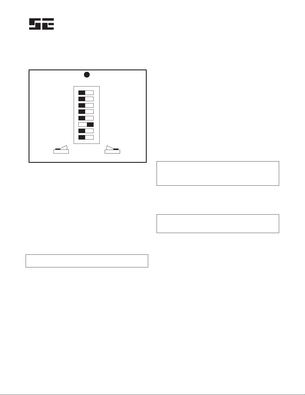
2.1.4 CONFIGURATION SETTINGS
Eight configuration switches (S1 to S8) and a
calibration push button are located behind the access
cover on the front panel. See Fig. 1.
LATCHING RF TRIP
LATCHING TRIPGF
200 kW
50 Hz
SPARE
FAIL-SAFE
SPARE
RUN
NON-LATCHING RF TRIP
NON-LATCHING GF TRIP
100 kW
60 Hz
NON-FAIL-SAFE
UPGRADE
S1
S2
S3
S4
S5
S6
S7
S8
CALIBRATION PUSH BUTTON
NOTE: DEFAULT SETTINGS SHOWN.
CAL
FIGURE 1. Configuration Switches.
2.1.4.1 SPARE (S1)
2.1.4.2 TRIP-RELAY MODE (S2)
Set switch S2 to select the operating mode of trip relay
K1. In the non-fail-safe mode, relay K1 energizes and its
contact closes when a trip occurs. The non-fail-safe mode
can be used to trip shunt-trip circuit breakers. In the non-
fail-safe mode, trips are reset when supply voltage is
cycled.
In the fail-safe mode, relay K1 energizes and its contact
closes if there are no trips. Contacts open if there is a trip, a
loss of supply voltage, or a processor failure. In the fail-safe
mode, trips are not reset when supply voltage is cycled.
NOTE:Switch S2 does not affect the operation of the
ground-fault and resistor-fault indication relays.
2.1.4.3 GROUND-FAULT-TRIP LATCH (S3)
Set switch S3 to select latching or non-latching ground-
fault-circuit operation. See Section 2.3.
2.1.4.4 RESISTOR-FAULT-TRIP LATCH (S4)
Set switch S4 to select latching or non-latching resistor-
fault-circuit operation. See Section 2.3
2.1.4.5 SENSING-RESISTOR SELECTION (S5)
Set switch S5 to the resistance of the sensing resistor. For
the ER-15KV, ER-25KV, and ER-35KV, select 100 kΩ.
For the ER-72KV select 200 kΩ. Switch S5 sets the
VNTRIP LEVEL range. See Section 2.1.3.
2.1.4.6 FREQUENCY (S6)
Set switch S6 to 50 or 60 Hz to tune the digital filter to
the line frequency of the monitored system.
2.1.4.7 SPARE (S7)
2.1.4.8 UPGRADE ENABLE (S8)
Set switch S8 to RUN for normal operation or to
UPGRADE to enable firmware upgrades. Changes in
switch S8 settings are recognized only when supply
voltage is cycled. Protection is disabled after supply
voltage is cycled with S8 in the UPGRADE position.
See Section 4.1.2.
2.2 CALIBRATION
The SE-330HV measures the resistance change of the
NGR relative to the NGR-resistance value determined at
the time of calibration. Calibrate the SE-330HV on new
installations, if the NGR is changed, or if the sensing
resistor is changed.
NOTE:If the SE-330HV is not calibrated and is supplied
from the load side of the breaker (non-fail-safe mode),
calibrate within 12 seconds of power-up or it may trip and
interrupt its supply.
The CALIBRATION push button is located behind the
access cover on the front panel, and it is recessed to
prevent inadvertent activation.
NOTE:Calibration must be performed with the
SE-330HV connected to the sensing resistor and NGR of
the installed system.
To calibrate, press and hold the CALIBRATION push
button until the green CALIBRATED LED turns off and
returns to on (if the LED is already off, press and hold
until the LED turns on). Calibration takes approximately
two seconds. If calibration is not successful, a resistor-
fault trip occurs, the RESISTOR FAULT TRIP LED will
be on, the CALIBRATED LED will be off, and the
DIAGNOSTIC LED will flash the calibration-error code.
See Section 2.7.
If latching resistor fault (switch S4) is selected, the
calibration-error code flashes until RESET is pressed
even if the CALIBRATED LED is on.
The calibration value is stored in non-volatile memory.

Startco Engineering Ltd. Page 4
SE-330HV Neutral-Grounding-Resistor Monitor Rev. 0
Pub. SE-330HV-M, March 24, 2006.
2.3 TRIP INDICATION AND RESET
Red LED's, fluorescent flags, and indication relays
indicate ground-fault and resistor-fault trips—indication
relays K2 and K3 are energized on trip. When a trip occurs
with latching operation selected, the SE-330HV remains
tripped until reset. See Sections 2.1.4.3 and 2.1.4.4.
Terminals 15 and 16 are provided for remote reset as shown
in Fig. 3. The reset circuit responds only to a momentary
closure so that a jammed or shorted switch does not prevent
a trip. The front-panel RESET switch is inoperative when
terminal 15 is connected to terminal 16. If non-latching
operation is selected, trips and corresponding indication
automatically reset when the fault clears.
The red DIAGNOSTIC LED annunciates latched
calibration-error and remote trips. See Section 2.7.
Fluorescent flags retain their state when supply voltage
is removed. When supply voltage is applied with switch
S2 set to FAIL-SAFE, the SE-330HV returns to its state
prior to loss of supply voltage. When supply voltage is
applied with switch S2 set to NON-FAIL-SAFE,
SE-330HV trips are reset; however, fluorescent flags are
not reset. When a local, remote, or network reset is issued,
both trip LED's will flash if they are off.
Resistor-fault-trip reset can take up to one second.
2.4 REMOTE OPERATION
Relays K2 and K3 can be used for remote indication,
and terminals 15 and 16 are provided for remote reset.
RK-332 Remote Indication and Reset components are
shown in Fig. 14. Connect them as shown in Fig. 3.
RK-332 components are not polarity sensitive.
Network-enabled SE-330HV’s can be remotely tripped
and reset by the network master. The red DIAGNOSTIC
LED indicates a network-initiated trip. See Section 2.7.
Refer to the appropriate SE-330 communications manual.
2.5 RELAY K1 LED
The yellow RELAY K1 LED follows the state of relay
K1 and is on when K1 is energized (contact closed).
2.6 UNIT HEALTHY OUTPUT
UNIT HEALTHY relay K4 is energized when the
processor is operating. It can be ordered with N.O. or
N.C. contacts. See Section 7.
NOTE:The output changes state momentarily during a
processor reset.
NOTE:K4-contact rating is 100 mA maximum.
2.7 DIAGNOSTIC LED
The DIAGNOSTIC LED is used to annunciate trips
without individual LED indication. The number of short
LED pulses between two long pulses indicates the cause
of the trip.
Calibration-Error Trip (1 short):
The calibration resistance of the NGR is outside the
calibration range. See Section 6.1.
Remote Trip (2 short):
The SE-330HV has been tripped by a remote-trip
command from the communications interface.
EEPROM-Error Trip (3 short):
An EEPROM error has been detected.
A/D-Converter-Error Trip (4 short):
An A/D-converter error has occurred.
Software-Interrupt Trip (5 short):
CPU reset was caused by a software interrupt.
Illegal-Opcode Trip (6 short):
CPU reset was caused by an illegal Opcode.
Watchdog Trip (7 short):
CPU reset was caused by the watchdog.
Clock-Failure Trip (8 short):
CPU reset was caused by an internal clock failure.
Trap-Code Trip (9 short):
This code is displayed if the supply is cycled after one
of the previous four errors occurred.
Resistor-fault trips occur with all of the above trips.
Ground-fault trips occur with all of the above trips except
the calibration-error trip and the A/D-converter-error trip.
See Troubleshooting Section 5.

Startco Engineering Ltd. Page 5
SE-330HV Neutral-Grounding-Resistor Monitor Rev. 0
Pub. SE-330HV-M, March 24, 2006.
2.8 ANALOG OUTPUT
An isolated 4–20-mA output indicates NGR current
with full-scale output corresponding to the CT rating. An
internal 24-Vdc supply allows the analog output to be
connected as a self-powered output. Power from an
external supply is required for loop-powered operation.
See Fig. 2.
FIGURE 2. Analog-Output Connections.
3. INSTALLATION
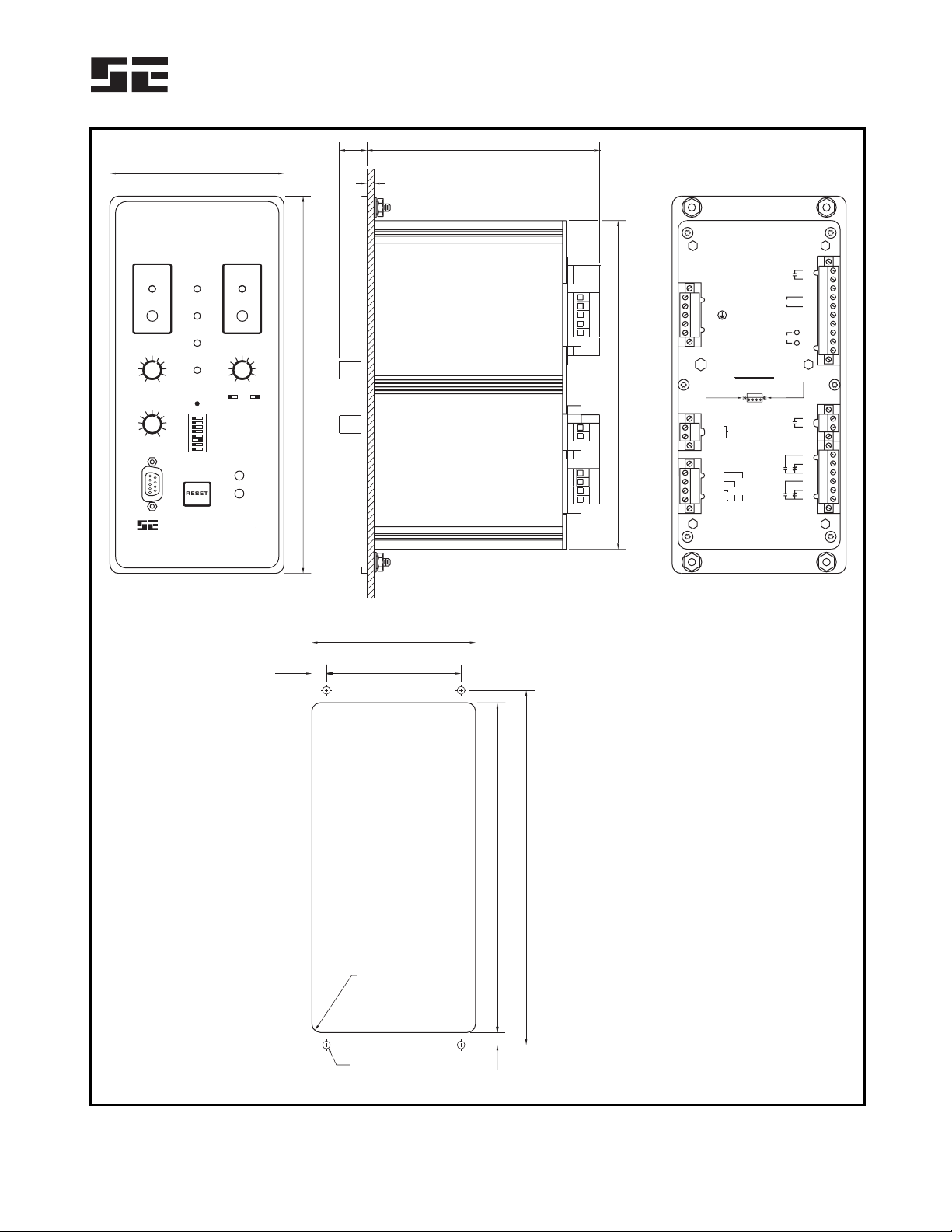
3.1 SE-330HV
Outline and panel-cutout dimensions for the SE-330HV
are shown in Fig. 4. To panel mount the SE-330HV,
insert it through the panel cutout and secure it with four
8-32 locknuts and flat washers (included).
All connections to the SE-330HV are made with plug-
in, wire-clamping terminal blocks. Each plug-in terminal
block can be secured to the monitor by two captive screws
for reliable connections.
Outline dimensions and mounting details for surface
mounting the SE-330HV are shown in Fig. 5. Fasten the
surface-mount adapter to the mounting surface and make
connections to the adapter terminal blocks. Follow Fig. 5
instructions to mount or remove the SE-330HV.
Ground terminal 7 (G) and connect terminal 6 (R) to
the sensing-resistor R terminal.
Use terminal 1 (L1) as the line terminal on ac systems,
or the positive terminal on dc systems. Use terminal 2
(L2/N) as the neutral terminal on ac systems or the
negative terminal on dc systems. Connect terminal
3 ( ) to ground. Connect terminal 4 (SPG) to terminal
5 (SPGA). Remove the terminal-4-to-5 connection for
dielectric-strength testing.
NOTE: When the terminal-4-to-5 connection is removed,
protective circuits inside the SE-330HV are disconnected
to allow dielectric strength testing of a control panel
without having to disconnect wiring to the SE-330HV.
Ensure that the terminal-4-to-5 connection is replaced
after testing.
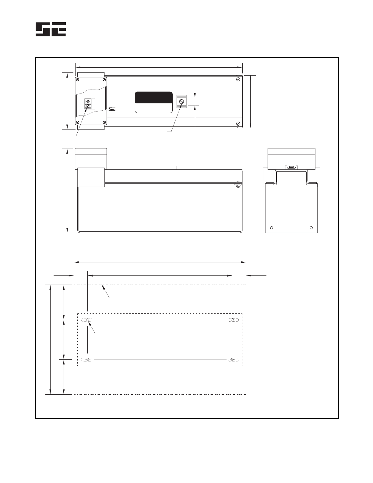
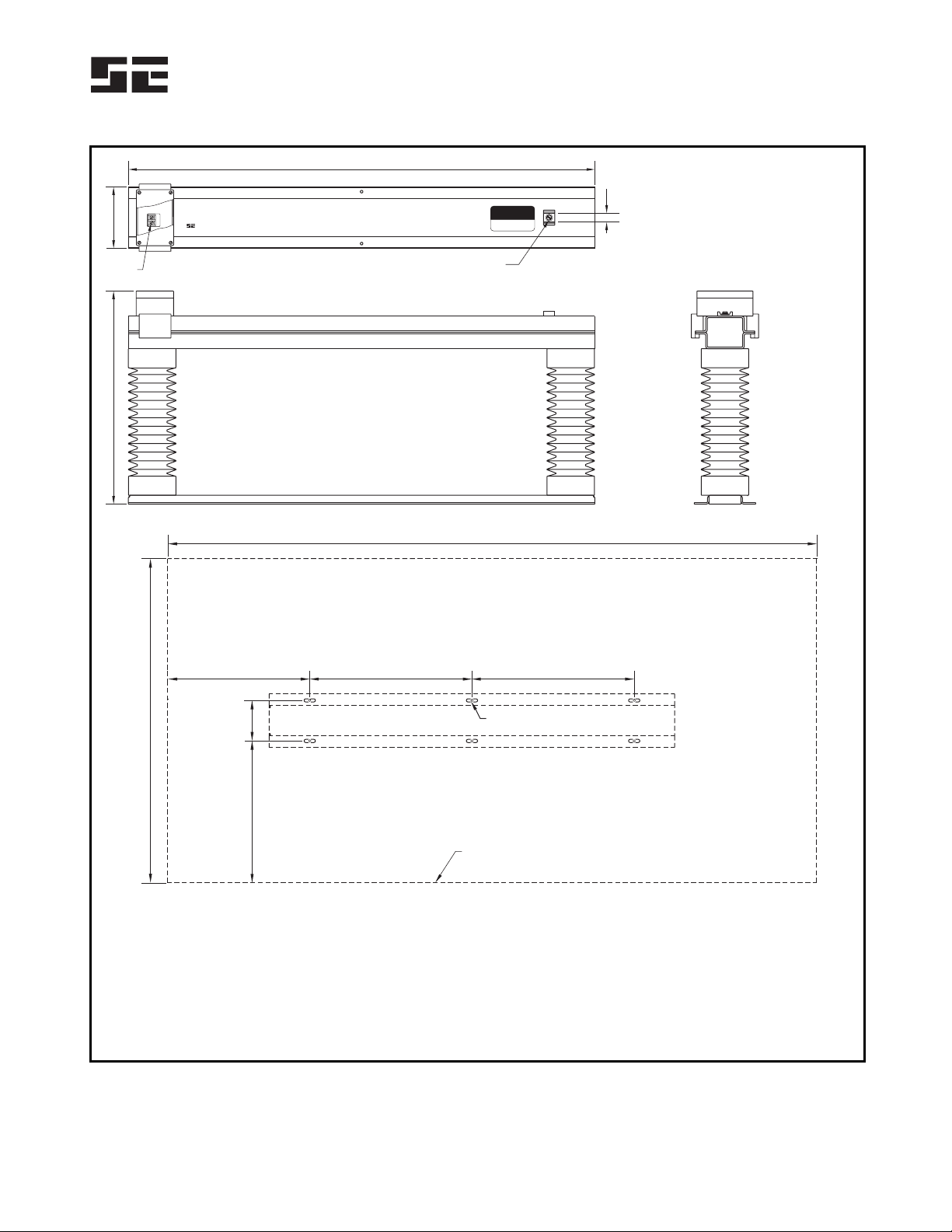
3.2 SENSING RESISTOR
Outline and mounting details for ER-15KV, ER-25KV,
ER-35KV and ER-72KV sensing resistors are shown in
Figs. 6, 7, 8, 9 and 10. Locate the NGR and the sensing
resistor near the transformer or generator. Ground sensing-
resistor terminal G. Pass the sensing-resistor-to-neutral
conductor and the NGR-to-neutral conductor through the
ground-fault-CT window as shown in Fig. 3. Separately
connect sensing-resistor terminal N and the NGR to the
neutral to include neutral connections in the monitored loop.
If a ground fault in the sensing-resistor conductor is
unlikely, a minimal loss of protection will result if it does
not pass through the ground-fault-CT window. See Note 3
in Fig. 3.
CAUTION:Voltage at terminal N rises to line-to-neutral
voltage when a ground fault occurs. The same clearances
are required for sensing resistors as for NGR’s.
NOTE:The neutral-to-sensing-resistor-terminal-N connection
is not a neutral conductor as defined in Canadian
Electrical Code Section 10-1108 and National Electrical
Code Section 250.36(B). It is not required to be 8 AWG
or larger. Since current through this conductor is always
less than 250 mA, a 14 AWG conductor insulated to the
system voltage is more than sufficient.

Startco Engineering Ltd. Page 6
SE-330HV Neutral-Grounding-Resistor Monitor Rev. 0
Pub. SE-330HV-M, March 24, 2006.
NOTES:
USE SEPARATE LUG TO CONNECT SENSING-
RESISTOR TERMINAL N TO NEUTRAL.
LOCATE THESE COMPONENTS NEAR
TRANSFORMER OR GENERATOR.
ALTERNATE SENSING-RESISTOR
TERMINAL-N CONNECTION.
VOLTAGE BETWEEN SENSING-RESISTOR
TERMINALS R AND G IS LIMITED TO 100 V BY
INTERNAL CLAMP.
SEE SECTION 3.4 FOR ISOLATED-GROUND
CONNECTION.
ALTERNATE CT LOCATION.
RELAY CONTACTS SHOWN WITH SE-330HV
DE-ENERGIZED.
LOOP-POWERED CONNECTION USES
TERMINALS 19 AND 20 ONLY.
RS232 PIN 4 (DTR), PIN 7 (RTS), AND
PIN 9 (RI) NOT CONNECTED.
REFER TO APPROPRIATE SE-330
COMMUNICATIONS INTERFACE MANUAL.
2.
1.
3.
4.
6.
5.
7.
8.
9.
10.
11.
EFCT-X
OR
SE-CS30-X
NGR
ER-SERIES
SENSING
RESISTOR
N
NEUTRAL
NOTE 1
NOTE 2
NOTE 3
NOTE 4
NOTE 6
NOTE 5
RG
1S5C
981011
SE-330HV
XXX:5
ALTERNATE CT
CONNECTIONS
XXX:1 OR
NOTE 7
NOTE 9
NOTE 8
L/+ SUPPLY
7
23
24
25
27
28
2
1
29
26
22
L1 L2/N
13
12
14 NC
UNIT HEALTHY
GF GROUND
FAULT
RF RESISTOR
FAULT
N/- SUPPLY
C
K1
K4
K3
K2
G
SE-330HV
5
4
3
SPGA
SPG
+24V
ANALOG OUTPUT
0V
DCD
DSR
CTS
RxD
TxD
Tx
Rx
RESET
18
19
20
21
1
6
8
2
3
5
REMOTE
RESET
17
16
15
+
–
SELF POWERED
4-20 mA
OUTPUT
S15
5A
1A
EFCT
C
6
R
891011
RS232 COM
NOTE 10
OPTICAL
COM
OPTIONAL
NETWORK COM
NOTE 11
TRANSFORMER
OR GENERATOR
OPTIONAL N.C. AVAILABLE.
FIGURE 3. SE-330HV Connection Diagram.
Startco Engineering Ltd. Page 7
SE-330HV Neutral-Grounding-Resistor Monitor Rev. 0
Pub. SE-330HV-M, March 24, 2006.
98.3
132.0
92.7
76.28.2
16.0
212.6
185.4
200.0
186.0
7.0
(3.87)
(5.20)
(3.65)
(3.00)(0.32)
(0.63)
(8.37)
(7.30)
(7.87)
(7.32)
(0.28)
FRONT VIEW
NOTE 2
SIDE VIEW
PANEL-MOUNT CUTOUT
REAR VIEW
PANEL THICKNESS
1.6 (0.06) TO 4.8 (0.19)
NOTES:
1. DIMENSIONS IN MILLIMETRES (INCHES).
2. SE-330HV SHOWN WITHOUT SWITCH
ACCESS COVER.
4.4 (0.173) DIA
4 LOCATIONS
R=4.8 (0.19)
MAXIMUM
1
4
2
3
5
-
-
-
-
-
-
-
-
-
-
-
-
-
-
-
-
L1
L2/N
SPG
SPGA
RSENSING
RESISTOR
G
S
1
55
A
1
A
E
F
C
T
C
6
7
10
8
11
9
12
13
14
15
16
17
18
19
20
21
UNIT
HEALTHY K4
NC
24V
0V
RESET
ANALOG OUTPUT
27
28
29
22
23
24
25
26
K3
K2
GROUND
FAULT
RESISTOR
FAULT
K1
ATTENTION
DISENGAGE CAPTIVE RETAINING
SCREWS BEFORE REMOVING
PLUG-IN TERMINAL BLOCKS
+
+
-
NEUTRAL GROUNDING RESISTOR
MONITOR
STARTCO
ENGINEERING LTD.
SE-330HV
GF TRIP LEVEL
(% CT RATING)
V TRIP LEVEL
(S5 )
N
GF TRIP TIME ( )
CALIBRATED
POWER
REL K1AY
DIAGNOSTIC
.10
2100
300
.20
4
.30
6
.40
8
500
650
850
.50
10
.70
15 1000
1.0
2.0
40
6000
3.0
60
5.0
80
10.0
100 10000
21
Vx Vx
8500
4000
1700
RESET
20
Tx
Rx
S
CAL
4
5
6
7
8
3
2
1
GROUND
FAULT
TRIP
RESISTOR
FAULT
TRIP
FIGURE 4. SE-330HV Outline and Panel-Mounting Details.

Startco Engineering Ltd. Page 8
SE-330HV Neutral-Grounding-Resistor Monitor Rev. 0
Pub. SE-330HV-M, March 24, 2006.
(1.00)
25.4
(2.50)
63.5
215.9 5.0
(8.50) (0.20)
MOUNTING DETAIL
BEZEL OUTLINE
ADAPTER PANEL OUTLINE
(NOTE 2)
NOTES:
MONITOR INSTALLATION
MONITOR REMOVAL
1. DIMENSIONS IN MILLIMETRES (INCHES).
2. MOUNTING SCREWS: M4 OR 8-32 PANHEAD.
LOOSEN RETAINER SCREWS, MOVE RETAINERS
OUTWARD, AND TIGHTEN RETAINER SCREWS.
MATE MONITOR WITH ADAPTER PLUG-IN TERMINALS.
LOOSEN RETAINER SCREWS TO LET RETAINERS
SNAP OVER MONITOR BACKPLATE.
LOOSEN RETAINER SCREWS, SLIDE RETAINERS AWAY
FROM MONITOR BODY, AND TIGHTEN RETAINER SCREWS.
PULL MONITOR FORWARD.
1.
2.
3.
1.
2.
ENSURE THAT RETAINERS ARE AGAINST MONITOR
BODY AND TIGHTEN RETAINER SCREWS.
98.3 138.0
114.3
8.0
(3.87) (5.43)
(4.50)
(0.31)
212.6
225.4
6.4
(8.37)
(8.87)
(0.25)
FRONT VIEW SIDE VIEW
FRONT VIEW
SE-330-SMA
RETAINER SCREW
RETAINER
NEUTRAL GROUNDING RESISTOR
MONITOR
STARTCO
ENGINEERING LTD.
SE-330HV
GF TRIP LEVEL
(% CT RATING)
V TRIP LEVEL
(S5 )
N
GF TRIP TIME ( )
CALIBRATED
POWER
REL K1AY
DIAGNOSTIC
.10
2100
300
.20
4
.30
6
.40
8
500
650
850
.50
10
.70
15 1000
1.0
2.0
40
6000
3.0
60
5.0
80
10.0
100 10000
21
Vx Vx
8500
4000
1700
RESET
20
Tx
Rx
S
1 1
4 4
2 2
3 3
5 5
-
-
-
-
-
-
-
-
-
-
-
-
-
-
-
-
L1
L2/N
SPG
SPGA
R
SENSING
RESISTOR G
S
1
5
5
A
1
A
E
F
C
T
C
6 6
7 7
10 10
8 8
1111
9 9
12
13
14
15
16
17
18
19
20
21
UNIT
HEALTHY
K4
NC
24V
0V
RESET
PULSE ENABLE
ANALOG OUTPUT
27
28
29
22
23
24
25
26
K3
K2
GROUND
FAULT
RESISTOR
FAULT
K1
+
+
-
GROUND
FAULT
TRIP
RESISTOR
FAULT
TRIP
FIGURE 5. SE-330HV Outline and Surface-Mounting Details.
Startco Engineering Ltd. Page 9
SE-330HV Neutral-Grounding-Resistor Monitor Rev. 0
Pub. SE-330HV-M, March 24, 2006.
N
STARTCO
ENGINEERING LTD.
MADE IN SASKATOON, CANADA
VOLTAGE AT TERMINAL N RISES
TO LINE-TO-NEUTRAL VOLTAGE
WHEN A GROUND FAULT OCCURS
CAUTION
HIGH VOLTAGE
ER-15KV
SENSING RESISTOR
100 K
8400 VAC MAX
1MINUTEMAX
W
422.0
(16.61)
144.0
215.0
90.0
280.0
100.0
90.0
(5.67)
(8.46)
(3.53)
(11.00)
(3.94)
(3.53)
FRONT
MOUNTING DETAIL
SIDE
NOTES:
TOP
444.0
(17.50)
(14.37)(1.56) (1.56)
365.039.5 39.5
MINIMUM DISTANCE
TO ADJACENT OBJECTS
NOTE 3
1. DIMENSIONS IN MILLIMETRES
(INCHES).
2. TERMINAL-BLOCK SCREWS:
6-32 x 0.25.
3. MOUNTING SCREWS:
M6 OR 0.25-20.
4. USE LIQUID-TIGHT GLAND FOR
TERMINAL-BLOCK-ENCLOSURE
CABLE ENTRY.
132.0
(5.20)
RATINGS:
MAXIMUM VOLTAGE . . 8,400 Vac
MAXIMUM CURRENT . 84 mA
RESISTANCE .......100k
THERMAL ..........1MINUTE ON,
120 MINUTES
OFF
W
R
G
MINIMUM CLEARANCE FROM BASE
305.0 (12.00)
0.25-20 BINDING HEAD
20.5
(0.81)
NOTE 2
FIGURE 6. ER-15KV Sensing Resistor.

Startco Engineering Ltd. Page 10
SE-330HV Neutral-Grounding-Resistor Monitor Rev. 0
Pub. SE-330HV-M, March 24, 2006.
800
60 340.0340.0
534
217 100.0
(31.5)
(2.4) (13.38)(13.38)
(21.0)
(8.5) (3.94)
MOUNTING DETAIL
NOTES:
1. DIMENSIONS IN
MILLIMETRES (INCHES).
2. TERMINAL-BLOCK SCREWS:
6-32 x 0.25.
3. MOUNTING SCREWS:
M6 OR 0.25-20.
4. USE LIQUID-TIGHT GLAND
FOR TERMINAL-BLOCK-
ENCLOSURE CABLE ENTRY.
NOTE 3
MINIMUM DISTANCE
TO ADJACENT OBJECTS
320
(12.6)
FRONT SIDE
N
STARTCO
ENGINEERING LTD.
MADE IN SASKATOON, CANADA
VOLTAGE AT TERMINAL N RISES
TO LINE-TO-NEUTRAL VOLTAGE
WHEN A GROUND FAULT OCCURS
CAUTION
HIGH VOLTAGE
ER-25KV
SENSING RESISTOR
100 K
14,400 VAC MAX
1MINUTEMAX
W
780
(5.67)
20.5
(30.7)
(0.81)
TOP
RATINGS:
MAXIMUM VOLTAGE . 14,400 Vac
MAXIMUM CURRENT . 144 mA
RESISTANCE .......100k
THERMAL ..........1MINUTE ON,
120 MINUTES OFF
W
0.25-20 BINDING HEAD
144.0
R
G
MINIMUM CLEARANCE FROM BASE
508.0 (20.00)
NOTE 2
FIGURE 7. ER-25KV Sensing Resistor.
Startco Engineering Ltd. Page 11
SE-330HV Neutral-Grounding-Resistor Monitor Rev. 0
Pub. SE-330HV-M, March 24, 2006.
459 132
20.5
(18.1) (5.2)
(0.81)
TOP
SIDE
FRONT
1000
(39.4)
800
100
350
(31.5)
(3.9)
(13.8)
MOUNTING DETAIL
1600
350 400 400
(63.0)
(13.8) (15.7) (15.7)
NOTE 2
MINIMUM DISTANCE
TO ADJACENT OBJECTS
NOTES:
1. DIMENSIONS IN MILLIMETRES (INCHES)
2. TERMINAL-BLOCK SCREWS: 6-32 x 0.25.
3. MOUNTING SCREWS: M6 OR 0.25-20.
4. USE LIQUID-TIGHT GLAND FOR
TERMINAL-BLOCK-ENCLOSURE CABLE ENTRY.
N
VOLTAGE AT TERMINAL N RISES
TO LINE-TO-NEUTRAL VOLTAGE
WHEN A GROUND FAULT OCCURS
CAUTION
HIGH VOLTAGE
R
G
STARTCO
ENGINEERING LTD.
MADE IN SASKATOON, CANADA
ER-35KV
SENSING RESISTOR
100 K
22,000 VAC MAX
1MINUTEMAX
W
RATINGS:
MAXIMUM VOLTAGE . 22,000 Vac
MAXIMUM CURRENT . 220 mA
RESISTANCE .......100k
THERMAL ..........1MINUTE ON
120 MINUTES OFF
W
0.25-20 BINDING HEAD
MINIMUM CLEARANCE FROM BASE
685 (27.0)
NOTE 2
FIGURE 8. ER-35KV Sensing Resistor.
Startco Engineering Ltd. Page 12
SE-330HV Neutral-Grounding-Resistor Monitor Rev. 0
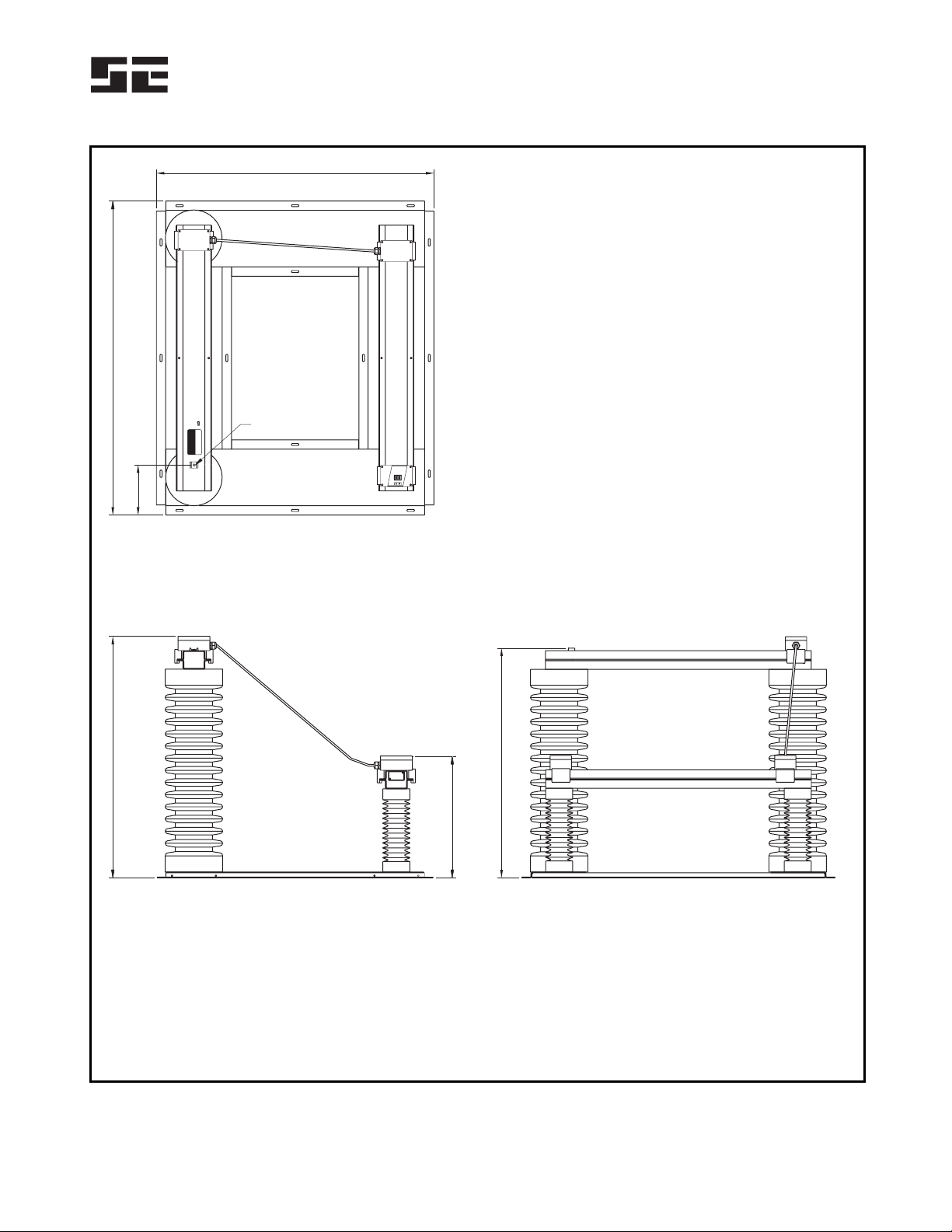
Pub. SE-330HV-M, March 24, 2006.
RIGHT SIDE
863.6
(34.00)
FRONT
TOP
457.0
(17.99)
908.0
(35.75)
1044.9
(41.14)
1181.1
(46.50)
188.6
(7.42)
TERMINAL N
0.25-20 BINDING
HEAD
NOTES:
1. DIMENSIONS IN MILLIMETRES (INCHES).
2. TERMINAL-BLOCK SCREWS: 6-32 x 0.25.
3. MOUNTING SCREWS: M6 OR 0.25-20.
4. USE LIQUID-TIGHT GLAND FOR
TERMINAL-BLOCK-ENCLOSURE CABLE ENTRY.
RATINGS:
MAXIMUM VOLTAGE . 44,000 Vac
MAXIMUM CURRENT. 220 mA
RESISTANCE .......200k
THERMAL ..........1MINUTE ON
120 MINUTES OFF
W
N
VOLTAGEAT TERMINAL N RISES
TOLINE-TO-NEUTRAL VOLTAGE
WHENA GROUND FAULT OCCURS
CAUTION
HIGH VOLTAGE
STARTCO
ENGINEERINGLTD.
MADEIN SASKATOON, CANADA
ER-72KV
SENSINGRESISTOR
200K
44,000VAC MAX
1MINUTEMAX
W
FIGURE 9. ER-72KV Sensing Resistor Outline.

Startco Engineering Ltd. Page 13
SE-330HV Neutral-Grounding-Resistor Monitor Rev. 0
Pub. SE-330HV-M, March 24, 2006.
355.5
(14.00)
247.7
(9.75)
514.4
(20.25)
1009.7
(39.75)
247.7
(9.75)
768.4
(30.25)
775.0
(30.50)
2286.0
(90.00)
MINIMUM
DISTANCE
TO ADJACENT
OBJECTS
MINIMUM VERTICAL
CLEARANCE: 1800.0 (70.87)
247.7
(9.75)
650.7
(25.63)
1146.0
(45.13)
365.0
(14.38)
247.7
(9.75)
73.0
(2.88)
432.0
(17.00)
2133.6
(84.00)
432.0
(17.00)
432.0
(17.00)
432.0
(17.00)
140.0
(5.50)
NOTES:
1. DIMENSIONS IN MILLIMETRES (INCHES).
2. MOUNTING SCREWS: M6 OR 0.25-20.
ER-72KV ORIENTED
WITH TERMINAL N
IN THIS LOCATION
FIGURE 10. ER-72KV Sensing Resistor Mounting Details.
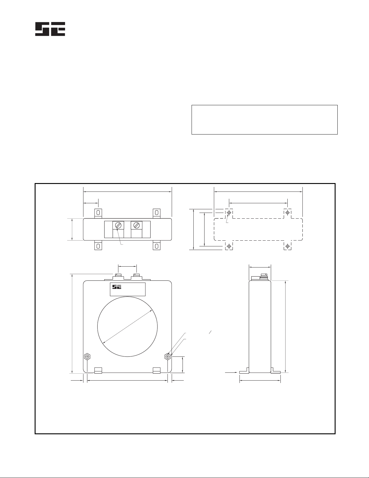
Startco Engineering Ltd. Page 14
SE-330HV Neutral-Grounding-Resistor Monitor Rev. 0
Pub. SE-330HV-M, March 24, 2006.
3.3 GROUND-FAULT CT
Select and install a ground-fault CT that will provide
the desired trip level. Typically, the CT-primary rating
should approximately equal the NGR let-through-current
rating. This provides an appropriate GF TRIP LEVEL
setting range and analog-output scaling. See
Sections 2.1.2 and 2.8.
Outline and mounting details for the sensitive
EFCT- and SE-CS30-series current sensors are shown in
Figs. 11, 12, and 13. Ground-fault-CT connections and
the preferred ground-fault-CT location are shown in
Fig. 3. If a ground fault in the NGR is unlikely, a
minimal loss of protection will result if the ground-fault
CT monitors the NGR connection to ground rather than
its connection to neutral. A minimal loss of protection
will also result if the sensing-resistor-to-neutral
connection does not pass through the CT window. This
alternate CT location is shown in Fig. 3.
The accuracy of a typical current transformer
decreases below 5% of its current rating. CT-primary
current injection testing is recommended to verify trip
levels below 5% of the CT-primary rating. See
Section 9.4. Startco sensitive current sensors are
designed for use at low levels and respond linearly to 2%
current.
NOTE:The current-transformer insulation class is of no
consequence if its secondary is grounded and the
conductors through its window are insulated for the
system voltage.
121.0
25.0
110.05.5 5.5
22.0
82.0
56.0
121.0
80.0
30.0
20.5
30.0
138.0 MAX
126.0
56.0
46.0
(4.76)
(0.98)
(4.33)(0.22) (0.22)
(0.87)
(3.23)
(2.21)
(4.76)
(3.15)
(1.18)
(0.81)
(1.18)
(5.43)
(4.96)
(2.21)
(1.81)
M5 SCREWS
TOP MOUNTING DETAIL
NOTE 2
FRONT SIDE
5.0 (0.20) 0
NOTE 3
RECESSED FOR
8-mm HEX NUT
1.0 (0.04) DEEP
EFCT-1 EARTH FAULT CT
600 V INSULATION CLASS
STARTCO
ENGINEERING LTD.
P
P
SS
2
2
1
1
NOTES:
1. DIMENSIONS IN MILLIMETRES (INCHES).
2. MOUNTING SCREWS: M4 OR 8-32.
3. PRESS MOUNTING FEET IN PLACE USING
INSTALLATION TOOL PROVIDED.
FIGURE 11. EFCT-1 Sensitive Ground-Fault Current Sensor.

Startco Engineering Ltd. Page 15
SE-330HV Neutral-Grounding-Resistor Monitor Rev. 0
Pub. SE-330HV-M, March 24, 2006.
121.0
25.0
110.05.5 5.5
22.0
69.8
56.0
121.0
80.0
30.0
20.5
30.0
138.0 MAX
126.0
56.0
46.0
(4.76)
(0.98)
(4.33)(0.22) (0.22)
(0.87)
(2.75)
(2.21)
(4.76)
(3.15)
(1.18)
(0.81)
(1.18)
(5.43)
(4.96)
(2.21)
(1.81)
M5 SCREWS
TOP MOUNTING DETAIL
NOTE 3
FRONT SIDE
Ø 5.0 (0.20)
RECESSED FOR
8-mm HEX NUT
1.0 (0.04) DEEP
P
P
SS
2
2
1
1
STARTCO
ENGINEERING LTD.
SE-CS30-70
CURRENT SENSOR
DETAIL ‘A’
MOUNTING FOOT
INSTALLATION
TOOL
NOTES:
1.
2.
3.
DIMENSIONS IN MILLIMETRES (INCHES).
PRESS MOUNTING FEET IN PLACE USING
INSTALLATION TOOL PROVIDED (DETAIL ‘A’)
MOUNTING SCREWS: M4 OR 8-32.
FIGURE 12. SE-CS30-70 Sensitive Ground-Fault Current Sensor.
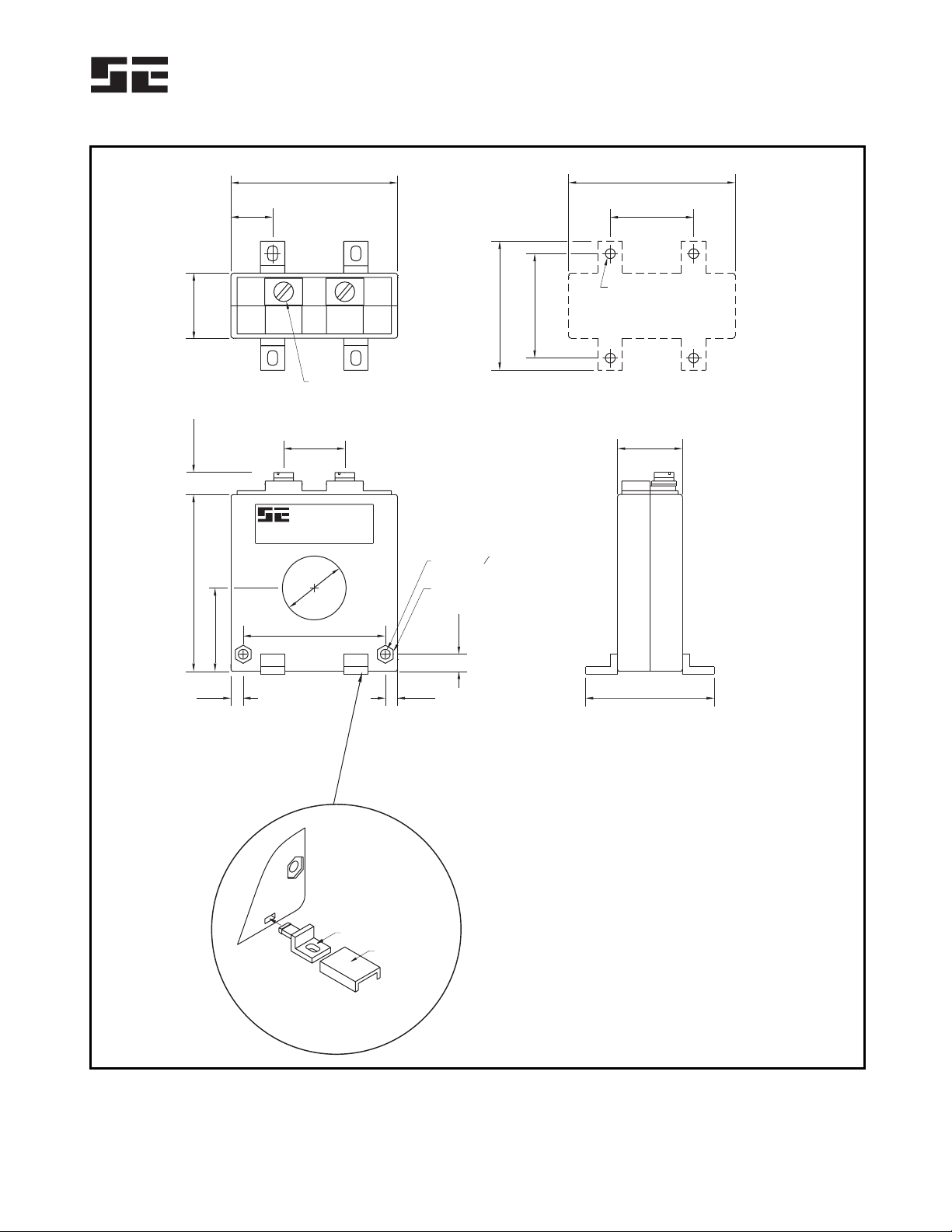
Startco Engineering Ltd. Page 16
SE-330HV Neutral-Grounding-Resistor Monitor Rev. 0
Pub. SE-330HV-M, March 24, 2006.
DETAIL ‘A’
MOUNTING FOOT
INSTALLATION
TOOL
NOTES:
1.
2.
3.
DIMENSIONS IN MILLIMETRES (INCHES).
PRESS MOUNTING FEET IN PLACE USING
INSTALLATION TOOL PROVIDED (DETAIL ‘A’)
MOUNTING SCREWS: M4 OR 8-32.
68.0
26.0
52.55.05.0
68.0
34.0
26.525.0
58.0
17.0
26.5
72.0 110.0 MAX
52.5
42.6
(2.68)
(1.02)
(2.07)(0.20)(0.20)
(2.68)
(1.34)
(1.04)(0.98)
(2.28)
(0.67)
(1.04)
(2.83) (0.43)
(2.07)
(1.68)
M5 SCREWS
TOP MOUNTING DETAIL
M4 OR 8-32 TAP
FRONT SIDE
4.0 (0.16) 0
RECESSED FOR
7-mm HEX NUT
3.0 (0.12) DEEP
P
P
SS
2
2
1
1
STARTCO
ENGINEERING LTD.
34.0
7.0
(1.34)
(0.87)
FIGURE 13. EFCT-26 and SE-CS30-26 Sensitive Ground-Fault Current Sensors.
Table of contents
Other Startco Monitor manuals


