Stealth Acoustics SA2400 MKII User manual

Front Panel
1. Power Button with indicator light
(red when powered o)
2. IR Sensor
3. Main Menu Button
4. Menu Navigation Buttons
5. Enter/Ok Button
6. Return to Previous Menu Button
7. Display Screen
8. Volume -/+ Buttons
9. Clipping Lights
10. Removable Rack Ears
Rear Panel
11. XLR Balanced Line Output
12. RCA Unbalanced Line Level Output
13. RCA Unbalanced Line Level Input
14. XLR Balanced Line Input
15. Ground Lift Switch (for hum reduction use)
16. Speaker Level Input/Output Terminal Block
17. Optical Input
18. 12V Trigger (In/Out)
19. No Signal Auto-Mute Switch (default = ON)
20. USB (Type B) for Computer Connection
21. Main Power Switch
22. Channel 1 Speaker Binding Posts
23. Channel 2 Speaker Binding Posts
24. Voltage Indicator
25. 115V-230V 50Hz / 60Hz AC Inlet
(Auto Voltage Select)
10 11 12 13 14 15 16 17 18 19 20 21
22 23 24 25
IMPORTANT SAFETY PRECAUTIONS:
Read these instructions and keep this guide for future reference.
Do not block ventilation openings.
Do not install near any heat sources such as radiating heat registers, or other apparatuses that produce heat.
Do not expose this equipment to rain or moisture.
Do not defeat the safety purposes of the polarization or grounding type plug.
Ensure proper AC mains power cord is connected.
Clean only with a soft dry cloth.
Refer all repairs to a qualified service professional.
2 973 4 5 6 8 101

QUICK START
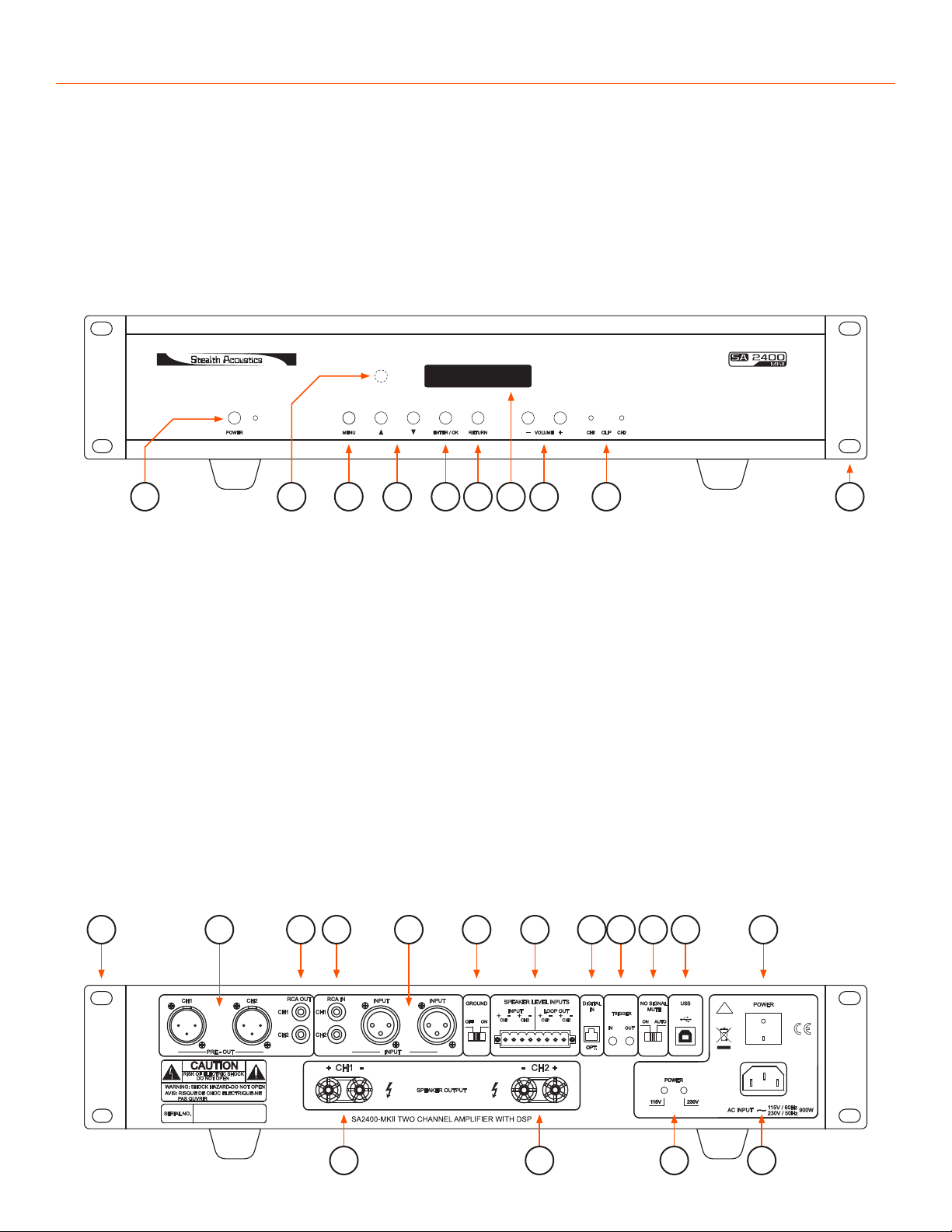
Connect audio source to amplifier
using appropriate input jacks.
Connect speakers to speaker output
binding posts noting proper polarity.
Connect appropriate AC power cord to AC inlet
and to AC mains source (115v-230v 50Hz / 60Hz).
Turn on sound source to normal level.
Turn on SA2400 amplifier. (Volume will fade in
to factory default level of 40 dB or last setting.)
Adjust volume using front panel controls.
Program DSP features using the front panel
controls. (See Front Panel Programming
section in this document.)
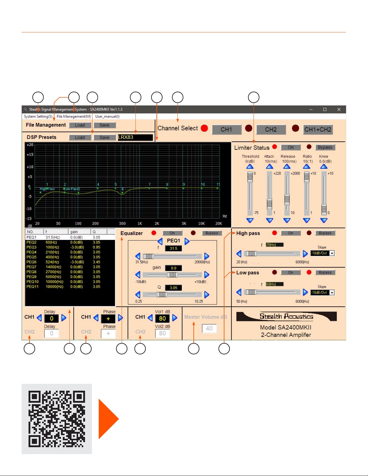
Download Stealth Signal Management
System (SSMS) software for free from
StealthAcoustics.com for additional interfacing
capabilities. A Windows™ based computer must
be connected via USB to use this feature.
OVERVIEW
The SA2400 amplifier is a reliable high-current power
source for Stealth speakers and subwoofers, as well as
for powering any traditional loudspeaker. The SA2400
features fully-independent channel programming for
maximum flexibility and incorporates powerful internal
Digital Signal Processing (DSP) which may be configured
using the front panel buttons, or by using the Stealth
Signal Management System (SSMS) software on a USB
connected Windows™ based computer.
SA2400MKII FEATURES
12V Trigger Function
450W per Channel (@ 4Ω)
Programmable Channel Assignment of
Inputs (including mono-summing)
Variable High Pass and Low Pass Filters with
Filter Slope Selections (per channel)
Eleven Bands of Fully-Parametric EQ (per channel)
Full Limiter Stage with Variable Threshold,
Attack, Release, Ratio and Knee (per channel)
Delay (100 milliseconds maximum) (per channel)
Internal Pink Noise Generator
Ten Savable and IR Recallable
Internal Amplifier Presets
Stealth Factory Optimization Presets
for Quick and Repeatable Tuning of
Stealth Speakers and Subwoofers
Full File Management via Optional Free SSMS
software for Storing Unlimited Configurations
IR Control of Volume and Preset Selection
Input Pass Through Selectable
Either “Pre” or “Post “ DSP
INTERNAL PRESETS
Presets store and recall a complete DSP state of the
amplifier (other than routing, utility and master volume
settings) and are a quick way to setup a Stealth speaker
system, or change usage modes (EG: day mode / night
mode, etc.). Presets may be recalled via IR command;
from the front panel menu; or via Stealth’s SSMS
software. (See Software Programming section in this
document.)
The SA2400MKII has 10 internal amplifier DSP presets:
Presets are used to recall and
store speaker optimizations,
EQ, individual channel levels, or
other amplifier DSP settings.
The internal amplifier Presets
are pre-loaded with factory
optimization parameters for Stealth
speakers and subwoofers.
Presets may be reconfigured and saved
via the front panel buttons, or for more
versatility, by using SSMS software
and a USB connected computer.
Additional custom or factory preset
configurations and unlimited amplifier
DSP configurations may be stored and
recalled using Stealth SSMS software
and a USB connected computer.
Preset 1 LR6G optimization (stereo)
Preset 2 LR8G optimization (stereo)
Preset 3 LR3G optimization (stereo)
Preset 4 LRX-85-ACT optimization (bi-amp)
Channel 1 Low Frequency
Channel 2 High Frequency
Preset 5 LRX-83 optimization (stereo)
Preset 6 StingRay 6 optimization (stereo)
Preset 7 StingRay 8 optimization (stereo)
Preset 8 B22G | B30G | StingRay 430 | Image Sub (subwoofer)
Channel 1 & 2 configured for subwoofer use
Preset 9 LRX-85 optimization (stereo)
Preset 10 Full Range + Subwoofer optimization (bi-amp)
Channel 1 Low Frequency - SR430
Channel 2 High Frequency - StingRay 6

FRONT PANEL PROGRAMMING
While using SSMS software programming is preferred for quickly adjusting the DSP functions, you may also perform
all DSP programming from the front panel buttons as well as adjust other parameters like input routing, pre/post DSP
pass through settings, input defaults and front panel display brightness. Please refer to the front panel diagram for the
location of the following Menu and Menu Navigation buttons:
Main Menu Button - Accesses the front panel menu structure; select individual channel, or both channels together
for programming.
Menu Navigation Buttons - Steps through the available menu items.
Enter/Ok Button - Selects the displayed menu item.
Return to Previous Menu Button - Reverts to the previous Menu item. Multiple presses exits the menu, returning the
display back to normal operation.
Below are non-DSP programming features of the SA2400. These and certain other functions are accomplished only
from the front panel buttons. See the Programming Menu - Front Panel Navigation diagram in this document for
complete menu programming options.
Setup Menu - Input Assign
Input routing and other non-DSP “Utility” functions are accomplished via the front panel menu buttons under the
Setup/Input Assign menu (see Programming Menu - Front Panel Navigation diagram). You may assign any physical
input channel to either or both amplifier channels. This allows for functions such as “mono-summing” of the stereo
inputs into two mono signals, or to map inputs to dierent outputs. Default assignment is: Chnl1=Chnl1; Chnl2=Chnl2.
Pass Through Output Assign
Selects whether the line level pass-through outputs are tapped before or after the DSP stage. When in “Pre-DSP”
(default) mode, the pass through outputs are unaected by DSP programming. In “Post-DSP”, any DSP programming
of input signals is sent to the line-level output jacks. Default setting is “Pre-DSP”.
DSP Presets
10 internal DSP presets may be recalled and saved using the front panel buttons, or via IR commands. Factory settings
for optimizing Stealth speakers are pre-installed in the presets, which may be altered, renamed and re-saved depending
on need. See Internal Presets section for more details on DSP presets.
Display Brightness
The front panel LCD display brightness is adjustable as “Bright” or four levels of “Dim” to suit the installation needs.
Utility Functions
A built in Pink Noise Generator is available under the Utility menu, as well as firmware version information and factory
default settings.
Auto Input Sensing
The amplifier may be set to automatically detect an Optical or Analog input, or to amplify only the Analog, or Digital
Optical inputs. Default = Auto (amplifier auto detects optical signal presence).
IR CONTROL
Master Volume and Internal Preset recall my be remotely controlled via IR commands, using the front panel IR target
and an IR compatible remote control or control system.
IR HEX command strings are available at StealthAcoustics.com/sa2400-mkii

EQ
Pass Filters
Setup
Input
EQ Band
EQ Switch
LPF Switch
HPF Switch
HPF/LPF
Phase
Brightness (LCD)
Utility
Auto
Analog
Opt. (optical)
Ch-1
Ch-1+2
Ch-2
Menu
Pink Noise
Factory Default
Test
Version
Band (1-11)
EQ Bypass
EQ On
Noise Level
Noise 1 Switch
Noise Gain __
On
Bypass
Noise 2 Switch
On
Bypass
Volume Max = __bB
Bright / Dim (0-3)
Ratio
Thresh
Release
Knee
Attack
Limiter Ratio = __
Limiter Thresh = __dB
Limiter Release = __ms
Limiter Softknee = __dB
Limiter Attack = __ms
Save
Load
Phase Reverse
Phase Normal
LPF
HPF
Limiter Switch
Limiter Bypass
Limiter On
Delay Delay __ ms
Pass-Through Out
Post-DSP
Pre-DSP (default)
Auto Standby
O (default)
On
Reset
SA2400 (ver.xx.hex)
HPF Bypass
HPF On
LPF Bypass
LPF On
Freq = __Hz
Slope = __dB
Slope = __dB
Freq = __Hz
Q = __
G =__dB
F =__Hz
Chnl 1+2
Chnl 2 (default)
Chnl 1
Chnl 1+2
Chnl 2
Chnl 1 (default)
Presets (1-10)
Chnl 1
Chnl 1+2
Chnl 2
Input Assign
Volume Max
Limiter
DSP Presets
PROGRAMMING MENU - FRONT PANEL NAVIGATION

STEALTH SIGNAL MANAGEMENT SYSTEM (SSMS) SOFTWARE
Programming of the amplifiers DSP section is best accomplished via a graphical user interface, using Stealth’s free
Stealth Signal Management System software (SSMS) and a USB connected Windows™ computer. The software allows
the programmer to easily see and manipulate DSP programming for either channel independently, or both channels
together, all from one screen.
The SA2400MKII requires SSMS Version 1.0.7 or later
8 9 10 1211 13
1 3 4 5 762
14
Download the Stealth Signal Management System
software for powerful DSP programming tools.
StealthAcoustics.com/sa2400-mkii

1. System Settings menu: Access Pink Noise Generator and other factory settings
2. File Management Menu and Buttons: Recall and Save complete DSP setting files
3. DSP Presets Buttons: Load or Save a DSP state via one of the 10 internal amplifier Presets
4. Preset Name Window: Presets can be named when saving in software
5. Resultant Graph Display: Indicates current settings of EQ and Pass Filters when EQ and Filters are turned on.
6. Channel Select Buttons: Program either CH1, CH2 independently, or CH1+CH2 together
7. Limiter Stage: Use for speaker protection from overload, or to set maximum
allowed output from amplifier using threshold control
8. Channel Delay: Delays a channels signal output from 0-100 Milliseconds
9. EQ Settings Window: Indicates parameter settings for all 11 Parametric EQ’s, as set by the EQ Section controls
10. Channel Phase: Toggles signal polarity on either channel
11. EQ Section: Use arrows and sliders to select and set Frequency, Gain and Filter-
width (Q) parameters on each of the 11 per-channel EQ bands
12. Channel Volume / Balance: Controls individual channel volume levels
13. Master Volume: Adjusts master output volume of both channels. Mirrors front panel Volume Control Buttons
14. High and Low Pass Filters: Use to set frequency and select slope of Pass
Filters (for bi-amplification, LF/HF roll-o, or subwoofer use)
SLEEP SETTING (when 12V trigger is not used)
By default, the amplifier is designed to go into a low-power sleep setting after a period of no signal input. When signal
input is restored the amplifier will wake for use. For this sleep setting to function the No Signal Mute switch on the back
panel must be in the ON position (factory default) AND the Auto Standby setting in the menu system must be set to
OFF (factory default).
If the amplifier is not entering or exiting the sleep state properly verify the two settings above are configured to
their factory default states as noted.
12V TRIGGER - NO SIGNAL MUTE
Convenient 12V 1/8” mini TS input and output trigger jacks on the amplifiers rear panel connect to other 12V compatible
components (tip = +12V / sleeve = ground). When +12V is present at the tip of the input jack, the amplifier will become
active. When the amplifier is active +12V is present on the tip of the output jack, which may be used to activate other
12V trigger-compatible components.
Alternately, the amplifier may be set to a “No Signal Auto-Mute” function via the rear panel switch, which turns the
main amplifier o after a few minutes if no signal is present at the inputs. When in the “Auto” position, the amplifier will
immediately come to life in response to any input signal. When the switch is set to “On”, the amplifier remains active,
even if no signal is present.
12V TRIGGER INITIATION
In some installations utilizing the amplifiers 12V trigger input, a one-time initiation procedure may be required.
Before performing this procedure, ensure that you have a properly configured switched 12V source connected to the
amplifier. Some devices provide voltages other than 12V and other devices require the trigger voltage output to be
turned on or configured. Please consult the documentation for your trigger source device.
Use the included MONO 1/8” mini TS cable for 12v trigger connections. A STEREO 1/8” mini TRS cable will not work.
It is always a good practice to use a volt meter to verify proper voltage and switching at the plug connected to the
amplifiers 12V jack.
If the amplifier does not immediately respond to a 12V trigger voltage connected to the amplifier, please take the
following actions:
1. Turn the amplifier on by pressing the front panel power button. Wait until the
front panel display shows SA-2400 MKII after the volume ramps up.
2. Apply a standard 12V trigger voltage to the “Trigger In” jack on the rear panel of the amplifier.
3. Remove the 12V trigger voltage by turning o the source of the 12 volt feed.
4. Re-activate the 12V volt trigger. This will turn the amplifier on.
5. From this point the amplifier will respond to the 12V trigger state.
Note: When the amplifier is turned o with 12V triggering, the red light on the front of the unit will light up when the
amplifier is o.

SPECIFICATIONS*
Power Output (per channel – both channels driven)
310 watts @ 8Ω< 0.05 THD
450 watts @ 4Ω< 0.05 THD
Frequency Response
20Hz-50kHz (+1/-3dB)
Total Harmonic Distortion
< 0.05 @ 460 watt @4Ω/ 1 kHz
Signal to Noise Ratio
>105 dB / A weighting 20Hz-20kHz
Analog Input Sensitivity
-1dBV for output of 312.5W / 8Ω
Maximum Voltage Gain
36 dB / 8Ω
Crosstalk
>85dB
System Impedance
8ΩNominal – 4ΩMinimum
Maximum Full Output Current Draw
1080 watts @115V / 8Ω
(100Hz sine wave – both channels driven)
1560 watts @115V / 4Ω
(100Hz sine wave – both channels driven)
Average Output Current Draw
1/8 Audio Power = 135W (1.17A) average @ 115V / 8Ω
(normal audio program)
1/4 Audio Power = 270W (2.34A) average @ 115V / 8Ω
(heavy bass program / subwoofers)
1/8 Audio Power = 195W (1.69A) average @ 115V / 4Ω
(normal audio program)
1/4 Audio Power = 390W (3.39A) average @ 115V / 4Ω
(heavy bass program / subwoofers)
Heat Dissipation
849 BTU/Hr
Amplifier / Load Protection
Full short circuit, open circuit, thermal,
ultrasonic and RF protection
On/O muting with auto volume
ramp up on power-up
DC fault power supply shutdown
Fixed high-pass filter @18Hz
Stable into reactive or mismatched loads
Dimensions
Width: 19” (483 mm) (rack ears installed)
Width: 17” (432 mm) (rack ears removed)
Height: 3.5” (89 mm)
Depth: 15.75” (400 mm)
Rack Mountable
(2) RU spaces: 3-1/2” (89mm)
Removable rack ears
Shipping Weight
38 lbs. (17.2 kg)
*All specifications subject to change.
StealthAcoustics.com
T 888.865.6800 | F 360.424.8872
A Division of Dimensional Communications, Inc.
1220 Anderson Road | Mount Vernon, WA 98274
©2021 Stealth Acoustics REV 21.04
For technical support
contact your local dealer or:
Email: Stealth@StealthAcoustics.com
Tel: +1 360 848 6800
Table of contents
Other Stealth Acoustics Amplifier manuals