Steco ARTA series Instruction manual

REV.01 / 2012 122088

2
CAUTION!
Observe the safety instructions of this
installation and maintenance manual
before placing the boiler in operation.
If an unqualified person carries out
installation, adjustment, modification,
operation or maintenance of the heating
system, this may result in danger to life
and limb or property damage. The
directions of this installation and
maintenance manual must be followed
precisely. If you require assistance or
further information, contact a qualified
installer or an appropriate service
provider.
The installation and service instructions
are a component of the technical
documentation and must be handed over
to the operator of the heating system.
Discuss the instruction in this manual
with the owner or operator of the heating
system to ensure that they are familiar
with all information required for operation
of the heating system.

3
Contents
Information on the boilerplate 4
Boiler dimensions 5
Boiler packaging 6
Technical parameters 7
Introduction 8
Ensuring safety of equipment and people 9
Operating instructions 9
ARTA series boiler general features 9
Recommended fuel 9
Control and safety devices 10
Thermo-mechanical regulator 10
Regulating hatch 11
Air rosette 11
Thermometer 11
Putting the boiler into service 11
Checking the boiler before turning it on 11
Filling and draining the heating system 11
Operation and controls 12
Starting a fire 12
Setting outlet water temperature 12
Stoking 12
Overnight heating mode 13
Removing solid combustion residuals 13
Dewing and tarring 13
Boiler shutdown 13
Short-term shutdown 13
Long-term shutdown 14
Important information 14
Boiler repairs 14
Warranty and warranty conditions 14
Boiler delivery 14
Installation instructions 14
Boiler installation – General information 14
Heating water requirements 15
Boiler Location 15
Minimum distance 16
Boiler room disposition layout 16
Chimneys and chimney connection
Warnings, Flue pipe installation 17
Accumulator tank capacity 19
Transportation and storage 19
Boiler cleaning 20
Flue gas cleaning 20
Ash pan cleaning 21
Hydraulic connection diagrams 22
Boiler combustion system 23
Air inlets 23
ARTA boiler parts 24
ARTA boiler spare parts lists 25
Troubleshooting 27
Notes 28

4
Information on the boilerplate
The boiler serial no is shown on the plate
which is attached to the backside cover panel
of the boiler body.
20, 26, 35, 43

5
Boiler dimensions

6
Boiler packaging

7
Technical parameters

8
Introduction
1. The boiler and all associated equipment
must be installed and used in accordance
with the installation design, all applicable
legal regulations and technical standards and
with the manufacturer’s instructions. The
boiler may be used only for the purpose for
which it is intended.
2. The boiler may be installed only in an
environment, which it is designed for. If the
same person who installs it delivers the boiler
to the client, he must give the user also all
accompanying boiler documentation (in
particular User Guide, Service Book, etc.).
Until the boiler is put into service, the original
packaging must be kept in case the boiler
has to be transported again.
3. After installation, the boiler must be
put into operation by a service organization
authorized by the manufacturer.
4. The boiler complies with regulations
applicable in the European Union. When
used in the conditions of countries outside at
EU, any deviations from local regulations
must be identified and rectified.
5. In the event of a defect call an
authorized manufacturer’s service
organization – any unauthorized interference
may damage the boiler (and possibly also
associated equipment!).
6. The service technician putting the
boiler into operation for the first time must
show the user the various parts of the boiler
and how to control the boiler, with the boiler
safety elements, their signals and appropriate
user reaction to them, with fundamental parts
of the boiler and their controls. If the same
person who installs it delivers the boiler to the
client, he must make sure that the original
packaging is available in case the boiler has
to be transported again.
7. Check the delivery for completeness.
8. Check whether the model and type supplied
is suitable for the required use.
9. Whenever you are not certain how to
control the boiler, study appropriate
instructions in this Operation and installation
Guide carefully and proceed accordingly.
10. Never remove or damage any markings
and signs on the boiler. Keep the original
packaging until the boiler has been put into
service, in case the boiler has to be
transported again.
11. When making any repairs, only original
parts must always be used. It is forbidden to
make any changes to the boiler’s internal
installation, or to interfere with it in any way.
12. At the end of its life cycle, the boiler its
package and its parts must be disposed of in a
way avoiding harm to the environment.
13. The manufacturer disclaims any
responsibility for damages caused by the
failure to abide by:
•The conditions stipulated in this Operation
and Installation Guide
•Applicable regulations and standards.
•Sound installation and operation
procedures.
•Conditions stated in the Warranty
Certificate and the Service Book.
•The conditions stipulated in this Operation
and Installation guide
Situations might occur in practice, when the
following essential precautions must be taken:
Shut the boiler down every time when here
are any (even temporary)

9
Flammable or explosive fumes present on the
premises from combustion air are supplied to
the boiler (e.g. from paint when painting,
laying and spraying molten substances, from
gas leakage, etc.).
If it is necessary to drain water from the
boiler or from the whole system, the water
must not be dangerously hot;
If there is any leakage from the boiler’s heat
exchanger, or when the exchanger is clogged
up with ice, do not attempt to start up the
boiler until normal operating conditions have
been restored;
Ensuring safety of equipment and people
The boiler (and all accessories) complies with
the requirements of EN 303 – 5 its updates
and all relevant European standards.
In order to run and operate the boiler in
accordance with the purpose for which it is
designed in actual conditions of use
(hereafter referred to only as use), it is
necessary to abide also by additional
requirements the most essential ones of
which (i.e. those which must not be omitted)
are found in the related regulatory
documents.
In addition to the above-mentioned
documents, it is necessary when using the
boiler to proceed in accordance with this
Operation and Installation guide and the
accompanying boiler manufacturer's
documentation.
Any interference by children, persons under
the influence of narcotic drugs, certified
persons, etc., when using the boiler, must be
prevented.
Operating Instructions
ARTA Series Boiler – General features
•ARTA series solid fuel fired boiler is
designed for heating both residential and
industrial buildings.
•Besides professional installation,
precondition for correct functioning of the
boiler is the required chimney thrust and
correct operation.
•ARTA series solid fuel fired boiler is
designed for heating systems, which are
suitable for forced circulation systems only.
•ARTA series boilers are available in four
output series: 20 kW up to 43 kW.
•Attached to the boiler body are sheet
metals covers are fitted on the inside with
thermal insulation.
•To ensure that the boiler functions correctly
and runs economically, it is important that
its nominal output is equal to the thermal
losses of the heated premises.
•Choosing a boiler of insufficient output will
result in inadequate heating of the
premises, and thus failure to provide a
heating comfort.
•Choosing a boiler of unnecessarily high
output will result in the boiler not running in
full output, and as a consequence in tarring
and dewing.
Recommended fuel
Recommended fuels for ARTA boilers are
coal, coke and firewood.
Optimal coal and coke granularity is 24 – 60
mm.
Optimal firewood size is logs of diameter 40 –
100 mm. Their length will depend on how
many kW size.

10
Fuel must be stored in a dry place. To reach
the boiler nominal output, water content in
firewood must not exceed 20%.
Approximate stoking intervals (referred to as
burning time) are shown in the technical data
table on page 7.
The boiler is stoked manually.
Please note
The boiler is not intended for burning any
type of waste.
Control and safety devices
Thermo - mechanical regulator
It is situated on the outlet from the boiler
body. It detects temperature of the hot water
and regulates the supply of primary
combustion air to underneath the boiler
stoker, by opening or shutting a flap situated
in the ashtray door.
Fig. 01
1. Regulation Head
2. Arm holder
3. Arm
4. Regulator body
5. Hexagon
6. Pit
When fitting the safety and the control
elements remember to meet the principles of
work safety.
If replacing of safety device and of thermo
mechanical regulator is necessary, please use
recommended devices in case of using any
other type of the device negotiate with
Honeywell.
Functionality of thermo-mechanical output
regulator must be checked or inspected bye
authorized person once in a year.
Regulating hatch
Changing the hatch position controls the
combustion intensity and thus the boiler
output. The thermo mechanical regulator is
connected with the regulating hatch by chain.
The chain is connected to the hatch in such a
way that its tension can be set.
Fig. 02
Keep objects away from regulation hatch's
front and channels for allowing primary air
transfer.

11
Air rosette
Supply of secondary combustion air is
controlled by an air rosette situated in the
boiler’s stoking door, which has a direct effect
on the level of emission.
Fig. 03
Thermometer
Hot water temperature can be checked on a
thermometer, which is situated in the upper
side boiler cover.
Fig. 04
Putting the boiler into service
Checking the boiler before turning it on
Before putting the boiler into operation, the
service technician must check:
Whether the installation conforms to the
design.
Whether the boiler has been filled in and is
under pressure (on the thermometer), and
whether there are any leakage in the heating
system;
Connection to the chimney - connection must
be approved by an authorised chimney sweep
(chimney inspection);
Functioning of the heating controls.
Please note
The service technician must show the user
how to control the boiler and enter the date
when the boiler was put into service into the
warranty certificate.
Filling up and draining the heating system
The system can only been filled up or topped
up with water which meets the parameters
specified by EN standards. The water must be
clear, colourless, free of suspended particles,
oil and chemically corrosive substances, and
must not be acidic ( PH factor must be
greater than 7.2 ). First of all, the heating
system must be thoroughly flushed and all dirt
washed out.
Please note
Water in system must not be reduced or put
out unless the boiler is in service or under
freezing danger. Against freezing anti-freeze
liquid can be added in to system water at the
rate of % 15.
Please note
The failure to meet this requirement may lead
to the heat exchanger getting clogged up, and
the steel block may crack as a result.

12
During the heating season, a constant
volume of water must be maintained inside
the heating system. When topping up water,
care must be taken that no air is sucked into
the system. Water must never be let out of
the boiler or the heating system, unless it is
absolutely essential, such as before repairs,
etc. Draining water and refilling the system
ial, such as before repairs, etc with new water
increases the risk of corrosion and formation
of incrustation.
Please note
Filling or topping up water to the heating
system must always be done with the boiler
cold or cooled down; otherwise the boiler
block may crack!
Operation and controls
Starting a fire
Check on the thermometer whether there is
enough water in the heating system. Open
the shutting valve between the boiler and the
heating system. Spread paper on top of the
clean stoker and then enough finely chopped
wood. Open the flue flap in the chimney
adapter and shut the stoking door. Light the
paper through the open ashtray door and fully
open the regulating flap in the ashtray door.
The fire has caught up enough stoke a layer
of main fuel on top of the burning firewood.
When the fire is powerful enough, stoke more
fuel right up to the bottom edge of the stoking
door and level it into.
Provide an even layer throughout the entire
boiler depth. If the fuel suddenly turns into
dark red blaze, open partially the secondary
air supply rosette in the stoking door. When
the flame turns yellow, shut the secondary air
supply rosette again. When the boiler has
reached the required output, it is suitable to
partially shut the flue thrust flap to prevent
heat from unnecessarily escaping into the
chimney.
•Do not start the boiler without connecting
the boiler to the chimney.
•Control chimney connections before
starting the boiler.
•Adjust the chimney blow as requested level.
If chimney blow is under mentioned levels
try not to use the boiler.
Setting the outlet water temperature
When the required outlet water temperature is
say 60 °C, heat up the boiler to a temperature
for instance 5 °C higher than the required
temperature of 60 °C (measured on the
thermometer on the boiler outlet pipe). Then
turn the control knob to 65 °C and check
whether the chain is stretched and the
regulating hatch completely shut. This position
of the chain and regulating hatch is fine-
adjusted y turning the control knob. Then let
the regulation process work. When the water
temperature drops, the regulating hatch will
start opening by the tension applied by the
regulator on the chain. When the water
temperature suddenly rises, the regulating
hatch will start opening. And the hot water
temperature on the boiler outlet is controlled.
Stoking
First shut the regulating hatch; this will shut
supply of combustion air into the boiler. Then
open the chimney flap completely. Partially
open the stoking door and wait until all
combustion gases have been sucked from
the combustion chamber into the chimney.

13
Only then open the stoking door completely
and start stoking the boiler. After shutting the
stoking door, set the chimney flap again and
restore the functioning of the regulating
hatch.
•Boiler doors must not be held open as the
boiler is continuously working.
•Provide a minimum 5 cm gap to be
between top point of the fuel and ceiling of
stoking chamber when boiler is stoked.
Overnight heating mode
This mode is used when you want to maintain
the fire in the boiler for instance over night.
First scrape all ash out of the combustion
chamber, with the chimney flap completely
opened. Then stoke the boiler with fuel and
shut the boiler up completely. Then shut the
chimney flap and also almost shut the
regulating hatch. This will reduce the chimney
thrust and restrict the supply of combustion
air. Shut also the secondary air supply
rosette in the stoking door. To restore the
boiler’s required output, just open the
chimney flap and partially open the regulating
hatch to the required boiler output.
Removing solid combustion residuals
Removing and emptying the ashtray situated
underneath the stoker in the ash
compartment do this. This must be done on a
regular basis to prevent ash from
accumulating and blocking the supply of air to
the combustion chamber from underneath the
stoker.
Dewing and tarring
When starting fire in a cold boiler, water
condensates on the walls and runs down into
the ash compartment, which may make an
impression that the boiler is leaking. This
dewing will disappear after the astray has
settled on the boilers inside walls. When
running the boiler with low water temperature
usually below 65 °C, or when using damp fuel,
water condensates in combustion gases and
the condensate runs down the boiler’s cold
walls. Low temperature heating also reduces
the chimney life. Therefore it is recommended
to equip the boiler with for instance a four-way
blending valve which will ensure that the
temperature of return water does not drop
below 50°C. Boiler tarring occurs under similar
conditions (back of combustion air, the boiler
is choking). To prevent dewing and tarring, we
recommend you run the boiler at temperatures
higher than 65 °C and choose a boiler to
match the required heating system output. An
oversized boiler suffers unnecessarily,
because it has to be run at low temperatures.
Boiler shutdown
We do not recommend that you try to speed
up the boiler combustion process. The fuel
must burn completely on its own on the stoker.
Short term shutdown
After shutting the boiler down, clean it, remove
all combustion residuals, empty the ashtray,
clean the stoking door contact surfaces and
the ash compartment, and then shut the
boiler’s stoking door and ash compartment
door.

14
Long term shutdown
When shutting the boiler down for a
protracted period of time (heating season
end), the boiler must be thoroughly cleaned
from all soot and ash sediments, in which
dampness accumulates and causes
excessive corrosion of the boiler body.
Important information
•An adult person familiar with these
operating Instructions may only operate
the boiler.
•Shut the boiler down every time there are
any (even temporary) flammable or
explosive fumes present on the premises
from which combustion air is supplied to
the boiler (e.g. From paint when painting,
laying and spraying molten substances,
from gas leakage, etc.).
•It is forbidden to light the boiler with
explosive substances.
•It is forbidden to overheat the boiler.
•At the end of the heating season the boiler,
flue and flue adapter, must be thoroughly
cleaned. Lubricate all hinges, the flue flap
mechanism and other moving.
Boiler repairs
An authorised service technician or
organisation may repair the boiler only. The
user or owner may do only normal
maintenance and simple replacements of
some parts–e.g. sealing cords.
Please note
When repairing the boiler, original parts must
always be used.
Warranty and warranty conditions
ARTA boilers are covered by warranty
specified in the warranty certificate, Service
book and user and Installation guide (chapter
Introduction, Installing the boiler).
Boiler delivery
ARTA series boilers are supplied completely
assembled and functionally tested.
The delivery includes:
1. Boiler
2. Operating and Installation Instructions
3. Service Book
4. List of service centres
5. Warranty Certificate
6. Thermo-mechanical output regulator
7. Cleaning brush
Installation Instructions
Boiler installations – General information
ARTA boilers must be put into service by an
authorised service. A network of authorised
service organisations, which meet these
conditions, is available for all boiler
installations, putting them into service and for
warranty repairs. These networks are
organised by STECO’s agreed distributors
outside of Turkey.
The boiler is designed to supply heating
systems with gauge pressure up to 400 kPa
which use water that meets the
requirements of related standards (under
no circumstances may the water be acidic, i.e.
it must have pH>7, and it should have
minimum carbon hardness).

15
The heating system must be designed in
such a way that hot water can circulate all the
time through at least some of the radiators.
Antifreeze fluids – because of their unsuitable
properties, we do not recommend to use
them. They have a reduced ability to transfer
heat, have large volumetric expansion, age
and damage rubber components. If under
concrete circumstances there is no other
option how to reliable prevent.
Before final installation, the heating system
distribution piping must be flushed several
times with pressurised water. In old, already
used system, the flushing must be done in
opposite direction to the hot water circulation.
In new systems, all radiators must be cleaned
from conservation material. And rinsed with
warm water under pressure.
We recommend installing a sludge trap
upstream of the boiler (i.e. on hot water
return pipe). The sludge trap design should
allow emptying in regular intervals, without
the need to drain a lot of hot water. The
sludge trap may be combined with a filter;
however, a filter alone will not provide an
adequate protection.
Please note
•System must be connected to open
expansion tank for safety reasons.
•Any valve must not be connected to safety
input and safety output lines.
•For increasing safety of the system, by-
pass line must be installed on the line
between input and output of circulation
pumps, as shown in diagrams.
•By-Pass line's valve must be kept closed
as the boiler is working normally.
•By-Pass line's valve can be used in
electricity problems and must be opened if
there is a risk of overheating in system
water caused by an electricity cut or
problem.
•The pipe used in by-pass line must be at
least in the diameter of plumbing systems
pipe.
•UPS (Power Supply Units) can be used for
preventing electricity problems.
•Any problems (malfunctions) caused by
boiler clogging with dirt from the heating
system and/or malfunctions induced by
clogging, are not covered by the boiler
warranty.
•The filter as well as the sludge trap must be
checked and cleaned regularly.
Heating water requirements
Heating water requirements are specified in
EN Standards. When the sum of
concentrations of calcium and magnesium in
the water exceeds 1,8 mmol/L, additional
non - chemical treatments preventing lime
deposition must be considered (e.g. Magnetic
or electrostatic field treatment).
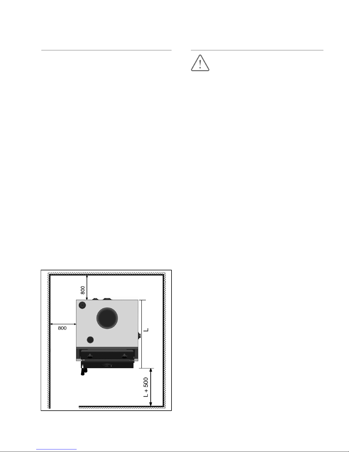
Boiler location
ARTA boilers can be located both on non-
habitable premises (e.g. in boiler room, cellar,
corridor…) and in habitable rooms. The room
in which the boiler is located must have a
permanent supply of air necessary for the
combustion process. The air must be free of
halogen hydrocarbons and corrosive vapours,
and must not be excessively humid and dusty.
The room must be protected against frost, with
ambient temperature within the range +5 °C
to +35 °C and relative humidity not exceeding
% 80.
To comply with fire regulations, the boiler must
be installed:
•On floor constructed of non-flammable
material.

16
•On a non-flammable material overlapping
the boiler footprint by 20 mm on each side
and covering the entire depth of the boiler
body.
•If the boiler is installed in a cellar, we
recommend putting it on a socket at least
50 mm high, positioning the boiler in the
middle.
To comply with standards, at least 600 mm
manipulation space must be left in front of the
boiler. Minimum distance between the back
of the boiler and the wall must be also 600
mm, and a free space of at least 600 mm
must be left between one side of the boiler
and the wall, to allow access to the rear of
the boiler. Fuel must not be stacked
directly behind on next to the boiler at a
distance less than 800 mm. If there are
two boilers in the boiler room, no fuel is
allowed to be stacked between them. We
recommend to keep a minimum distance of
800 mm between the boiler and fuel (Fig. 6),
or keep fuel in a room other than the one in
which the boiler is installed.
Minimum distance
Fig. 05
Do not put flammable materials on top of the
boiler or near the boiler than specified safety
distance.
Boiler room disposition layout
Illustrates minimum distances, which must be
kept in order to ensure safe operation of the
boiler room and allow manipulations with the
boiler, such as cleaning and stoking. The
distance between the front of the boiler and
the wall should be at least the boiler length L
plus 500 mm.
Minimum distances between the boiler side
and rear should be 800 mm with the distance
of the rear also determined by the way the
boiler is connected to the chimney.
•Feed the connector into the flue gas
system on a short, ascending path.
•Avoid deflections, especially those with an
angle of 90°.
•Fasten and support connectors
sufficiently.
•Since the flue pipe is only fixed into the
flue gas system and push-fitted onto the boiler
flue socket, it should be fitted very carefully so
that it does not come loose.
•Only use parts of non - flammable
materials for the flue gas system.

17
Fig. 06
Chimneys and chimney connection
warnings
Flue pipe installation
A sufficient flue draft of the flue gas system is
the basic requirement for the correct
functioning of the boiler.
It fundamentally affects its performance and
efficiency. Therefore, heed the following for
the flue gas connection:
•Please note that the boiler must be
connected to the flue gas system in
accordance with the relevant local.
•Building code regulations, manufacture’s
instructions and in consultation with an
approved flue installer.
•The boiler may only be connected to a flue
gas system with proper flue draft (technical
spec. table).
•The dimension calculations of the flue gas
path must be based on the flue gas mass-
flow rate at maximum rated output.
•The effective chimney flue height is
measured from the point of entry of the flue
pipe into the chimney.
•Ensure that the calculation of the flue gas
path and the connection of the flue gas
system are only carried out by qualified
personnel.
•If a wrong boiler chimney is connected, the
warranty is not valid.
Fig. 07

18
Fig. 07 shows the proper flue gas connection
with additional air equipment. Observe the
following during the installation of the flue gas
connection:
•Install a flue pipe connection with an
inspection aperture for cleaning.
•Fasten the flue gas connector piece to the
boiler.
•Feed the connector into the flue gas system
on a short, ascending path. Avoid
deflections, especially those with an angle
of 90°.
•Fasten and support connectors sufficiently.
•Since the flue pipe is only fixed into the
flue gas system and push-fitted onto the
boiler flue socket, it should be fitted very
carefully so that it does not come loose.
•Only use parts of non-flammable materials
for the flue gas system.
The figures in tab. are only guide figures. The
draft depends on the diameter, height,
roughness of the chimney wall, and the
temperature difference between combustion
products and the outside atmosphere. We
recommend the use of a chimney liner.
Have precise calculations carried out by a
heating engineer or flue installer.
Coefficient = 0,041 ( for wood )
Coefficient = 0,027 ( for carbon )
F= Sections resulting (cm2)
a = Coefficient
QN = Boiler heat output ( kCal/h )
H= Height of chimney ( meters )
Boiler Flue duct Minimum
Output size height
20 kW 150 mm 9 m
180 mm 7 m
200 mm 5 m
26 kW 150 mm 12 m
180 mm 10 m
200 mm 8 m
35 kW 150 mm 12 m
180 mm 11 m
200 mm 10 m
43 kW 180 mm 12 m
200 mm 11 m
220 mm 10 m
•Recommended minimum chimney flue
heights
•Have precise calculations carried out by a
heating engineer or flue installer.

19
Accumulator tank capacity
NOTE: The heat can be supplied for example
by an accumulator tank. The following applies
as a reference for the minimum storage boiler
content:
: Accumulator tank capacity in L
: Nominal heat output in kW
: Burning period in h
: Heating load of the premises in kW
: Minimum heat output in kW
Heating boilers using several allowable fuels
should have the tank size based on the fuel
that requires the largest accumulator tank.
The accumulator tank is not necessary when
the required volume is less than 300 l.
Transportation and storage
The manufacturer handles the boiler that is
on a palette and secured against shifting
(with screws). The boiler may not be
transported in a different position than on its
base.
At least regular storage conditions shall be
ensured during boiler storage and
transportation (non - aggressive environment,
air humidity lower than 75 %, temperature
range from 5 °C to 55 °C, low dustiness and
preventing influence of biological factors).
The force may not be applied on the boiler
coverings and panel during storage and
transportation.
Fig. 08
Fig. 09

20
Warning !
•Risk of injury from carrying heavy loads!
•Boiler must not be carried or transported
without using forklift, trans pallet or other
wheeled carrying vehicles.
•Use personal protective equipment (e.g.
helmet, safety shoes, protective gloves).
•Risk of system damage from impact
shocks!
•Fragile components could be damaged.
•Protect boiler connections from dirt if the
boiler is not to be installed immediately.
Boiler cleaning
When the boiler is used, soot and fine ash
accumulates on the boiler walls, mainly on
heat exchanger ribs and in the flue neck,
which reduces heat transfer and the boiler
output. The actual quantity of soot and fine
ash will depend on the quality of the fuel used
and on the boiler operating conditions.
If the boiler is oversized or was for some
reason run at low temperatures, more soot is
generated. This may also result in inadequate
chimney thrust.
Flue gas cleaning
The boiler must be cleaned regularly, at least
once a week, is with a steel brush.
Open the boiler upper cleaning door. All
boiler walls inside the combustion chamber
and combustion gases routes should be
cleaned.
If a larger quantity of tar has accumulated on
internal walls of the combustion chamber, it
must be removed with a scraper or burnt with
hard wood (or coke), running the boiler at
maximum operating temperature.
•Insufficient cleaning can cause damage to
the boiler and the voiding of warranty
claims.
•Risk of system damage due to insufficient
maintenance and cleaning!
Fig. 10
This manual suits for next models
1
Table of contents
Popular Boiler manuals by other brands

Baxi
Baxi Solo 3 PFL 30 Installation & servicing instructions

Baxi
Baxi Duo-tec Combi HE a Range series User operating instructions

Viessmann
Viessmann Vitodens 300 Service instructions

U.S. Boiler Company
U.S. Boiler Company K2 FT User's information manual

Lochinvar
Lochinvar Noble 100 Series Installation & service manual

Lochinvar
Lochinvar Knight XL KBN400 parts list

Laars
Laars Mighty Therm 2 200 User's information manual

Radiant
Radiant RK 55 user manual

DeDietrich
DeDietrich NeOvo Condens EFU C-S 19 FF user manual

Absolute
Absolute ABS-750 Installation and operation manual

Worcester
Worcester greenstar heatslave 18 instruction manual

M&G
M&G DuraVent DIS installation instructions