Steel Core 33015 User manual

*Actual product may vary slightly
Please carefully read and save these instructions before attempting to assemble, maintain, install, or operate this product.
Observe all safety information to protect yourself and others. Failure to observe the instructions may result in property
damage and/or personal injury. Please keep instructions for future reference.
For warranty purchases, please keep your dated proof of purchase. File or attach to the manual for safe keeping.
For Customer Service, Call 1-800-348-5004
6" 5.5 AMP CUT-OFF SAW
33015
This product can expose you to chemicals including
LEAD/CADMIUM/DEHP, which is
known to the State
of California to cause cancer and birth defects or
other reproductive harm. For more information go
to www.P65Warnings.ca.gov.
WARNING

1. KEEP GUARDS IN PLACE and in working order.
2. REMOVE ADJUSTING KEYS AND WRENCHES. Form habit of checking to see
that keys and adjusting wrenches are removed from tool before turning it on.
3. KEEP WORK AREA CLEAN. Cluttered areas and benches invite accidents.
4. DON’T USE IN DANGEROUS ENVIRONMENT. Don’t use power tools in damp or
wet locations, or expose them to rain. Keep work area well lighted.
5. KEEP CHILDREN AWAY. All visitors should be kept safe distance from work area.
6. MAKE WORKSHOP KID PROOF with padlocks, master switches, or by removing
starter keys.
7. DON’T FORCE TOOL. It will do the job better and safer at the rate for which it was
designed.
8. USE RIGHT TOOL. Don’t force tool or attachment to do a job for which it was not
designed.
9. USE PROPER EXTENSION CORD. Make
sure your extension cord is in good condition.
When using an extension cord, be sure to
use one heavy enough to carry the current
your product will draw. An undersized cord
will cause a drop in line voltage resulting in
loss of power and overheating. Table A
shows the correct size to use depending
on cord length and nameplate ampere rating. If in doubt, use the next heavier gauge.
The smaller the gauge number, the heavier the cord.
10. WEAR PROPER APPAREL. Do not wear loose clothing, neckties, rings, bracelets, or
other jewelry which may get caught in moving parts. Nonslip footwear is recommended.
Wear protective hair covering to contain long hair.
11. ALWAYS USE SAFETY GLASSES. Also use face or dust mask if cutting operation is
dusty. Everyday eyeglasses only have impact resistant lenses, they are NOT safety
glasses.
12. SECURE WORK. Use clamps or a vise to hold work when practical. It’s safer than
using your hand and it frees both hands to operate tool.
Read all safety warnings and instructions.
Failure to follow the warnings and instructions may result in electric shock, fire and/or
serious injury.
Save all warnings and instructions for future reference.
GENERAL TOOL SAFETY WARNINGS
Table A: RECOMMENDED MINIMUM WIRE GAUGE
FOR EXTENSION CORDS
(120 VOLT)
NAMEPLATE
AMPERES
(at full load)
EXTENSION CORD
LENGTH
25’ 50’ 100’ 150’
0 – 6 18 16 16 14
6.1 – 10 18 16 14 12
10.1 – 12 16 16 14 12
12.1 – 16 14 12 Do not use.

13. DON’T OVERREACH. Keep proper footing and balance at all times.
14. MAINTAIN TOOLS WITH CARE. Keep tools sharp and clean for best and safest
performance. Follow instructions for lubricating and changing accessories.
15. DISCONNECT TOOLS before servicing; when changing accessories, such as blades,
bits, cutters, and the like.
16. REDUCE THE RISK OF UNINTENTIONAL STARTING. Make sure switch is in off
position before plugging in.
17. USE RECOMMENDED ACCESSORIES.
Consult the owner’s manual for recommended
accessories. The use of improper accessories may cause risk of injury to persons.
18. NEVER STAND ON TOOL. Serious injury could occur if the tool is tipped or if the
cutting tool is unintentionally contacted.
19. CHECK DAMAGED PARTS. Before further use of the tool, a guard or other part that
is damaged should be carefully checked to determine that it will operate properly and
perform its intended function - check for alignment of moving parts, binding of moving
parts, breakage of parts, mounting, and any other conditions that may affect its operation.
A guard or other part that is damaged should be properly repaired or replaced.
20. NEVER LEAVE TOOL RUNNING UNATTENDED. TURN POWER OFF. Don’t leave
tool until it comes to a complete stop.
1. In the event of a malfunction or breakdown, grounding provides a path of least resistance
for electric current to reduce the risk of electric shock. This tool is equipped with an
electric cord having an equipment-grounding conductor and a grounding plug. The plug
must be plugged into a matching outlet that is properly installed and grounded in
accordance with all local codes and ordinances.
2. Do not modify the plug provided - if it will not fit the outlet, have the proper outlet installed
by a qualified electrician.
3. Improper connection of the equipment-grounding conductor can result in a risk of electric
shock. The conductor with insulation having an outer surface that is green with or without
yellow stripes is the equipment-grounding conductor. If repair or replacement of the electric
cord or plug is necessary, do not connect the equipment grounding conductor to a live
terminal.
4. Check with a qualified electrician or service personnel if the grounding instructions are
not completely understood, or if in doubt as to whether the tool is properly grounded.
5. Use only 3-wire extension cords that have 3-prong grounding plugs and 3-pole
receptacles that accept the tool’s plug.
TO PREVENT ELECTRIC SHOCK AND DEATH FROM INCORRECT GROUNDING WIRE
CONNECTION
READ AND FOLLOW THESE INSTRUCTIONS:
110-120 V~ Grounded Tools: Tools with Three Prong Plugs

CUT-OFF SAW SAFETY WARNINGS
6. Repair or replace damaged or worn cord
immediately.
7. This tool is intended for use on a circuit
that has an outlet that looks like the one
illustrated above in 125 V~ 3-Prong Plug
and Outlet. The tool has a grounding plug
that looks like the plug illustrated above
in 125 V~ 3-Prong Plug and Outlet.
8. The outlet must be properly installed and
grounded in accordance with all codes
and ordinances.
9. Do not use an adapter to connect
this tool to a different outlet.
For Your Own Safety Read Instruction Manual Before Operating Grinder
1. Wear eye protection.
2. Use grinding wheel suitable for speed of grinder.
3. Replace cracked wheel immediately.
4. Always use guards and eye shields.
5. Do not over tighten wheel nut.
6. Use only flanges furnished with the grinder.
7. Frequently clean grinding dust from beneath grinder.
8. Wear a full face shield over ANSI approved safety goggles during use.
9. Do not grind with side of wheel unless wheel is specifically designed for that type of
grinding.
10. DO NOT OPERATE WITH ANY GUARD DISABLED, DAMAGED, OR REMOVED.
Moving guards must move freely and close instantly.
11. The use of accessories or attachments not recommended by the manufacturer may
result in a risk of injury to persons.
12. When servicing use only identical replacement parts.
13. Only use safety equipment that has been approved by an appropriate standards
agency. Unapproved safety equipment may not provide adequate protection.
Eye protection must be ANSI-approved and breathing protection must be
NIOSH-approved for the specific hazards in the work area.
125 V~ 3-Prong Plug and Outlet
(for up to 125 V~ and up to 15 A)
Grounding
Pin

1-800-348-5004
VIBRATION SAFETY
14. Stay alert, watch what you are doing and use common sense when operating a power
tool. Do not use a power tool while you are tired or under the influence of drugs, alcohol
or medication. A moment of inattention while operating power tools may result in serious
personal injury.
15. Industrial applications must follow OSHA guidelines.
16. Maintain labels and nameplates on the tool. These carry important safety information.
17. Avoid unintentional starting. Prepare to begin work before turning on the tool.
18. People with pacemakers should consult their physician(s) before use. Electromagnetic
fields in close proximity to heart pacemaker could cause pacemaker interference or
pacemaker failure.
19. The warnings, precautions, and instructions discussed in this instruction manual cannot
cover all possible conditions and situations that may occur. It must be understood by
the operator that common sense and caution are factors which cannot be built into this
product, but must be supplied by the operator.
This tool vibrates during use. Repeated or long-term exposure to vibration may cause
temporary or permanent physical injury, particularly to the hands, arms and shoulders.
To reduce the risk of vibration-related injury:
1. Anyone using vibrating tools regularly or for an extended period should first be examined
by a doctor and then have regular medical check-ups to ensure medical problems are not
being caused or worsened from use. Pregnant women or people who have impaired blood
circulation to the hand, past hand injuries, nervous system disorders, diabetes, or Raynaud’s
Disease should not use this tool. If you feel any medical or physical symptoms related to
vibration (such as tingling, numbness, and white or blue fingers), seek medical advice as
soon as possible.
2. Do not smoke during use. Nicotine reduces the blood supply to the hands and fingers,
increasing the risk of vibration-related injury.
3. Use tools with the lowest vibration when there is a choice between different processes.
4. Include vibration-free periods each day of work.
5. Grip tool as lightly as possible (while still keeping safe control of it). Let the tool do the work.
6. To reduce vibration, maintain the tool as explained in this manual. If any abnormal vibration
occurs, stop use immediately.

SPECIFICATIONS
FUNCTIONS
1-800-348-5004
Electrical Rating 120VAC / 60Hz / 5.5A
Motor No Load Speed 5,000 RPM
Max. Accessory Diameter 6"
Arbor Size 7/8"
Handle
Trigger
Cut-Off Wheel
(not included)
Stationary
Guard
Safety Button
(on other side
of handle)
Swing
Guard
Angle
Guide
Vise
Clamp
Vise
Knob
Base
1. The Grinding Wheel MUST be:
• Rated to at least 5,000 RPM.
• No larger than 6" in diameter.
• Fitted with a 7/8" round arbor hole.
• Suitable for edge grinding, not surface grinding.
• Dry and clean.
• Proven undamaged by inspection and by the
ring-test explained below.
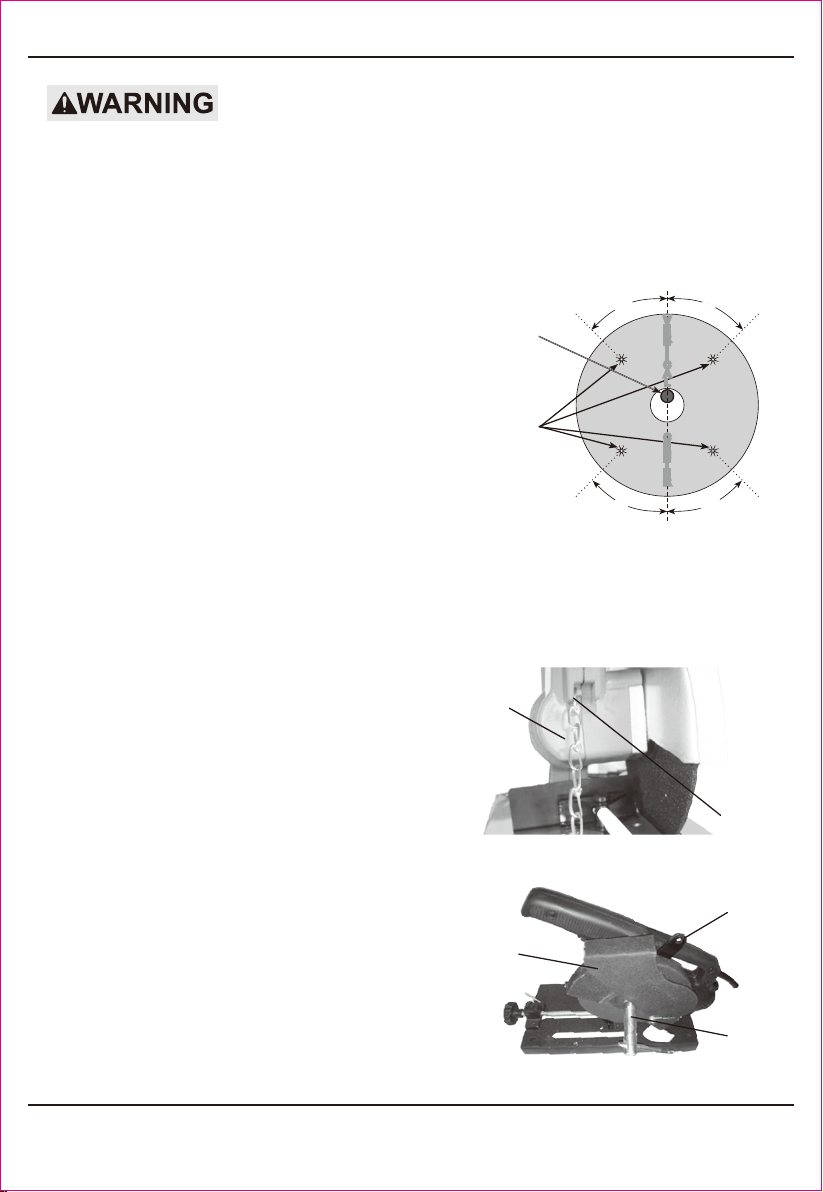
2. Closely inspect the new wheel before mounting
it. Perform a ring-test on the wheel
(unless wheel is smaller than 4″) as follows:
a. Suspend wheel using a dowel or finger through the arbor hole.
b. Tap the flat side of the wheel with a light nonmetallic object, such as a screwdriver
handle, at a point 45° from the vertical center line on each side of the wheel and
1 - 2 inches from the edge of the wheel (see Figure A).
c. Rotate the wheel 90° and repeat the test until the entire
wheel has been checked.
d. An undamaged wheel will ring with a clear tone.
If cracked, there will be a dead sound and not
a clear ring.
3. Release the Safety Chain from the securing
pin (see Figure C) and guide the Housing
to rest at its full upward position.
4. Open the Swing Guard (25) all the way,
exposing the Grinding Wheel, Outer
Flange (29) and Arbor Bolt (30).
5. As shown in Figure B, use the supplied
Flat Wrench (44) to hold the Spindle
in place and use the supplied Sleeve
Wrench (45) to loosen the Arbor Bolt.
6. Remove the Arbor Bolt, the Outer Flange
and the old Grinding Wheel, noting the
orientation of each.
1-800-348-5004
TO PREVENT SERIOUS INJURY FROM ACCIDENTAL OPERATION:
Release the pressure and unplug the tool from its electrical outlet before assembling or making
any adjustments to the tool.
TO PREVENT SERIOUS INJURY:
DO NOT OPERATE WITH ANY GUARD DISABLED, DAMAGED, OR REMOVED.
INSTALLING A CUT-OFF (GRINDING) WHEEL
Tap
Wheel
Here
45° 45°
45° 45°
Hang
Wheel
from
Dowel
V
E
R
T
I
C
A
L
C
E
N
T
E
R
Safety
Chain
Securing
Pin
Figure B: Safety Chain
Flat
Wrench
Sleeve
Wrench
Swing
Guard
Figure C: Removing the Arbor Bolt
Figure A

7. Install the new Grinding Wheel onto the Spindle. Replace the Outer Flange onto the
Spindle; thread the Arbor Bolt onto the Spindle and tighten them in place with the
Sleeve Wrench.
8. For wheels with paper gaskets (blotters) or metal gaskets: Slip the grinding wheel onto
the Arbor with the gasket first. The gasket should be centered on the grinding wheel
and the wheel and gasket should rest flat against the Inner Flange.
WARNING: To prevent serious injury, gaskets must be used for all grinding wheels they
are provided with. Gaskets help prevent grinding wheel damage and wheel slippage,
causes of wheel failure.
9. Lower the Housing and replace the Safety Chain.
1. To cut at various angles (up to 45º), adjust the
Angle Guide by loosening the two Bolts that
attach the Guide to the Base.
2. Adjust the Angle Guide to the desired setting
and then tighten both Bolts.
3. To reposition the Angle Guide for a
different sized workpiece, remove both of the
Bolts, and reattach the Angle Guide at the
other set of screw holes. See Figure D.
1-800-348-5004
ADJUSTING CUT ANGLE
1. Designate a work area that is clean and well-lit. The work area must not allow access
by children or pets to prevent distraction and injury.
2. Route the power cord along a safe route to reach the work area without creating a
tripping hazard or exposing the power cord to possible damage. The power cord must
reach the work area with enough extra length to allow free movement while working.
3.
There must not be objects, such as utility lines, nearby that will present a hazard while working.
Work Piece and Work Area Set Up
Secure loose work pieces using the Vise to prevent
movement while working: See Figure E.
1. Turn the Vise Knob counterclockwise a quarter
turn and lift up the Quick Release.
2. Slide the Vise Clamp open as far as needed.
3. Position the workpiece against the Angle Guide.
4. Push the Quick Release down onto the Vise threads.
5. Push the Vise Knob until the Vise Clamp is up
against the workpiece.
6. Tighten the Vise Knob clockwise to secure the workpiece.
USING THE VISE
Screw Holes
Angle
Guide
Bolt
Bolt
(hidden)
Figure D: Repositioning the Angle Guide
Vise
Knob
Vise
Clamp
Quick
Release
Angle
Guide
Figure E: Vise Components

GENERAL OPERATING INSTRUCTIONS
CLEANING, MAINTENANCE, AND LUBRICATION
MAINTENANCE AND SERVICING
1-800-348-5004
CAUTION! Friction from cutting will heat both the Wheel and the workpiece. Be careful
when handling the workpiece and do not overwork the Cut-Off Saw as the Wheel can
become damaged from overheating.
1. Release the Safety Chain and guide the Housing to rest at its full upward position.
2. Adjust the Angle Guide as needed.
3. Place the workpiece against the Angle Guide and clamp in place using the Vise.
4. Plug the Power Cord into a grounded, 120VAC electrical outlet.
5. Press the Safety Button, then squeeze and hold the Trigger to start the Saw. Allow
the Grinding Wheel to attain full speed.
6. With one hand on the Handle and the other hand clear, slowly bring the Saw down,
letting the Saw do the work. Do not apply excessive force.
7. After making the cut, release the Trigger and raise the Saw.
8. Wait until the Wheel comes to a complete stop, then remove the workpiece.
9. To prevent accidents, turn off the tool and disconnect its power supply after use. Lower
the Saw and secure with the Safety Chain. Clean, then store the tool indoors out of
children’s reach.
1. BEFORE EACH USE, inspect the general condition of the tool. Check for:
• Loose hardware,
• Misalignment or binding of moving parts,
• Cracked or broken parts,
• Damaged electrical wiring, and
• Any other condition that may affect its safe operation.
2. AFTER USE, wipe external surfaces of the tool with clean cloth.
3. Periodically, wear ANSI-approved safety goggles and NIOSH-approved breathing
protection and blow dust and grit out of the motor vents using dry compressed air.
4. WARNING! If the supply cord of this power tool is damaged, it must be replaced
only by a qualified service technician.
Procedures not specifically explained in this manual must
be performed only by a qualified technician.
TO PREVENT SERIOUS INJURY FROM ACCIDENTAL OPERATION:
Release the Trigger and unplug the tool from its electrical outlet before performing any
inspection, maintenance, or cleaning procedures.
TO PREVENT SERIOUS INJURY FROM TOOL FAILURE:
Do not use damaged equipment. If abnormal noise or vibration occurs, have the problem
corrected before further use.

CUT-OFF WHEEL STORAGE AND HANDLING
TROUBLESHOOTING
1-800-348-5004
1. Handle Cut-Off Wheels carefully to prevent dropping or bumping. Do not use wheels
that have been dropped or bumped.
2. Store Cut-Off Wheels in shelves, racks, boxes, or drawers. Storage area must be kept
dry, and above freezing. Any grinding or Cut-Off Wheels exposed to humidity or freezing
temperatures must not be used.
Problem Possible Causes Likely Solutions
Tool will not start. 1. Cord not connected.
2. No power at outlet.
3. Internal damage or wear. (Carbon
Brushes or switch, for example.)
1. Check that cord is plugged in.
2. Check power at outlet. If outlet is unpowered,
turn off tool and check circuit breaker.
If breaker is tripped, make sure circuit is right
capacity for tool and circuit has no other loads.
3. Have technician service tool.
Tool operates slowly. Extension cord too long or
wire size too small.
Eliminate use of extension cord.
If an extension cord is needed, use one
with the proper diameter for its length and
load. See Table A on page 3.
Performance
decreases over time.
1. Wheel worn or dull.
2. Carbon brushes worn or damaged.
1. Keep cutting accessories sharp.
Replace wheel as needed.
2. Have technician replace brushes.
Excessive noise
or rattling.
Internal damage or wear. (Carbon
Brushes or bearings, for example.)
Have technician service tool.
Overheating. 1. Forcing machine to work too fast.
2. Wheel worn or dull.
3. Blocked motor housing vents.
4. Motor being strained by long or
small diameter extension cord.
1. Allow machine to work at its own rate.
2. Keep cutting accessories sharp.
Replace wheel as needed.
3. Wear ANSI-approved safety goggles and
NIOSH-approved dust mask/respirator while
blowing dust out of motor using compressed air.
4. Eliminate use of extension cord.
If an extension cord is needed, use one with
the proper diameter for its length and load.
See Table A on page 3.
Follow all safety precautions whenever diagnosing or servicing
the tool. Disconnect power supply before service.

PARTS LIST
PARTS LIST
REF# Description QT'Y REF# Description QT'Y
1 M5 wing blot 1 36 5x14 Hexagonal screw 2
2 side cover 1 37 Ф5 spring washer 2
3 Outer Flange Nut 1 38 Terminal 2
4 Inner Flange 1 39 pin 1
5Ф5x12 s/t screw 3 40 spring 1
6Ф5 spring washer 3 41 sapport/base plate 1
7 grinder cover 1 42 Iron sheet 1
8 output shaft 1 43 machine foot 4
9 2.9x10 semi sirclekey 1 44 Gasket 4
10 4x55 Self-tapping screws 4 45 M4 nut 4
11 bearing sit 1 46 Ф4x30 s/t screw 4
12 201# bearing 1 47 chain 1
13 201# Triangle Press Cover 1 48 screw pole 1
14 Ф4 spring washer 3 49 2x20 cotter pin 1
15 Ф4x10 s/t screw 3 50 4x24 Spring pins 1
16 gear 1 51 nut holder 1
17 Ф10 retaining ring 1 52 quick nut 1
18 17# bearing 1 53 Ф6x16 s/t screw 2
19 Right Motor Housing 1 54 Ф6 spring washer 2
20 Ф4x20 s/t screw 5 55 Ф6 washer 2
21 Ф4x12 s/t screw 2 56 straight pin 1
22 switch 1 57 small clamp plate 1
23 Left Motor Housing 1 58 big clamp plate 1
24 Ф6 nut 1 59 6x14 hexagon screw 2
25 Ф6 spring washer 1 60 Ф6 spring washer 2
26 Pinion 1 61 Ф6 washer 3
27 19# bearing 1 62 cable guard 1
28 Ф3 Ball 1 63 power cord 1
29 rotor 1 64 cable press plate 1
30 brush holder 2 65 Ф4x14 s/t screw 2
31 brush 2 66 Ф20 flange 1
32 cap 2 67 Cylindrical pin wrench 1
33 18# bearing 1 68 spanner 1
34 Stator 1 69 Mobile guard 1
35 100# pull spring 2

Table of contents


