TABLE OF CONTENTS
2
Power supply 120V, 60Hz
Motor capacity 12A
Rated speed13,500 /min
Diamond cutting wheel size 5" Dia. X 5/8" or 20mm (Bore)
Maximum depth of cut at 90º 31.75mm
Maximum depth of cut at 45º23.81mm
Bevel0º and 45º
NOTICE: The manual cover illustrates the current production model. All other illustrations contained in the manual
are representative only and may not be exact depictions of the actual labeling or accessories included. They are
intended for illustrative purposes only.
TECHNICAL SPECIFICATIONS
SAVE THESE INSTRUCTIONS.
Refer to them often and use them to instruct others.
If tool is loaned to someone, also loan them these instructions.
TECHNICAL SPECIFICATIONS....................................2
GENERAL POWER TOOL SAFETY WARNINGS.........3
Safety Symbols.................................................3
Work Area Safety..............................................3
Electrical Safety................................................3
Personal Safety.................................................3
Power Tool Use and Care.................................3
Service...............................................................4
KICK BACK....................................................................5
SYMBOL DEFINITIONS.................................................5
CALIFORNIA PROPOSITION 65...................................6
SAW FEATURES............................................................6
UNPACKING..................................................................6
Shipping Contents............................................7
ASSEMBLY.....................................................................7
Attach the Blade Fence....................................7
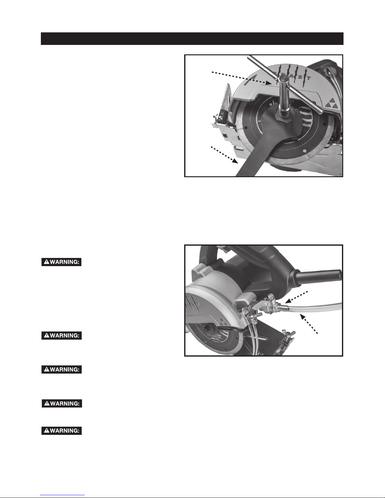
Install the Saw Blade.......................................8
Connect the Water Hose.................................8
OPERATION...................................................................9
Turning the Saw On and Off.............................9
Using the Trigger Switch Lock.........................9
Re-setting the Short-Circuit Safety Button...10
Changing the Saw Blade................................10
MAKING CUTS............................................................11
Bevel Cut.........................................................11
Adjusting Blade Height...................................11
MAINTENANCE...........................................................11
Squaring the Blade.........................................12
TROUBLESHOOTING YOUR SAW.............................13
3-YEAR LIMITED WARRANTY. ...................................13
REPLACEMENT PARTS..............................................13
Wheel peripheral gap max. 0.45 mm between segments
Wheel peripheral gap rank angle 0º
Wheel thickness 1.2 mm
2
3
Work area safety
Electrical safety
Personal safety
Power tool use and care
General Power Tool Safety Warnings
5HDGDOOVDIHW\ZDUQLQJVDQGDOOLQVWUXFWLRQV)DLOXUHWRIROORZWKHZDUQLQJVDQGLQVWUXFWLRQVPD\
UHVXOWLQHOHFWULFVKRFNðUHDQGRUVHULRXVLQMXU\
2@UD@KKV@QMHMFR@MCHMRSQTBSHNMRENQETSTQDQDEDQDMBD
7KHWHUPSRZHUWRROLQWKHZDUQLQJVUHIHUVWR\RXUPDLQVRSHUDWHGFRUGHGSRZHUWRRORUEDWWHU\RSHUDWHG
FRUGOHVVSRZHUWRRO
r*DDOVNQJ@QD@BKD@M@MCVDKKKHS&OXWWHUHGRU
GDUNDUHDVLQYLWHDFFLGHQWV
r#NMNSNODQ@SDONVDQSNNKRHMDWOKNRHUD
@SLNROGDQDRRTBG@RHMSGDOQDRDMBDNE
l@LL@AKDKHPTHCRF@RDRNQCTRS3RZHUWRROV
FUHDWHVSDUNVZKLFKPD\LJQLWHWKHGXVWRUIXPHV
r*DDOBGHKCQDM@MCAXRS@MCDQR@V@XVGHKD
NODQ@SHMF@ONVDQSNNK'LVWUDFWLRQVFDQFDXVH\RX
WRORVHFRQWURO
r/NVDQSNNKOKTFRLTRSL@SBGSGDNTSKDS-DUDQ
LNCHEXSGDOKTFHM@MXV@X#NMNSTRD@MX
@C@OSDQOKTFRVHSGD@QSGDCFQNTMCDCONVDQ
SNNKR8QPRGLðHGSOXJVDQGPDWFKLQJRXWOHWVZLOO
UHGXFHULVNRIHOHFWULFVKRFN
r UNHCANCXBNMS@BSVHSGD@QSGDCNQFQNTMCDC
RTQE@BDRRTBG@ROHODRQ@CH@SNQRQ@MFDR@MC
QDEQHFDQ@SNQR7KHUHLVDQLQFUHDVHGULVNRIHOHFWULF
VKRFNLI\RXUERG\LVHDUWKHGRUJURXQGHG
r#NMNSDWONRDONVDQSNNKRSNQ@HMNQVDS
BNMCHSHNMR:DWHUHQWHULQJDSRZHUWRROZLOO
LQFUHDVHWKHULVNRIHOHFWULFVKRFN
r#NMNS@ATRDSGDBNQC-DUDQTRDSGDBNQCENQ
B@QQXHMFOTKKHMFNQTMOKTFFHMFSGDONVDQSNNK
*DDOBNQC@V@XEQNLGD@SNHKRG@QODCFDRNQ
LNUHMFO@QSR'DPDJHGRUHQWDQJOHGFRUGV
LQFUHDVHWKHULVNRIHOHFWULFVKRFN
r6GDMNODQ@SHMF@ONVDQSNNKNTSCNNQRTRD@M
DWSDMRHNMBNQCRTHS@AKDENQNTSCNNQTRD8VHRID
FRUGVXLWDEOHIRURXWGRRUXVHUHGXFHVWKHULVNRI
HOHFWULFVKRFN
r(ENODQ@SHMF@ONVDQSNNKHM@C@LOKNB@SHNMHR
TM@UNHC@AKDTRD@QDRHCT@KBTQQDMSCDUHBD1"#
OQNSDBSDCRTOOKX8VHRIDQ5&'UHGXFHVWKHULVN
RIHOHFWULFVKRFN
r2S@X@KDQSV@SBGVG@SXNT@QDCNHMF@MCTRD
BNLLNMRDMRDVGDMNODQ@SHMF@ONVDQSNNK#N
MNSTRD@ONVDQSNNKVGHKDXNT@QDSHQDCNQTMCDQ
SGDHMlTDMBDNECQTFR@KBNGNKNQLDCHB@SHNM$
PRPHQWRILQDWWHQWLRQZKLOHRSHUDWLQJSRZHUWRROV
PD\UHVXOWLQVHULRXVSHUVRQDOLQMXU\
r4RDODQRNM@KOQNSDBSHUDDPTHOLDMS KV@XRVD@Q
DXDSURWHFWLRQ3URWHFWLYHHTXLSPHQWVXFKDVGXVW
PDVNQRQVNLGVDIHW\VKRHVKDUGKDWRUKHDULQJ
SURWHFWLRQXVHGIRUDSSURSULDWHFRQGLWLRQVZLOO
UHGXFHSHUVRQDOLQMXULHV
r/QDUDMSTMHMSDMSHNM@KRS@QSHMF$MRTQDSGDRVHSBG
HRHMSGDNEEONRHSHNMADENQDBNMMDBSHMFSNONVDQ
RNTQBD@MCNQA@SSDQXO@BJOHBJHMFTONQ
B@QQXHMFSGDSNNK&DUU\LQJSRZHUWRROVZLWK\RXU
ðQJHURQWKHVZLWFKRUHQHUJLVLQJSRZHUWRROVWKDW
KDYHWKHVZLWFKRQLQYLWHVDFFLGHQWV
r1DLNUD@MX@CITRSHMFJDXNQVQDMBGADENQD
STQMHMFSGDONVDQSNNKNM$ZUHQFKRUDNH\OHIW
DWWDFKHGWRDURWDWLQJSDUWRIWKHSRZHUWRROPD\
UHVXOWLQSHUVRQDOLQMXU\
r#NMNSNUDQQD@BG*DDOOQNODQENNSHMF@MC
A@K@MBD@S@KKSHLDR7KLVHQDEOHVEHWWHUFRQWURORI
WKHSRZHUWRROLQXQH[SHFWHGVLWXDWLRQV
r#QDRROQNODQKX#NMNSVD@QKNNRDBKNSGHMFNQ
IDVDKKDQX*DDOXNTQG@HQBKNSGHMF@MCFKNUDR
@V@XEQNLLNUHMFO@QSR/RRVHFORWKHVMHZHOOHU\
RUORQJKDLUFDQEHFDXJKWLQPRYLQJSDUWV
r(ECDUHBDR@QDOQNUHCDCENQSGDBNMMDBSHNMNECTRS
DWSQ@BSHNM@MCBNKKDBSHNME@BHKHSHDRDMRTQDSGDRD
@QDBNMMDBSDC@MCOQNODQKXTRDC8VHRIGXVW
FROOHFWLRQFDQUHGXFHGXVWUHODWHGKD]DUGV
r#NMNSENQBDSGDONVDQSNNK4RDSGDBNQQDBS
ONVDQSNNKENQXNTQ@OOKHB@SHNM7KHFRUUHFW
SRZHUWRROZLOOGRWKHMREEHWWHUDQGVDIHUDWWKH
UDWHIRUZKLFKLWZDVGHVLJQHG
r#NMNSTRDSGDONVDQSNNKHESGDRVHSBGCNDRMNS
STQMHSNM@MCNEE$Q\SRZHUWRROWKDWFDQQRWEH
FRQWUROOHGZLWKWKHVZLWFKLVGDQJHURXVDQGPXVW
EHUHSDLUHG
r#HRBNMMDBSSGDOKTFEQNLSGDONVDQRNTQBD
@MCNQSGDA@SSDQXO@BJEQNLSGDONVDQSNNK
ADENQDL@JHMF@MX@CITRSLDMSRBG@MFHMF
@BBDRRNQHDRNQRSNQHMFONVDQSNNKR6XFK
SUHYHQWLYHVDIHW\PHDVXUHVUHGXFHWKHULVNRI
VWDUWLQJWKHSRZHUWRRODFFLGHQWDOO\
r2SNQDHCKDONVDQSNNKRNTSNESGDQD@BGNEBGHKCQDM
@MCCNMNS@KKNVODQRNMRTME@LHKH@QVHSGSGD
ONVDQSNNKNQSGDRDHMRSQTBSHNMRSNNODQ@SDSGD
ONVDQSNNK3RZHUWRROVDUHGDQJHURXVLQWKH
KDQGVRIXQWUDLQHGXVHUV
r,@HMS@HMONVDQSNNKR"GDBJENQLHR@KHFMLDMSNQ
AHMCHMFNELNUHMFO@QSRAQD@J@FDNEO@QSR@MC
@MXNSGDQBNMCHSHNMSG@SL@X@EEDBSSGDONVDQ
SNNKfRNODQ@SHNM(EC@L@FDCG@UDSGDONVDQSNNK
QDO@HQDCADENQDTRD0DQ\DFFLGHQWVDUHFDXVHG
E\SRRUO\PDLQWDLQHGSRZHUWRROV
r*DDOBTSSHMFSNNKRRG@QO@MCBKD@M3URSHUO\
PDLQWDLQHGFXWWLQJWRROVZLWKVKDUSFXWWLQJHGJHV
DUHOHVVOLNHO\WRELQGDQGDUHHDVLHUWRFRQWURO
3