stellar labs BMWSTX User manual

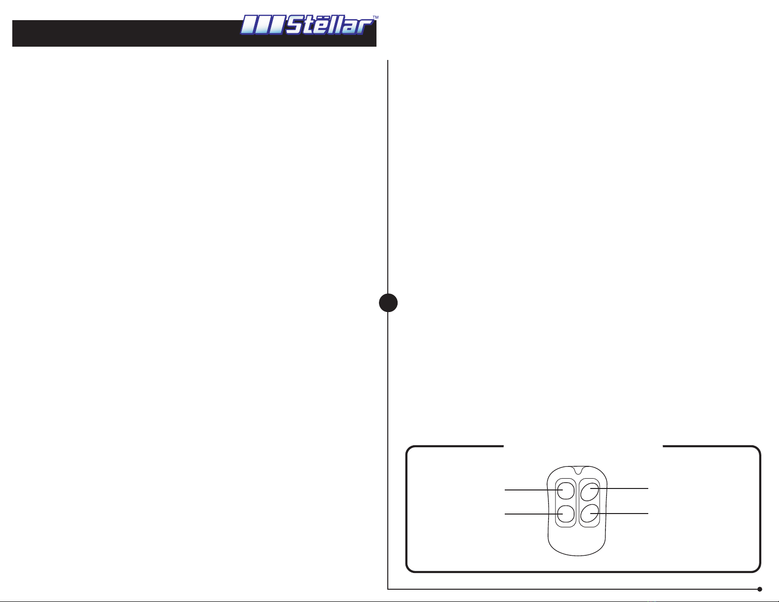
How to use Transmitters
1
CODE LEARNING OR ADDING ANOTHER REMOTE.
1. Turn ke y to the On position.
2. Press and hold the valet button until the system chir ps 3 times to indicate ready to learn status.
3. Press button 1 of the first transmitter once. Then, press Button 1 of the second transmitter
once. The siren will output a confirmation chirp(s) with each remote tr ansmitter that is learned.
For example, after the fi rrst remote transmitter is pr ogr ammed, the siren will chi rp once. After the
second transmitter is pr ogrammed, the siren will chi rp twice. Up to 4 transmitters can be
programmed.
4. If only one remote transmitter needs to be programmed/added, the other rremote tra ansmitter(s)
m ust be repor gr ammed at this time.
5. When done, turn ke y to OFF position to exit code learning mode.
The memory or the codes is NON VOLATILE and will not be er ased by power failure for 10 years
or more.
NOTE: If you place the system in learn mode and teach nothing, the system will exit in 10
seconds. If the 4 location limit is exceeded, the system erases the oldest codes .
ARMING
Press button 1. Siren will chirp once, par king lights will flash once. The system will ar m. In 5 seconds
the system will enter ar ming mode and the starter/ignition. If button 3 is pressed within these 5
seconds, the system will chirp 3 or 2 time s.
2 Chirps: On light impact, the siren chirps 5 time s. On heavy impact, the siren will sound for 60
seconds .
3 Chirps: On both light and heavy impacts,the siren will chi rp 5 time s.
DISARM
Press button 2. The siren will chirp twice and the par king lights will flash twice. The system will
disarm. If passive arming is selected, after 60 seconds the system will enter ar ming mode
autom atically (but will not lock the door s).
NOTE: If the alarm w as triggered during armed mode, the siren will chirp 3 time s.
PANIC
Press button 4 to enter panic mode. After 30 seconds the system will exit this mode and enter
arming mode automatically, dur ing panic mode press button 2 to exit.
SMART PASSIVE ARMING
This system will automatically arm in 60 seconds after you leave the vehicle (After turning of f
the engine, you m ay re ma in in the car indef initely, without the system passively arming. The
c ycle begins w hen you leav e the car). The 60 second timer is reset each time a protected zone
has been opened. The LED flashes rapidly at this time.To avoid locking your keys in the car , the
system will not lock the doo rs.
TO DISABLE PASSIVE ARMING
Turn ke y to OFF position, then press and hold the valet button until the system chirps once.
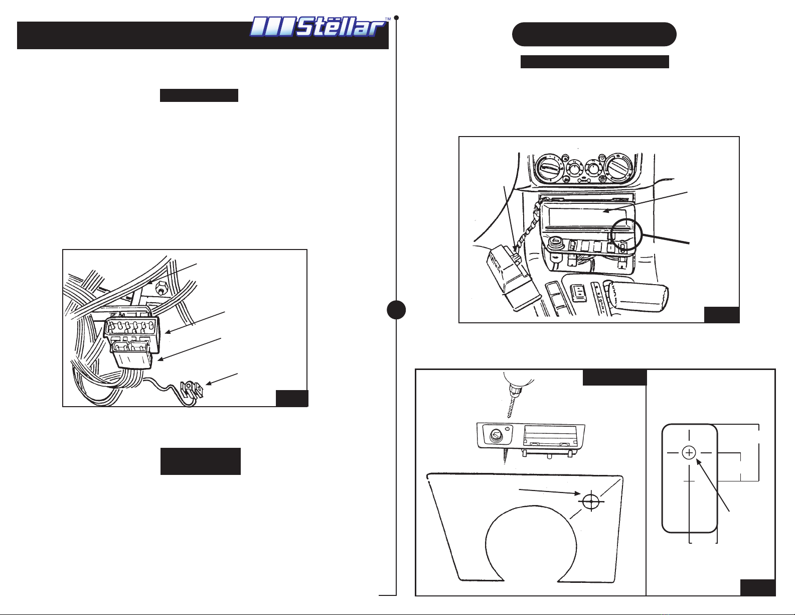
SHOCK SENSOR FEATURE
The shock sensor is built-in to the alarm’ s ma in module. Mount the module tightly on a large
wire harness or a sti ff plastic plate under dash. Avoid mounting the module on metal surfaces
because this will reduce the remote range. Also, av oid installing the module on the steering
column. The shock sensor will be less sensitive to glass , and more to the tires.
To adjust the shock sensor:
1. Turn ke y to the ON position.
2. Hold the va let button until 3 chirps are heard .
3. Turn ke y to OFF position.
4. The system will chi rp once.
5. Wait 2 seconds , then strike the "A pillar" firm ly with your fist.
6. The system will chirp twice to indicate it has lear ned your new setting.
7. When done, turn key to ON position to exit code learning mode.
NOTE: The harder you strike the car, the less sensitive the alarm will be. The softer you strike the
car , the more sensitive the sensor will be.
Do not set too sensitive ,as the alar m will false tr igger often. The system is NO T DESIGNED to
detect rocking or sw aying motion.
TO DISABLE THE SHOCK SENSOR
1. Turn ke y to the OFF position.
2. Hold the va let button until 1 chirp is heard.
3. Press button 2 once within 5 seconds.
4. The alar m will chirp to indicate shock sensor is on or of f and sa ve settings to the EEPROM.
5. The alarm will disarm.
2 Chirps: shock sensor is enabled.
3 Chirps: shock sensor is disabled
VALET/EMERGENCY OVERRIDE BUTTON
To disarm the system in case of a lost remote transmitter ,do the following:
1- Turn ke y to the ON position.
2- Press and hold the valet button. The system will disarm.
IGNITION TRIGGERED DOOR LOCKS
In order to protect the occupants,once the engine has been sta rted, your doors will lock within
5 seconds. The doors will then unlock after the engine has been turned off.
Window, Sunroof , Covert able Top Activation
Press and hold button 3. Only av ailable for BMWRTX series.
Arm
BMWSTXC,
BMWRTXC,
BMWVTXC ONLY
Windows, Sunroof
& Convert. Top
Disarm
Panic
RECIEVER
INSTALLATION GUIDE
automotive security systems
(E-36) 3 Series ( Except 318ti & Z3)
REV2 5.12.03 bmwstx 10/10

13. Remove the two 10mm bolts holding the OBC horn in place. Remove
the OBC horn and disconnect factory siren plug. (Figure 26)
14. Using the wire taps connect the siren wires to the wires from the factory
siren port. (Figure 18)
15. Carefully position all wires out of the way of any moving parts and sharp
edges.
Go to " Final Installation"
1. Test both remotes for operation.
2. TURN ON BMW MODE
a. TURN THE IGNITION TO THE “ON” POSITION.
b. PRESS BOTH BUTTONS ON THE REMOTE AT THE SAME TIME.
- LIGHTS WILL FLASH
c. AGAIN, PRESS BOTH BUTTONS ON THE REMOTE AT THE SAME TIME.
- LIGHTS WILL FLASH
d. TURN THE IGNITION TO THE “OFF” POSITION.
3. Mount the valet button in a hidden location, then plug it into the alarm. This button is used
to program and override the alarm.
4. Check to make sure the system is fully functional.
5. Position the alarm's fuse in an easy to access area for future service.
6. Hide, and clean up all loose wires. Check that alarm wiring does not interfere with any other
vehicle wiring components or moving parts.
7. Reinstall all BMW parts (glove box, center console, knee bolster ect. )
8. Place vehicle security decals on front windows.
Q. When I plug in the alarm the LIGHTS FLASH and nothing happens.
A. This problem is cause by the following:
1. The remotes were not programed, reprogram remotes.
2. The unit does not have power. On some BMW if the alarm was not purchased direct
from BMW 1 of the 4 fuses was not installed. To solve this problem locate the missing fuse
and replace it with a new one. Check your owners manual for fuse location. Usually it is
located under the drivers dash near the firewall.
Q. How do I mount the receiver?
A. Use the cable ties to attach the receiver to a dry part of your vehicle.
Q. What is the Valet button? Were should I mount it and plug it in?
A. The valet button is used to program and override the alarm. Mount the button in a
easily accessible location. Then plug it into the small far left plug on the alarm.
Q. Were should I mount the alarm siren?
A. We recommend mounting the alarm siren in your engine compartment. Make sure the
siren wires do not interfere with any moving parts.
Q. How do I mount the siren?
A. Use the self tapping screws to attach the siren to your vehicle. Make sure that the screw
does not interferer with any part of your vehicle.
Q. How do I use the "wire taps"?
A. Position the factory wire in the upper slot. Insert the other wire in the lower slot. Hold
firmly and close the lid of wire tap; - lock in place.
Q. My horn does not work?
A. Check the wire tap connections at the factory siren plug. Reverse wires.
Q. When I push my remote button nothing happens?
A. Program the remotes (See Operation Sheet) Then check to make sure the alarm has
power.
- Check all connections
- Check fuse
- Check ground
Q. I lost my remote and the alarm is going off. How do I turn it off?
A. Simply turn the ignition switch to the “on” position, then push and hold the valet button.
Q. Can I install the LED in any location?
A. Yes. You may install the LED and shock sensor in any dry location.
Q. How do I turn off the auto arm feature?
A. See "Operation" Sheet "To Disable the Passive Mode"
Q. Why is the purple wire not connected, and what does it do?
A. The purple wire is for for remote start, trunk pop, or windows. Please contact local
dealer for additional upgrades.
Questions? Please call our tech line at 503-693-191
9
Fig 26
Trouble Shooting
Final Installation
REV2 5.12.03 bmwstx 9/10
RECIEVER
INSTALLATION GUIDE
automotive security systems
(E-36) 3 Series ( Except 318ti & Z3)

For vehicles with M60 Engine
6. Disconnect the negative cable from the battery located under the rear
seat.
7. Remove the four screws that hold the engine top cover trim panel to
intake manifold. (Figure 22)
8. Remove the battery "+" terminal mounting bolts, and diagnostic connector
mounting clip. Let these components hang freely. (Figure 22)
9. Locate the coolant reservoir and remove the overflow tube. Remove the
reservoir's two securing nuts to gain access to the blower motor access
panel. (Figure 23)
10. Carefully remove the black plastic heater valve cover. (Figure 23)
11. Remove the four nuts that secure the black metal wire conduit cover to
the blower motor access panel. Now remove the five 7mm screws that hold
the black rubber coated blower motor panel to the bulkhead. Finally pull
the weather seal up. (Figure 24)
12. Remove the blower motor access panel and the black plastic blower
motor shield from the bulkhead cavity. (Figure 25)
8
Fig 22
Fig 23
Fig 24
Fig 25
REV2 5.12.03 bmwstx 8/10
aa
RECIEVER
INSTALLATION GUIDE
automotive security systems
(E-36) 3 Series ( Except 318ti & Z3)

5 Series (E-34) & 7 Series (E-32)
5 series vehicles equipped with an onboard computer have a factor y
installed OBC horn that acts as the alarm sounding device. In most cases
you will need to replace the OBC horn with the alarm siren.
1. Mount the siren in your engine compartment.
2. Run the wires from the siren to the grey 2 pin factory siren plug. (Figure 18)
- This grey 2 pin factory siren plug is located in the firewall by the blower
motor.
3. Remove the black plastic cover from the left side of the "E" box. (Figure 19)
3. Using the wire taps connect the siren wires to the wires from the factory
siren port. (Figure 18)
(
Note: If vehicle is equipped with an on board computer disconnect OBC
horn plug from the factory siren plug.)
4. Carefully position all wires out of the way of any moving parts and sharp
edges. Go to " Final Installation" Pg. 9
4. Carefully remove the metal support bracket by unscrewing the two
securing screws. (Figure 20)
5. Remove blower motor access panel by removing the two securing nuts.
(Figure 21) Go to step 10.
7
Side Front
Siren
Plug
Siren
Wire
Tap
Wire
Tap
Factory Wire
Loom
Fig 18
Fig 19
Fig 20
Fig 21
Grey
or Black
REV2 5.12.03 bmwstx 7/10
RECIEVER
INSTALLATION GUIDE
automotive security systems
(E-36) 3 Series ( Except 318ti & Z3)

Siren
Plug
Fig 17
LED
Wood Trim Panel
Fig 15
(E-36) 3 Series (318ti & Z3 )
1. Mount the siren in your engine compartment.
2. Run the wires from the siren to the factory 2 pin siren plug.
This factory siren plug can be located in 2 spots:
a. Behind right-hand (passenger's) side headlight's wire loom. (Figure 16)
- Trace the wiring from the headlights back to the factory siren plug.
Siren Installation
Siren Plug Behind
Right Headlight
Fig 16
Hood
Switch
NOTE: FOR Z3 2.8L The siren plug is located below your brake booster in
your engine competent.
UPDATE
1. You may mount the LED in any dry location. We recommend mounting
the LED in the wood trim panel to the right of the steering column.
(Figure 15)
Carefully
remove the wood trim from the panel with a sliding
and pulling action.
2. Carefully drill a hole for the LED using stencil ( Figure 15).
3. Mount the LED in the hole and run the wires to the receiver which is now
mounted under the dash.
4. Plug in the LED terminal into the receiver.
Go to " Siren Installation"
6
b. Below the battery terminal between the passenger side's firewall and
strut tower. (Figure 17)
(E-32) 7 Series
REV2 5.12.03 bmwstx 6/10
RECIEVER
INSTALLATION GUIDE
automotive security systems
(E-36) 3 Series ( Except 318ti & Z3)

(E-34) 5 Series
You may mount the LED in the fog light bezel, or the rear cigarette bezel.
Cigarette Lighter Bezel
1. Mount the LED in the cigarette lighter bezel at the rear of the center
console. ( Figure 13)
- Place a screwdriver along the bottom edged (along carpeting) and lift
up carefully.
- Disconnect cigarette lighter wiring.
2. Drill a hole for the LED.
3. Mount the LED in the hole and run the wires to the receiver which is now
mounted under the rear seat.
4. Plug in the LED terminal into the receiver.
Go to " Siren Installation" Pg. 6
Fog Light Bezel
1. Mount the LED in the foglight switch bezel on the dash. (Figure 14)
- Place a screwdriver along the right side and lift up carefully.
- Disconnect cigarette lighter wiring.
2. Drill a hole for the LED.
3. Mount the LED in the hole and run the wires to the receiver which is now
mounted under the rear seat (you will need to extend the wire).
4. Plug in the LED terminal into the receiver.
Go to " Siren Installation"
5
Fig 12
Remove
Knock Out
Panel
BMWSTX Receiver
LED Harness
Fig 13
Cigarette
Lighter
Bezel
LED
Fig 14
Foglight Switch Bezel
LED
4. Run the LED wires to the receiver which is now mounted in the glove box.
(Figure 12)
5. Plug in the LED terminal into the receiver.
Go to " Siren Installation" Pg. 6
REV2 5.12.03 bmwstx 5/10
RECIEVER
INSTALLATION GUIDE
automotive security systems
(E-36) 3 Series ( Except 318ti & Z3)

5. Mount the BMWSTX's unit securely to the vehicle.
Go to " LED & Sensor Installation"
(E-32) 7 Series
1. Carefully remove the drivers side knee bolster to gain access under the
dash and steering column.
2. Locate the black 12 pin alarm port. This port is located approximately 5
inches to the left of the brake pedal bracket. The alarm port is mounted
between a white bracket and a white 4 pin connector against the firewall.
( Figure 9)
3. Plug in the BMWSTX connector to your BMW's 12 pin alarm port.
4. Using the wire tap connect the single RED wire from BMWSTX's alarm
harness to the single black female pin wire. ( Figure 9 )
(Note: On early production vehicles this wire was installed. IF YOU DO NOT
HAVE A SINGLE BLACK FEMALE PIN LEAVE RED WIRE DISCONNECTED)
LED & Sensor Installation
4
5.5 mm
(7/32)
318ti LED Stencil Fig 11
318ti ONLY
20 mm
10 mm
9 mm
5.5 mm
(7/32)
2. Use the stencil to drill a hole for the LED. ( Figure 11)
3. Mount the LED in the hole.
3 Series including 318ti & Z3
1. Mount the LED in a knock out panel located in the center console.
(Figure 10&11)
- Pop out the information display.
- Lift up the center console panel and remove the knock out panel.
- Z3 Roadsters : Simply remove knock out panel from center console.
Fig 10
Information
Display Center
Console
Panel
Knock Out
Panel
12 Pin Alarm Port
(black)
4 Pin Connector
(white ) not used
White Bracket
Black Female Pin
( Connect to red wire
w/ wire tap )
Fig 9
(E-34) 5 Series
1. Carefully remove the rear seat bottom.
2. Locate the black 12 pin alarm port. This port is located at the extreme
right of the rear seat well.
3.
IMPORTANT! CUT the RED LOOP wire on pin 11.
4. Plug in the BMWSTX connector to your BMW's 12 pin alarm port.
5. Mount the unit securely to the vehicle. Make sure the wire harness and
unit does not interfere with the seat bottom or battery.
Go to " LED & Sensor Installation"
REV2 5.12.03 bmwstx 4/10
RECIEVER
INSTALLATION GUIDE
automotive security systems
(E-36) 3 Series ( Except 318ti & Z3)

Z3 Roadster
1. Carefully remove the passenger glove box assembly by removing the
screws shown in figure 7.
2. Locate and remove the passenger's lower side trim panel by removing
the 3 plastic retainers (turn 90 degrees).
3. Remove the glove box assembly by lifting up the left side in order to clear
the securing tabs.
3. Remove the passengers knee bolster by unscrewing the three 10mm hex
head bolts. (Figure 5)
Knee
Bolster
Fig 5
4. Remove the lower trim panel. (Figure 3)
5. Plug in the BMWSTX connector to your BMW's 12 pin alarm port. (Figure 6)
6. Using the wire tap connect the single RED wire from BMWSTX's alarm
harness to the single black female pin wire.
(Figure 6)
(Note: On early production vehicles this wire was installed. IF YOU DO NOT
HAVE A SINGLE BLACK FEMALE PIN LEAVE RED WIRE DISCONNECTED)
7. Mount the unit securely to the vehicle. In some cases you will need to
remove part of the lower trim panels insulation. (Figure 3)
Go to " LED & Sensor Installation" Pg 4.
Fig 7
4. Plug in the BMWSTX's connector to your BMW's 12 pin alarm port.(Figure 8)
5. Using the wire tap connect the single RED wire from BMWSTX's alarm
harness to the single black female pin wire.
( Figure 8 )
(Note: On early production vehicles this wire was installed. IF YOU DO NOT
HAVE A SINGLE BLACK FEMALE PIN LEAVE RED WIRE DISCONNECTED)
6. Mount the unit securely to the vehicle.
Go to " LED & Sensor Installation" Pg. 4
3
12 Pin
Alarm
Port
BMWSTX Connector
Fig 6
Wire Tap
Black Female
Pin
Red Wire
BMWSTX Connector
& 12 Pin Alarm Port
Single Black Pin
Female Pin
BMWARP
Receiver
Red Wire
Fig 8
REV2 5.12.03 bmwstx 3/10
RECIEVER
INSTALLATION GUIDE
automotive security systems
(E-36) 3 Series ( Except 318ti & Z3)

(E-36) 318ti
1. Carefully remove the passenger glove box assembly by removing the
screws shown in figure 4.
2. Remove the glove box assembly and disconnect all electrical wiring
connections.
1. Carefully remove the passenger glove box assembly by removing the
following screws. (Figure 1)
- Remove the individual screws from behind each of the two vents above
the glove box.
- Open the glove box and remove the two trim caps.
- Remove the eight screws shown in Figure 1.
- Remove the glove box light to gain access to the 10mm bolt. Remove
the bolt.
Trim Caps Trim Caps
Glove Box Light Removed To
Gain Access to 10mm Bolt
Screws
Fig 1
12 Pin Alarm Port
BMWSTX Connector Knee Bolster
Fig 2
Black Female
Pin
Wire
Tap
Red
Wire
BMWSTX Unit
Installation
Cut-Out
Lower
Trim
Panel
12 Pin
Alarm Port
Fig 3
Trim
Cap
Remove Screws as Shown.
Fig 4
2
2. Remove the glove box assembly and disconnect all electrical wiring
connections.
3. Plug in the BMWSTX connector to your BMW's 12 pin alarmport.
( Figure 2)
4. Using the wire tap connect the single RED wire from BMWSTX 's alarm
harness to the single black female pin wire.
( Figure 2 )
(Note: On early production vehicles this wire was installed. IF YOU DO NOT
HA
VE A SINGLE BLACK FEMALE PIN LEA
VE RED WIRE DISCONNECTED)
5. Mount the unit securely to the vehicle. In some cases you will need to
remove part of the lower trim panel's insulation to make the receiver fit.
(Figure 3)
Go to " LED & Sensor Installation" Pg. 4
RECIEVER
INSTALLATION GUIDE
automotivesecurity systems
(E-36) 3 Series ( Except 318ti & Z3)
REV2 5.12.03 bmwstx
2/10

©2003 The Hoffman Group L.L.C. All Rights Reserved. All other trademarks are the property of their respective owners.
Parts List
BMWSTX & BMWSTX-C
BMWRTX & BMWRTX-C
Rev 2 5.12.03
INSTALLATION GUIDE
BMW COMPATIBLE
ALARM SYSTEM
• 3 Wire taps
• Three wire ties
• Instructions
• 2 Transmitters
• Receiver
• Siren
• LED
• Valet button
bmwstx 1/10
Grab some popcorn! Autolöc
offers installation movies on CD
ROM to insure quick and simple
installation. Each movie offers
professional step by step installation
Got the Movie?
Installation Video
WWW.STELLAR.COMTECH SUPPORT: 503.693.1918
automotive security systems
Congratulations on your purchase of a Stellar vehicle system! Your
satisfaction and enjoyment is important to us. In the event that you
experience any installation or operation problems with your system please feel
free to contactus directly. Many problems can be easily solved without
returning the system to your local dealer. We hope you enjoy your new
Stellar vehicle security system and don't forget to fill out your warranty card!
• Wire Loom
BMWVTX
BMWVTXC
This manual suits for next models
5
Table of contents
Other stellar labs Car Alarm manuals
Popular Car Alarm manuals by other brands

Audiovox
Audiovox Prestige APS-15CH owner's manual

jablotron
jablotron CA-1803BT Athos installation manual

LaserLine
LaserLine 361 Fitting instructions

CompuSTAR
CompuSTAR CompuStar SHF 2W-AS user guide

Leisure Technologies
Leisure Technologies WITI Operations & installation guide

jablotron
jablotron CA-1802 athos user manual