Gemini 7057 User manual

7057
7056
...................................
...........................................................
CERTIFICAT D' INSTALLATION
INSTALLATION CERTIFICATE
EINBAUBESCHEINIGUNG
Je soussigné,installateur,certifie d'avoir fait personnellement l'installation du dispositif d'alarme
du véhicule ci décrit,conforme aux instructions du constructeur.
The undersigned,qualified installer,attests to have personally fitted the here described Vehicle
Security system following the manufacturer instructions.
Der Installateur bestätigt mit seiner Unterschrift, daß die Alarmanlage in dem genannten Fahrzeug
nach Vorgaben Des Herstellers eingebaut wurde.
Signature,Firma,Assinatura,Unterschrift .................................................................
CERTIFICADO DE INSTALACION
El que suscribe, instalador, certifica el haber seguido personalmente la instalación del dispositivo
de alarma del vehículo descrito a continuación, de acuerdo con las instrucciones del fabricante.
CERTIFICATO DI INSTALLAZIONE.
Il sottoscritto,installatore,certifica di aver eseguito personalmente l'installazione del dispositivo
di allarme del veicolo descritto qui di seguito,conformemente alle istruzioni del fabbricante.
No forest has been destroyed to
produce this 100% recycled paper.
by GEMINI TRADING S.r.l. Via Luigi Galvani 12 21020 Bodio Lomnago (VA) Italia
Tel. +39 0332 943211 - Fax +39 0332 948080
By :
Da :
Par :
Von :
Por :
Sold on :
Venduto il :
Vendu le :
Verkauft am :
Vendido el :
Type of product :
Tipo di prodotto :
Produktartikel :
Type de dispositif:
Dispositivo ciclo :
Auto
Car
Véhicule
Fahrzeug
Veículo
7208
0682
7057
7056
AC2506-REV.00/04/01

DESCRIPTION
Gemini 7057
Gemini 7057 is a compact, self-powered alarm with sensors and siren. Studied for vehicles
equipped with original transmitter and direction indicator lights flashing while opening and
closing the vehicles door.
Gemini 7056
As Gemini 7057 without self-power and engine immobilisation.
FUNCTIONS
-Control for alarm arming/disarming through the direction indicators lights and controls for the
vehicles lock actuators.
-Blinker and electronic siren.
-Perimetrical protection and volumetric protection only for Kit 7057US and Kit 7056US.
-Positive and negative control for vehicles equipped with “Pack-comfort” system.
-Engine immobilisation (only 7057).
-Negative control external additional siren.
-Automatic arming.
-Absorptionsensor.
-LED’s memory.
The alarm system is supplied with two mechanical keys for the emergency release.
INSTALLATION INSTRUCTIONS (for the installer).
-It is necessary to memorise the arming/disarming sequence controls through the direction indicator
lights after the wiring connections.
-The alarm wiring harness must be positioned away from the vehicle high voltage wires in order to
avoid interference which could generate wrong working of the system.
-On vehicles with catalytic converter, the engine immobilisation must be carried out on the fuel
pump.
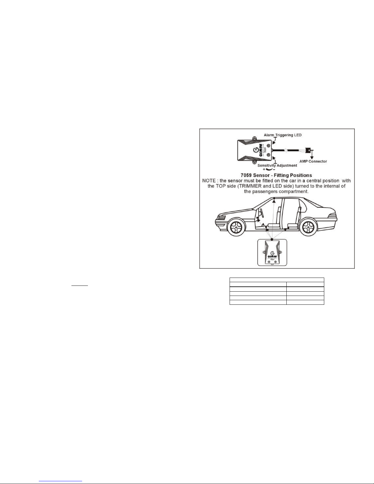
-For systems with volumetric sensors (art. 7057US e 7056US), the transducers must be installed at
the top of each windscreen pillar, far from the ventilation or the conditioning air outputs.
-Note: to obtain the correct working of the automatic arming and perimetrical protection functions,
connecttheGREEN-BROWN wire to the boot/door switches.
DIP SWITCHES PROGRAMMING TABLE
1 ON Current absorption sensor ON
1 OFF Current absorption sensor OFF
2 ON Passive arming ON
2 OFF Passive arming OFF
3 ON Arming/disarming acoustic signalling OFF
3 OFF Arming/disarming acoustic signalling ON
4 ON Arming/disarming control through the direction indicator lights and the
vehicle lock actuators.
4 OFF Arming/disarming control through the direction indicator lights.
ATTENTION: SELECT THE DIP-SWITCHES BEFORE TURNING THE EMERGENCY KEY TO ON.
ACCORDING TO THE RULES POSITION THE DIP-SWITCH N.1 TO OFF.
WIRING CONNECTIONS
(DISCONNECT THE NEGATIVE TERMINAL OF THE BATTERYAND ONLY RE-CONNECT AFTER THE
INSTALLATION IS COMPLETE)
FUNCTIONS WIRE COLOURS
Earth êê BLACK initialled M
Battery positive terminal êê BLACK initialled R
Engineimmobilisation êê 2x GREY initialled H
Ignitionlive êê YELLOW
Door pin switch êê GREEN-BROWN
Boot/bonnet pin switch êê BLACK initialled V
Positive alarm armed êê PINK
Sensors inlet êê GREEN-BLACK
Negative comfort control additional siren êê YELLOW-BLACK
Positive Comfort control êê RED-BLACK
Negative Comfort control êê WHITE-BLACK
Arming/disarming control through the direction
indicator lights + Blinker. êê 2 x ORANGE
Arming Synchronism control êê YELLOW-BLUE
Disarming Synchronism control êê GREEN-BLUE
NOTE: connect always the synchronism controls (YELLOW-BLUE and GREEN-BLUE wires) to
the two polarity reversal wires of the L.H.S. actuators lock.
The wiring harness is supplied with two connectors; connect the 4 pin connectors to the ultrasonic
module and the two pin connector to the LED.
SELF-LEARNING FUNCTION OF THE DIRECTION INDICATOR LIGHTS
FLASHING SEQUENCES.
IMPORTANT:BEFORE ACTIVATING THE SELF-LEARNING FUNCTION, IT IS NECESSARY TO SELECT
CORRECTLY THE DIP-SWITCHES AND TO CARRY OUT THE WIRING CONNECTIONS. DO NOT USE THE
TRANSMITTER BEFORE HAVING ACTIVATED THE SELF-LEARNING FUNCTION.
THIS FUNCTION ALLOWS MEMORISING THE SEQUENCE OF THE DIRECTION INDICATOR LIGHTS
FLAHING WHILE OPENING OR CLOSING THE DOOR.
To activate the self-learning function proceed as follows:
-Position the alarm key toOFF.
-Turn the ignition key toON.
-Position the alarm key toON.
-The LED of the alarm lights.
-Turn the ignition key toOFF.
-Close the vehicle door with the original transmitter. The LED stops lightning at the first
direction indicator lights flashing. One audible tone signals the door closure.
Note: wait always till the audible tone before learning the door opening.
-Open the vehicle door with the original transmitter. The LED stops lightning at the first
direction indicator lights flashing. Two audible tones signal the end of the self-learning
operation of the 7057 or 7056 system.
THE ACOUSTIC SIGNALLING CAN BE OBTAINED ALSO WITH THE DIP-SWITCH
N. 3 TO ON.

WORKING DESCRIPTION
-ALARM ARMING WITH ORIGINAL TRANSMITTER:push on the closure button of the vehicle
original transmitter. The arming and the vehicles locks closure are signalled by the original
flashing of the direction indicator lights and by one beep of the alarm system (dip-switch 3 to
OFF). During the first 30 seconds from the alarm arming, the LED lights fix to show the
neutral time when all inputs are isolated. At the end of the neutral time, the LED will flash to
show the inlets activation.
NOTE: if the vehicle emergency switch is pushed it is not possible to arm the alarm. The
alarm will arm only if the direction indicator lights original system stops the emergency
flashing.
-ALARM PERIOD:the alarm phase is generated from the excitation of one or more inlets. The
alarm period is 30 seconds for each alarm cycle. The direction indicator lights flashes 5
seconds after the alarm cycle for 4 consecutive times, followed by a 5-sec. interval.
The alarm system can be disarmed with the original transmitter during the 5-sec. interval or at
the end of the alarm cycle.
-ALARM DISARMING WITH THE ORIGINAL TRANSMITTER: push on the opening button of the
vehicle original transmitter. One flashing of the direction indicator lights signal the door
opening and 3 audible tones will confirm the disarming of the system (dip-switch No. 3 to
OFF); 5 audible tones if an alarm condition has occurred.
NOTE: the alarm system will disarm only at the end of the sequence of the direction indicator
lights flashing or at the end of the 3 or 5 beeps.
SPECIAL FUNCTIONS
ALARM AUTOMATIC ARMING:This function allows the system to arm automatically 30 seconds
from the engine switching off or the door opening. To obtain this function, position the dip-
switch N°2 to ON; connect the Green-brown wire to the door pin switch and the Yellow wire to
the ignition live (+15/54).
LED’S MEMORY. While alarm disarming it is possible to identify the alarm triggering cause.
Turning the ignition key to ON, the flashing LED will repeat the alarm triggering cause for 4
times.
LED flashing Alarm triggering Alarm cycles
YlYAbsorption sensor 5
YYlYY Doors, boot and bonnet buttons 5
YYYlYYY Ignition live UNLIMITED
YYYYlYYYY External sensor (Green-Black wire) 5
lLED OFF (2 seconds) YLED ON (1 second)
The neutral time is 30 seconds for each alarm triggering.
TECHNICAL DATA
Power supply 10,5 ÷14,5VDC
Max. current absorption 10 mA
Working temperature -40° + 85°
Direction indicator lights contact capacity 8A a 20° C
Engine immobilisation contact capacity 8A a 20° C
Alarm cycle period 30 seconds
Max. current – positive alarm armed (+A) 1A
Max. current positive comfort 500 mA
Max. current negative comfort 100 mA
Audible tone >118dB
ULTRASONIC MODULE DESCRIPTION
5123GE (for 7057US and 7056US models)
The 5123 sensors protects the vehicle passenger compartment with ultrasonic waves; the
opening of a door or a movement inside the vehicles are detected by the sensor which triggers
the alarm.
Installation instructions
The connection of the sensor to the alarm system is easy as the alarm wiring harness is supplied
with an appropriate plug.
Put the connectors of the sensor’s ultrasonic heads in the appropriate seats: RED for the connection of
the TX head; WHITE for the connection of the RX head.
Ultrasonic adjustment
1. Lower one of the front windows approximately 20 cm.
2. Adjust the sensor to a minimum sensitivity;
3. Arm the alarm and verify that all doors are completely closed.
4. Put a hand through the open windows and move it; the LED of the module will light red.
Increase the sensitivity till the alarm triggers.
TECHNICAL DATA
Working Voltage 9÷16VDC
Current absorption 2,5mA
Working temperature -30°C +85°C

DESCRIPTION OF THE MODULE GEMINI 7059.
GEMINI 7059 protects the vehicle detecting attempts to break into the passengers compartment
by the emission of an electromagnetic field (frequency = 2,45 GHz).
The working of the sensor is based on the reflection of the electromagnetic waves when a object,
made of a conductive material, is located on the field.
The measurement of the reflected waves can detect the intrusion and then trigger the alarm
device connected to the sensor.
GEMIN 7059 is insensitive to air movements (wind, thermal air drift, etc.), for this reason it’s
suitable to be fitted on pick-up vehicles, convertible cars and vehicle equipped by a sliding
sunroof.
Due to the fact that the insulating materials are transparent to the electromagnetic waves it’s
possible to fit the sensor module in a hidden position, e.g. under the passengers compartment
carpet.
FITTING INSTRUCTIONS.
In order to obtain the correct working of the sensor module it’s very important to identify the
best fitting position depending on the vehicle model.
In any case, it’s important to remember that, the complete protection of the vehicle internal
space can not be obtained using a high-frequency sensor module.
The sensitivity adjustment must be done in order to avoid false alarm triggering, due to objects
in movement outside the vehicle (e.g. people, other vehicles or motorbikes).
To increase the false alarms protection it’s important to comply the following fitting rules :
a) the connection cable of the sensor mustbe fitted and routed far from the module case.
b) the module must be fitted far from coin holders or glove compartments.
c) avoid all metal mobile objects in the passengers compartment.
To find the proper fitting position, please see the fitting diagram contained in this fitting manual.
ELECTRIC CONNECTIONS.
The connection of the module to the alarm system is very easy as the wiring harness is equipped with a
proper connector.
SENSITIVITY ADJUSTMENT.
GEMINI 7059 is provided by a sensitivity adjustment control, by this it’s possible to set the sensor
sensitivity from a MINIMUM value (NOT ZERO) to a MAXIMUM value.
To help the adjustment operation the module is provided by a RED led located on the top side of the sensor
case. This led is lighted for 4 sec. whenan alarm condition is detected. (NOTE : between an alarm condition
and the following is present a delay time of 5 sec.).
ADJUSTMENT PROCEDURE :
1) Set the adjustment control to the MAXIMUM value (clockwise direction).
2) Close all doors, windows, boot and bonnet, then arm the alarm unit connected to the sensor module and
wait for the end of the arming delay time, or set on the DIAGNOSTIC MODE
3) Move the hands near the vehicle windows (lateral, front and rear) and make sure that the sensor does
not activate.
4) If the sensor activate reduce the value of the adjustment control (anti-clockwise direction), then repeat
the test described on the point 3).
5) If the test result is positive, (no false alarms detected moving the hands near the windows), disarm the
alarm unit and open one of the front windows.
6) Arm the alarm unit again, or set on the DIAGNOSTIC MODE, and check the correct alarm triggering
moving an arm inside the passengers compartment.
TECHNICALDATA.
EM Field Frequency 2,45GHz
±
2,45MHz
OperatingTemperature -40°C
÷
+85°C
Alarm Triggering pulse Negative 4 sec.
Operating Power Supply 10
÷
15VDC
CurrentConsumption
≤
5mA
This device is guaranteed against construction or working faults for 12 months from purchase date and for
a maximum of 24 months from manufacturing. The manufacturer declines every responsibility for any
possible defect or failure to the device and to the vehicle’s electric system due to incorrect installation or to
the alteration of the indicated Technical Features.

4 OFF
4ON
ON
ON
2
2
1
1
3
3
4
4
FITTING DIAGRAM
YELLOW
+30
GREEN-BROWN
BLACK marked V
BLACK marked M
Red
Black
YELLOW-BLUE (ON)
GREEN-BLUE (OFF)
Synchronism control
ORANGE
ORANGE
ORANGE
ORANGE
ORANGE
ORANGE
YELLOW-BLUE
GREEN-BLUE
BLACK marked H
BLACK marked H
8A
MAX !
EARTH
YELLOW-BLACK
BLACK marked R
CLAMP
CLAMP
5A
5A
5A
5A
5A
5A
WHITE-BLACK
(Negative Comfort)
RED-BLACK
(Positive Comfort)
Comfort
7057
7057
7057
Arming, disarming through the direction indicator lights.
Arming, disarming through the direction indicator lights
and original slave motors.
OPEN
COMMUN
CLOSE
Positive closure
Positive opening
Note : positive closure and opening are the reversal polarity wire of the motor.
Original slave motor
NOTE :
The BLACK wires have the identification
mark at the end.
Supplementary Siren
with negative control
Engine immobilisation
Fuel pump
Solenoid valve-diesel
Ignition Key
Direction Indicator Lights
Boot/Bonnet Pin Switch
Door Pin Switch
Pink
Brown
Green/black
+-
5123
Ultrasonic module
15A
Battery
12 VOLT
+
-
7059
This manual suits for next models
1
Other Gemini Car Alarm manuals
Popular Car Alarm manuals by other brands

Viper
Viper 5606V owner's guide

Crime Guard
Crime Guard 328i3 Operation manual

CrimeStopper
CrimeStopper Super Page V CS-2014TW2 Operation instructions

Silencer Security Systems
Silencer Security Systems SLRF8 owner's manual

Black Widow
Black Widow BW 550 owner's manual

Code Alarm
Code Alarm CA1B5 owner's guide

CrimeStopper
CrimeStopper SP-302 operating instructions

Blaupunkt
Blaupunkt CA3.0 Operating and installation instructions

Magicar
Magicar M871A installation guide

Easyguard
Easyguard EC003 User Manual & Wiring Diagram

Directed Electronics
Directed Electronics Hornet 563T installation guide

Avital
Avital 2100 installation guide