STEP Snowmelt User manual

STEP®Snowmelt
Installation Manual
Low Voltage System

2 | P a g e
Copyright ©Electro Plastics, Inc. / STEP Warmfloor®September 2015
Contents
STEP®SNOWMELT SYSTEM ........................................................................................................................ 3
BENEFITS .................................................................................................................................................................... 3
INSTALLATION GUIDELINES ........................................................................................................................ 4
IMPORTANT INSTALLATION GUIDLINES........................................................................................................................... 4
WARNING .................................................................................................................................................................... 4
BEFORE STARTING ..................................................................................................................................... 5
DESIGN AND CALCULATIONS ......................................................................................................................................... 5
SUPPLIED PARTS .......................................................................................................................................................... 5
DESIGN AND CALCULATION ........................................................................................................................ 6
AC POWER SUPPLY ....................................................................................................................................................... 6
LOW VOLTAGE DC CONTROLLER..................................................................................................................................... 6
ELEMENT TYPE AND WATTAGE ....................................................................................................................................... 7
WIRE GAUGE AND LENGTH ............................................................................................................................................ 7
PRODUCT SPECIFICATIONS......................................................................................................................... 8
CONSTRUCTION ........................................................................................................................................................... 8
APPLICATION ............................................................................................................................................................... 8
HEATING ELEMENT MODELS .......................................................................................................................................... 9
INSTALLATION......................................................................................................................................... 10
1. PLAN ..................................................................................................................................................................... 10
2. INSTALL ................................................................................................................................................................ 10
3. CONNECT............................................................................................................................................................... 11
4. COVER................................................................................................................................................................... 11
MAKE THE CONNECTIONS............................................................................................................................................ 12
SYSTEM DESIGN......................................................................................................................................................... 13
ELECTRICAL GUIDELINES.......................................................................................................................... 14
LOW VOLTAGE ELECTRIC RADIANT HEATING EQUIPMENT ............................................................................................... 14
AC POWER SUPPLY WIRING DIAGRAM ........................................................................................................ 15
DC CONTROLLER WIRING DIAGRAM ........................................................................................................... 16
FAIL SAFE WIRING ................................................................................................................................... 17
CONTROLS .............................................................................................................................................. 18
STEP TOUCH® THEMOSTAT .......................................................................................................................................... 18
WARRANTY REGISTRATION AND COVERAGE ............................................................................................... 19
WARRANTY REGISTRATION CARD ................................................................................................................................. 20
TROUBLESHOOTING ................................................................................................................................. 22
POWER SUPPLY .......................................................................................................................................................... 22
HEATING ELEMENT ..................................................................................................................................................... 23

3 | P a g e
Copyright ©Electro Plastics, Inc. / STEP Warmfloor®September 2015
STEP®SNOWMELT SYSTEM
STEP®Snowmelt is a heating solution to melt snow and ice on entrances, walkways, driveways,
ramps, patios, etc. The snow melt system eliminates shoveling snow and protects pedestrians
from slippery ice or snow covered driveways and sidewalks.
STEP®Snowmelt systems consist of thin, flat and flexible heating elements that operate on low
voltage (AC or DC) and are custom designed for each individual application. These durable,
lightweight heating elements can be stapled or nailed through as long as the two embedded bus
braids on each side of the element are not penetrated.
STEP®Snowmelt heating elements are powered by a 24V low voltage AC Power Supply or DC
Controller. The heating elements, which can be cut to size on site are available in different
widths and protected by a chemically, inherently inert and dielectric insulation. This liner
protects against physical damages and aggressive materials and allows heating elements to be
installed under concrete or selected other surfaces.
STEP®Snowmelt heating element is made of a homogeneous, semi-conductive polymer, which
by nature is self-regulating. This self-regulating, positive temperature coefficient (PTC), Nano-
technology allows them to heat with maximum power in cold environments and use less
electricity as their temperature increases. This minimizes power consumption and reduces
operating costs by as much as 60% compared to conventional electric cable systems.
BENEFITS
STEP®Snowmelt is a flat, flexible and thin heating element.
The heating element can be cut to length at the jobsite.
The polymer material can be penetrated without affecting the conductivity, but the two
conductors on each side must not be penetrated.
The element is strong and durable.
STEP®Snowmelt has the ability to self-regulate - as the material gets warmer, less
electricity passes through the plastic - therefore it is extremely energy-efficient.
The element acts on its whole surface as a sensor and cannot overheat.
This heating system is very versatile and can be used for residential, commercial and
industrial applications.
Avoids shoveling snow, and keeps pedestrians safe.
Low operating costs compared to alternative snow melting systems.

4 | P a g e
Copyright ©Electro Plastics, Inc. / STEP Warmfloor®September 2015
INSTALLATION GUIDELINES
IMPORTANT INSTALLATION GUIDLINES
Choose qualified personnel who are familiar with the STEP®Snowmelt heating system.
Make sure that all materials used are approved for the specific application and have no
adverse compatibility with the heating elements.
The polymer material can be penetrated, but do not damage the two bus braids and lead
wires on each side of the element.
Use only components recommended by the manufacturer.
Electrically check and measure the heating system before covering the heating elements.
The installation shall be made in accordance with local codes, ordinances, trade practices,
and manufacturers' instructions.
Read and follow the installation instructions to assure that the calculations and the
heating system installed are done according to the specified application.
STEP®Labels shall be provided with the heating product and should be filled out and
affixed in the place indicated:
oCAUTION label is to be attached to the junction box.
oWARNING label is to be attached to the service panel.
WARNING
HEATING ELEMENTS SHOULD NOT TOUCH, CROSS OR OVERLAP AT ANY POINT.
DO NOT ENERGIZE ROLLED UP HEATING ELLEMENTS.
DO NOT NAIL OR STAPLE ANY METALLIC OBJECT THROUGH TERMINALS AND BUS
BRAIDS.
HEATING ELEMENT IS REQUIRED TO BE INSTALLED BY QUALIFIED PERSONNEL IN
ACCORDANCE WITH LOCAL AND NATIONAL CODES SUCH AS NEC IN U.S., CEC IN
CANADA.
HEATING ELEMENT SHOULD BE TESTED AND MEASURED BEFORE BEING COVERED.
READ AND FOLLOW ALL INSTRUCTIONS.
These installation instructions assume that the STEP®Snowmelt system has been designed by
Electro Plastics, Inc. or a distributor of Electro Plastics, Inc. and is being installed according to
the proposed Design Specifications, all Terms & Conditions of Sale, and Limited Warranty
provided with a STEP®Snowmelt quotation.
For more information, contact Electro Plastics, Inc. at 877-783-7832 or the distributor that
originally provided the quotation. You can also go to www.warmfloor.com.

5 | P a g e
Copyright ©Electro Plastics, Inc. / STEP Warmfloor®September 2015
BEFORE STARTING
DESIGN AND CALCULATIONS
The installation shall be calculated and a layout made to determine the materials
required.
The more specific the layout the easier will be the installation. Indicate for each area:
oExact measurements of the areas(s) to be heated.
oPlacement and number of strips of elements.
oLength and wattage per element strip.
oLocation of power source, including electrical box, control and power supply(s).
oWire size and length according to load and distance to the power source.
oSize of AC power supply or DC controller and load distribution on the interface
boards.
SUPPLIED PARTS
STEP®Heating Element
STEP®AC Power Supply
STEP®DC Controller
MEP-30-70W-24V
MEP-23-80W-24V
EPI-LX-R-500W-24V
EPI-LX-R-1000W-24V
EPI-LX-R-1500W-24V
EPI-DC-M1
EPI-DC-M2
EPI-DC-M3
EPI-DC-M4
EPI-DC-M5
EPI-DC-M6
EPI-DC-M7
EPI-DC-M8
STEP®C&T Kit
Connectors (tinned copper)
Sealant Tape
Extension Wire
TCu12 or TCu10
Stranded tinned copper
STEP®T-BLOCK
Terminal Board
2-Bar tinned copper
STEP®TOOL-PRO
Recommended crimp
tool for connectors
Signal Wire (3-Con)
From thermostat to
AC or DC Controller
STEP®Touch
EPI-LX-TC –Thermostat
EPI-LX-TS –External Sensor

6 | P a g e
Copyright ©Electro Plastics, Inc. / STEP Warmfloor®September 2015
DESIGN AND CALCULATION
AC POWER SUPPLY
POWER
SUPPLY
DIMENSIONS
PRIMARY CIRCUIT BREAKER
SECONDAY CIRCUIT
BREAKER
Height
(inch)
Width
(inch)
Depth
(inch)
120 VAC
208 VAC
230 VAC
24 VAC
EPI-LX-R-500
14.0
6.25
3.5
10A
5A
5A
1 x 25A
EPI-LX-R-1000
22.0
6.25
3.5
15A
10A
10A
2 x 25A
EPI-LX-R-1500
28.0
6.25
3.5
20A
15A
15A
3 x 25A
The EPI-LX-R power supply series consist of one to three 500 watts circuits.
Designed wattage is 90% or 450 watts.
Do not exceed the maximum element length for the selected element type in table
“Element Type and Wattage”
Combine element strips from the layout to optimize distribution for each 450 watt circuit
in the power supply.
All elements must be connected in parallel.
LOW VOLTAGE DC CONTROLLER
DC CONTROLLER
DIMENSIONS
CHANNELS
INPUT
VOLTAGE
OUTPUT CIRCUIT
BREAKER
Model
Height
(inch)
Width
(inch)
Length
(inch)
No. off
Volts
Typical
Operating
Current
Max.
Amperage
per Channel
EPI-DC-M1
2.780
8.720
2.795
1
20 –30 VDC
1 x 20A
1 x 25A
EPI-DC-M2
2.780
8.720
4.085
2
20 –30 VDC
2 X 20A
2 x 25A
EPI-DC-M3
2.780
8.720
5.375
3
20 –30 VDC
3 x 20A
3 x 25A
EPI-DC-M4
2.780
8.720
6.665
4
20 –30 VDC
4 x 20A
4 x 25A
EPI-DC-M5
2.780
8.720
7.955
5
20 –30 VDC
5 x 20A
5 x 25A
EPI-DC-M6
2.780
8.720
9.245
6
20 –30 VDC
6 x 20A
6 x 25A
EPI-DC-M7
2.780
8.720
10.535
7
20 –30 VDC
7 x 20A
7 x 25A
EPI-DC-M8
2.780
8.720
11.825
8
20 –30 VDC
8 x 20A
8 x 25A
The DC Controller comes with one and up to eight channels.
Designed wattage is 90 % capacity of each channel.
Maximum voltage is 30V
All elements must be connected in parallel.
7 | P a g e
Copyright ©Electro Plastics, Inc. / STEP Warmfloor®September 2015
DESIGN AND CALCULATION
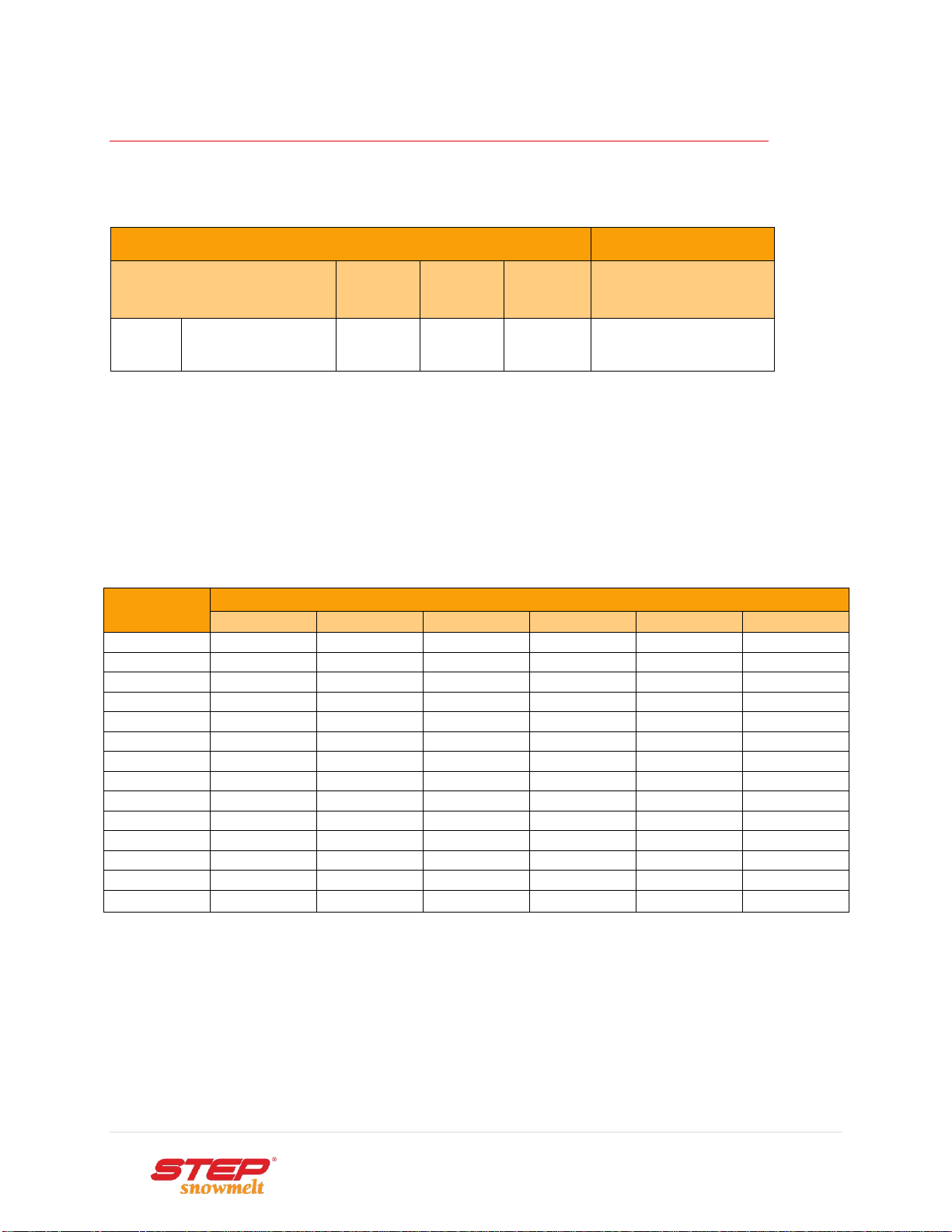
ELEMENT TYPE AND WATTAGE
ELEMENT DATA at 24 VOLTS @ 32oF
INSTALLATION DATA
Element Type
Ohms
Linear
Density
Max. length @ 450W
Width
Model
/ft.
W/ft.
W/sqft.
feet
12”
MEP-30-70W
24
24
24
18
9”
MEP-23-80W
21
27
36
16
Table: Element type and wattage
WIRE GAUGE AND LENGTH
Minimize voltage drop by planning the wire runs as short as possible. Use larger wire gauge for
more power output.
Refer to the following chart for maximum secondary wire length, both wires included, per circuit
in feet.
Power Watts
Wire Gauge and Wire Length in Feet
14 AWG
12 AWG
10 AWG
8 AWG
6 AWG
4 AWG
60 VA
40
63
100
159
252
401
90 VA
27
42
67
106
168
268
120 VA
20
32
50
80
126
201
150 VA
16
26
40
64
101
161
180 VA
14
21
34
53
84
134
210 VA
12
18
29
46
72
115
240 VA
10
16
25
40
63
101
270 VA
9
14
23
36
56
90
300 VA
8
13
20
32
51
81
330 VA
8
12
19
29
46
73
360 VA
7
11
17
27
42
67
390 VA
7
10
16
25
39
62
420 VA
6
9
15
23
36
58
450 VA
6
9
14
22
34
54
To simplify distribution to the elements use a terminal block when you have multiple elements.
Keep each terminal block to maximum 450W and then calculate the appropriate wire size used to
run to the power supply.
Refer to the Wire Gauge and Length Calculator on www.warmfloor.com.
8 | P a g e
Copyright ©Electro Plastics, Inc. / STEP Warmfloor®September 2015
PRODUCT SPECIFICATIONS
CONSTRUCTION
The STEP®Snowmelt heating elements MEP-30-70W and MEP-23-80W are designed to prevent
ice and snow on walkways and driveways. The element is constructed of two parallel bus braids
embedded in semi-conductive PTC polymer.
A polymeric dielectric liner is applied at the time of manufacturing so that the liner is thermally
fused to the heating element. This creates a heating element that features a solid and
homogeneous construction which is chemically inert.
The 12” and 9” wide elements normally come slotted, unless specified with no slots.
APPLICATION
Snow and Ice Prevention
System
Suitable for ice and snow prevention on concrete, stone or
asphalt walkways and driveways, commercial and residential.
The element is not made to be exposed to weather.
MEP-30-70W
MEP-23-80W
Amperage draw @ 32°F (0°C), 24V 1 A
1,125 A
Nominal resistance @ 32°F (0°C) 24 Ω
21 Ω
Maximum continuous element length: 18 ft. (5.5 m)
16 ft. (4.9 m)
Bus Braids
Tinned Copper
Semi-Conductive Core
Self-Regulating
Dielectric Insulation
Polyethylene Film
Slots
Increase Flexibility

9 | P a g e
Copyright ©Electro Plastics, Inc. / STEP Warmfloor®September 2015
PRODUCT SPECIFICATIONS
HEATING ELEMENT MODELS
Heating element type
Positive Temperature Coefficient (PTC) semi-conductive
polyethylene
Dimensions
Width: Weight:
MEP-30-70W-24V: 12” (30 cm) 0.21 lb/ft (0.32 kg/m)
MEP-23-80W-24V: 9” (23 cm) 0.17 lb/ft (0.25 kg/m)
Thickness: 3/64” (1.2 mm)
Length: cut to order with a standard spool length of 174ft (53m)
Output wattage
(see power output curve)
70W »24 W/ft (78.7 W/m) @ 32oF (0oC)
80W »27 W/ft (88.6 W/m) @ 32oF (0oC)
Watt density:
MEP-30-70W-24V: 24 W/ft2(258 W/m2) @ 32°F (0°C)
MEP-23-80W-24V: 36 W/ft2(387 W/m2) @ 32°F (0°C)
Supply voltage
24V AC or DC
Bus braid
15 AWG tinned copper flat braid
Dielectric liner
Thermally bonded to heating element
Minimum bending radius
3/32” (2.5mm) @ 40°F (4°C)
Maximum exposure temperature
176°F (80°C)
Minimum exposure temperature
-40°F (-40°C)
Chemical Compatibility
The MEP element is resistant to most chemicals and adhesives.
POWER OUTPUT CURVE

10 | P a g e
Copyright ©Electro Plastics, Inc. / STEP Warmfloor®September 2015
INSTALLATION
1. PLAN
Design system, and make a layout. For guidance, see attached layout and wiring
diagram.
When deciding on a snowmelt system it is essential to decide on the purpose of the
system and how effective the system should be. Should the ground be completely dry
or is it acceptable with some snow slush on the ground shortly after a snowfall.
ASHRAE classifications split snowmelt systems into three groups:
oSnow free ratio 0:
Designed not to melt snow while it is falling, but
afterwards.
oSnow free ratio 0.5:
50% of snow is melted while falling, the rest afterwards.
oSnow free ratio 1:
All snow and ice is melted while falling.
When designing a snowmelt system it is essential to know the area conditions;
snowfall days, temperature, surface type, heat loss to ground, atmospheric loss and
perimeter insulations. These are some of the parameters needed to create snowmelt
solutions according to expectations.
An on demand deicing system may be favorable in places with few snowfall days.
Areas with frequent snowfall may benefit from the thermal bed concept which is a low
power deicing system that is switched on prior to frost and kept energized all winter.
Wherever underlying soils are susceptible to frost, pavements will suffer damaging
effects from frost heave and spring breakup. There are different techniques to reduce
frost action, such as:
oRemoving frost-susceptible soil and using thick base courses to spread the load
during spring thaw.
oProviding adequate drainage for free water through ditching.
oPlacing a layer of insulation in the embankment section to keep sub-grade soil
temperatures above freezing. Maintaining the soil above freezing temperatures by
placing heating elements in the upper soil or pavement section.
Installation should conform to local building codes, ordinances, and trade practices.
2. INSTALL
Heating elements should be installed in ambient temperatures between 40oF and
140oF (4oC and 60oC).
Lay the STEP®elements onto an even layer of granular material and secure them in
place to prevent displacement of panels.
Avoid heating elements to overlap or touch each other. DO NOT puncture the bus
braids.
Apply subsequent lifts, pavement or soil layers taking care not to damage the heating
elements.

11 | P a g e
Copyright ©Electro Plastics, Inc. / STEP Warmfloor®September 2015
INSTALLATION
3. CONNECT
Connect extension wires to the heating element according to the drawing and electrical
diagram. If fail safe wiring is required, refer to instructions in the diagram “Fail Safe
Wiring”.
Determine wire gauge versus load and length of wire from the element to the power
supply. The wire gauge for a circuit fully loaded is 10 AWG by default but if the
distance is longer than 14 feet, connect the extension wires to a terminal block and
then route to the power supply using higher gauge wires as shown in Wiring Diagram.
Insure that wiring is done according to the National Electrical Code.
Route the wires through the ground in a conduit. Connect wires in parallel to the 24
volt AC power supply or DC controller. Use only stranded tinned copper wires, and do
not twist wire ends when connecting to the interface board in the supply.
Distribute the load evenly; the maximum load per circuit is 450 watts.
The power supply must be installed in a well-ventilated area and wired in accordance
with the NEC.Place the power supply vertically using rubber bumpers between the
back heat sink plate and wall for better cooling and quiet operation.
Connect the line voltage to a two-pole on/off switch. Use stranded wires from the
switch to the power supply.
To make the system operational, connect the three signal wires COM, TRG and ~24V
from the interface board terminals to the thermostat. The system will switch on when
the thermostat asks for heat.
The heating elements must be measured and the amp draw noted by a certified
electrician before being covered. The warning label must be placed in the service panel
and the caution label on the electrical box, or on the low-voltage power supply.
NOTE: This system is low voltage and the heating elements must NOT be grounded.
4. COVER
The heating elements should be placed on top of gravel and compacted sand. Then
secured in a way that the elements do not shift position when concrete is poured.
If a reinforcement mesh is used, take care that the no conductive material is in direct
contact with the heating elements.
Do not pour more than 8 inches of concrete over the heating elements. If more is
needed consult manufacturer or a thermic engineer.
NOTE: These installation guidelines are general in nature. Specific project information is
provided by the distributor.

12 | P a g e
Copyright ©Electro Plastics, Inc. / STEP Warmfloor®September 2015
INSTALLATION
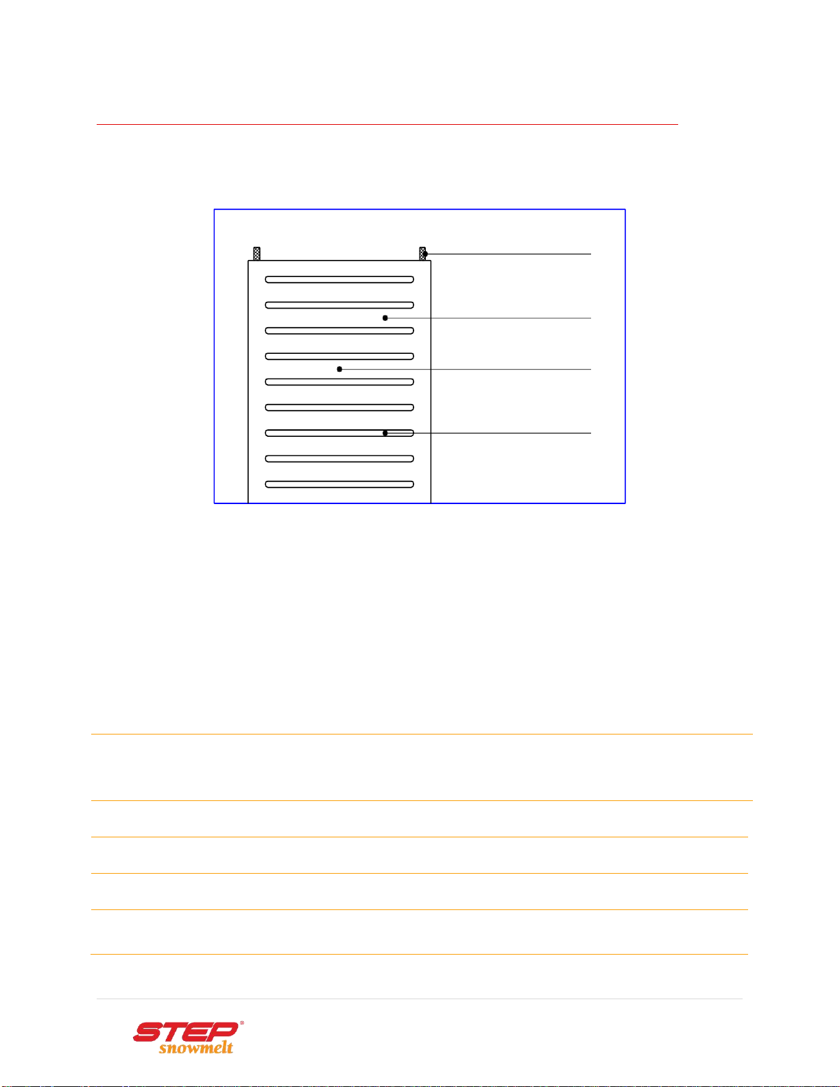
MAKE THE CONNECTIONS
• Make a strain relief connection by
punching three holes with a hand drill
or punch tool. Weave a stranded
tinned copper extension wire in the
holes. Strip the wire end, and join the
wire with the bus braid in the STEP®
tinned copper crimp connector. Crimp
the joint using the required crimp tool.
Using components not recommended
by the manufacturer will void the
warranty.
• Expose the bus braid by making an
angled score in the plastic, front and
back, and along the bus braid above
the angled score with a utility knife.
Bend the element where the cuts are
made and pull offthe corners to
remove the surplus of plastic. Make
sure that the bus braid is not cut or
damaged. Should this occur, re-cut
the element and re-strip the bus braid.
Repeat on the other side.
• Seal all connections by using the
required sealant tape on the connector
side of the element. Cut two pieces of
tape slightly longer than the width of
the element. Enclose the wire joints
and strain relief connections with the
two pieces of tape and firmly press the
pieces together while overlapping the
element to form a flat and smooth
splice. If the opposite end is not
connected use the same vulcanizing
tape to seal the open end of the
element.
13 | P a g e
Copyright ©Electro Plastics, Inc. / STEP Warmfloor®September 2015
INSTALLATION
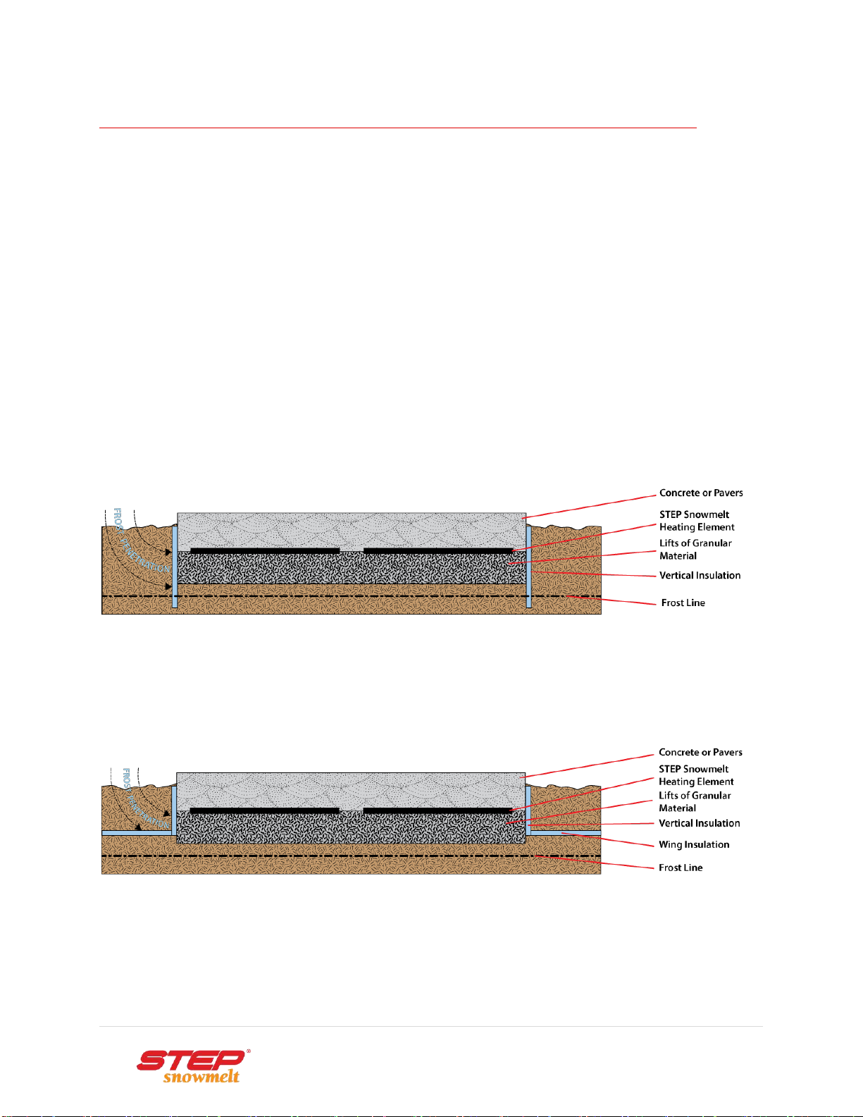
SYSTEM DESIGN
STEP®Thermal Bed system is designed for continuous duty on 24 volts and will melt ice or snow
provided the substrate has been continuously heated. This maintenance heat keeps the ground
temperature constant and reduces the expansion and contraction in substrates.
Place a low water absorption and high compressive strength insulation, e.g.
“Styrofoam*Hi” or equivalent, vertical along the walls of a trench or foundation to
protect against frost penetration.
Care should be taken to prevent vehicles and heavy equipment from bearing directly
on the vertical insulation.
Make sure that the insulation is properly butted together to avoid the transfer of heat
/ cold migration and transfer of moisture.
Thermal Bed Concept
Thermal Bed with Wing Insulation

14 | P a g e
Copyright ©Electro Plastics, Inc. / STEP Warmfloor®September 2015
ELECTRICAL GUIDELINES
LOW VOLTAGE ELECTRIC RADIANT HEATING EQUIPMENT
1. Scope. This installation instruction covers electric radiant heating equipment and associated
components operating at <=30 volts rms or 42 volts peak, or direct current <=60 volts.
2. Low Voltage Heating Equipment.
(A) General. A low voltage heating system shall consist of a low voltage isolating power
supply, heating elements, and associated components that are all identified for the use.
The output circuits of the power supply are rated for 25 amperes maximum and operate
at 30 volts (42.4 volts peak) ac maximum or 60 volts dc maximum under all load
conditions.
(B) Class 2. Listed Class 2 equipment shall be rated in conformance with Chapter 9, Table
11(A) or Table 11(B).
(C) Alternate Energy Sources. Listed low voltage heating equipment shall be permitted to
be supplied directly from an alternate energy source such as solar photovoltaic (PV) or
wind power. When supplied from such a source, the source and any power conversion
equipment between the source and the heating equipment and its supply, shall be listed
and comply with the applicable section of the NEC for the source used.
3. Listing Required. Low voltage heating systems shall comply with (A) and (B).
(A) Listed System. Low voltage heating systems shall be listed as a complete system. The
heating portion of the product, power supply, interconnecting wiring, and fittings shall be
listed for the use as part of the same identified heating system.
(B) Assembly of Listed Parts. The listed system and approved system components shall be
installed in accordance with the low voltage heating product manufacturer’s instructions.
4. Low Voltage Circuits.
(A) Ground. Secondary circuits shall not be grounded.
(B) Isolation. The secondary circuit shall be insulated from the branch circuit by an isolating
transformer, provided as part of the listed assembly.
5. Provisions.
(A) Fixed Electric Space Heating Equipment. Installation shall be made in accordance
with NEC 424, Chapter V, Electric Space Heating Cables, or Chapter IX, Electric Radiant
Heating Panels and heating Panel Sets, except as noted in 424.100-424.102.
(B) Fixed Outdoor Electric Deicing and Snow Melting Equipment. Installation shall be
made in accordance with NEC Article 426, except as noted in 424.100-424.102.

15 | P a g e
Copyright ©Electro Plastics, Inc. / STEP Warmfloor®September 2015
AC POWER SUPPLY WIRING DIAGRAM
16 | P a g e
Copyright ©Electro Plastics, Inc. / STEP Warmfloor®September 2015
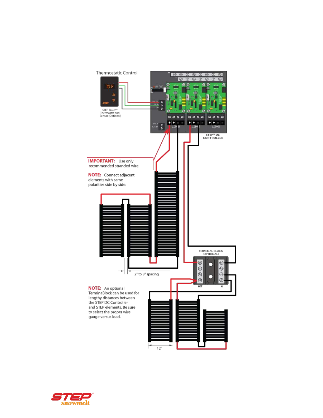
DC CONTROLLER WIRING DIAGRAM
17 | P a g e
Copyright ©Electro Plastics, Inc. / STEP Warmfloor®September 2015
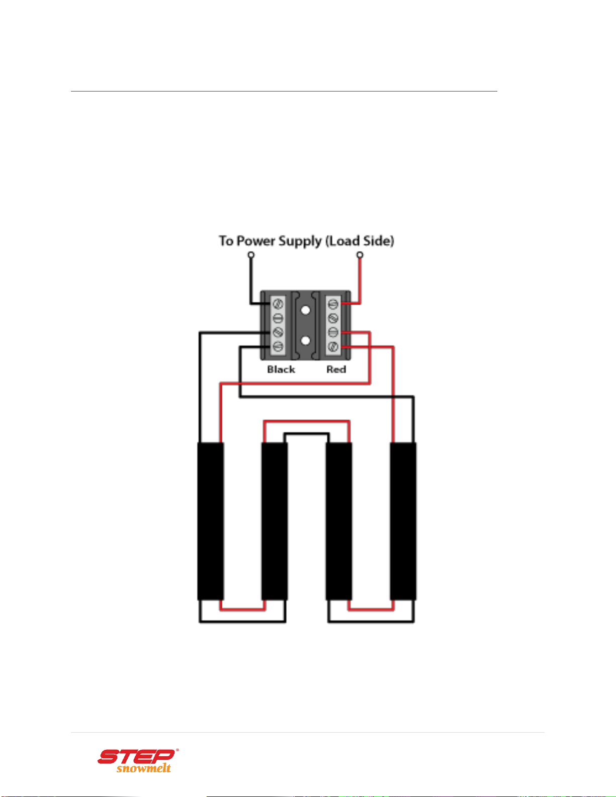
FAIL SAFE WIRING
• The Fail Safe Wiring method is used whenever there may be a risk of damaging the bus braids
located on each side of the heating elements.
• Supplying electricity from both ends of an element eliminates the possibility of arcing from a
damaged bus braid.
• Not only is this wiring method safer, it reduces voltage drop and makes the element more powerful.

18 | P a g e
Copyright ©Electro Plastics, Inc. / STEP Warmfloor®September 2015
CONTROLS
STEP TOUCH® THEMOSTAT
SPECIFICATIONS
THERMOSTAT
The STEP Touch®thermostat can be used in conjunction with all the EPI-LX-R power supply
series and the STEP DC Controllers
Install the thermostat indoors.
Measure the distance from the power supply to the thermostat to identify the length of
the thermostat wire.
The low-voltage (24V) thermostat is connected to the power supply using a 3-conductor cable
and can control unlimited power supplies.
EXTENAL SENSOR
The external temperature sensor is installed in the concrete, in a conduit, between the heating
elements.
SETTINGS
Set dip-switches in the back to snowmelt mode:
Pos.1 (C°) or F°: ►displays Celsius or Fahrenheit
Pos.2 or DIM: ►display is lit or dimmed
Pos.3 to EXT: ►displays the external temperature when an exterior
temperature sensor is attached.
Pos.4 to SM: ►snowmelt with remote external temperature sensor
FUNCTION
The STEP®Touch thermostat collects temperature information every 1.5 second for 10 minutes
before deciding to add or reduce heat. This cycle is repeated endlessly.
OPERATION
When the settings are done the thermostat is operated by two touch buttons only; up or down or
press both buttons simultaneously to switch the system off.

19 | P a g e
Copyright ©Electro Plastics, Inc. / STEP Warmfloor®September 2015
WARRANTY REGISTRATION AND COVERAGE
LIMITED WARRANTY
Electro Plastics’ limited warranty is valid from date of original purchase, as follows (not included in this
warranty are OEM and specialty products):
20 years for the STEP Warmfloor®Heating Elements.
10 years for the STEP®Snowmelt and Deicing Heating Elements.
10 years for the STEP®Transformer Coils in the Power Supplies.
3 years for the Interface Electronics in the Power Supplies.
3 years for the STEP®Controls
Electro Plastics sole obligation under its warranty shall be, at its option, to either issue a credit for the
purchase price, or repair or replace any article or part thereof, which is proved to be other than as
warranted. For this warranty to be valid, a copy of the STEP®Labels shall be delivered to ELECTRO
PLASTICS, INC., with a diagram indicating to which branch circuit the system is connected, the
location of the element strips, the routing of the wires and their different measurements, voltage,
amperage, elements and wire length. Electro Plastics warrants the products to be free from defects in
material or manufacturing and to perform under normal use. For the warranty to be valid, qualified
personnel who are familiar with the construction and operation of the system must install the
equipment and a certified electrician has to verify and measure the STEP®elements BEFORE they are
covered.
Exclusions
Electro Plastics shall not be responsible for any loss or damage that may arise due to:
Non-compliance with installation and/or usage of the STEP®elements and accessories as
recommended. It shall be Buyer’s and End User’s duty to read and follow carefully the STEP®
Installation Manual. Technical assistance services, e.g. design and layout are to be used as
GUIDELINES ONLY, as each application is specific to local conditions and construction
Dissatisfaction due to improper Installation of the floor covering. All floor covering shall be
installed in conformance with the manufacturer’s instructions and shall conform to all
applicable trade practices, local codes and manufacturer's specifications.
Usage of inadequate or non-specified materials with the STEP®heating system or products.
Any and all defects, deficiencies or failures resulting from improper handling of the product;
e.g., cuts made to the STEP®elements, or the wires, etc.
Tampering with the STEP®heating system or products; e.g., removing, altering or overloading
the circuit breakers, overcurrent protectors, etc.
Installation of merchandise with obvious visible defects.
How to claim this warranty
In order to obtain warranty service, Buyer shall return the unit to the dealer from whom the unit was
originally purchased, with a dated sales receipt. The dealer will forward the unit to Electro
Plastics. Upon receipt of the defective unit, paperwork and explanation of application, Electro Plastics
will inspect and test the unit in order to determine the reason for the alleged failure. If it is
determined that the unit was properly installed and failed during normal use, as a result of a
manufacturing defect, Electro Plastic will repair or replace the unit, or issue a credit or refund of the
purchase price, at its sole discretion. The warranty period for any replacement unit will fulfill the
warranty of the original unit and will not be extended.

20 | P a g e
Copyright ©Electro Plastics, Inc. / STEP Warmfloor®September 2015
WARRANTY REGISTRATION AND COVERAGE
Limitations
Under no circumstances will Electro Plastics be liable for labor or other charges related to the
installation and use of the STEP®heating system or products. This warranty does not cover labor or
removal or reinstallation of the product and is void on any product installed improperly, or in an
improper environment, overloaded, misused, abused or altered in any manner. THE WARRANTIES
STATED HEREIN ARE EXCLUSIVE OF ALL OTHER WARRANTIES, WRITTEN OR ORAL, STATUTORY
EXPRESS OR IMPLIED, INCLUDING ANY WARRANTIES OF MERCHANTABILITY AND FITNESS FOR A
PARTICULAR PURPOSE, NONE OF WHICH SHALL APPLY TO THE SALE OF THE COMPANY'S PRODUCTS
HEREUNDER. THIS WARRANTY ALSO EXCLUDES INCIDENTAL OR CONSEQUENTIAL DAMAGES FOR
BREACH OF ANY WARRANTY ON THE PRODUCTS. Products which are replaced by Electro Plastics in
accordance with the foregoing shall become the property of Electro Plastics and shall be returned to it
by the purchaser f.o.b. point of shipment. The maximum liability of this warranty is limited to the
replacement or repair or purchase price of the defective unit. If a unit is returned and found that no
defect exists, or that the user misused the unit, Electro Plastics will inform the user. If the user
chooses to have the unit repaired (if possible), labor and shipping charges will apply.
Limitation of Liability
ELECTRO PLASTICS SHALL NOT BE LIABLE FOR ANY LOSS, CLAIM, EXPENSE OR DAMAGE CAUSED BY,
CONTRIBUTED TO OR ARISING OUT OF THE ACTS OR OMISSIONS OF BUYER OR THIRD
PARTIES, WHETHER NEGLIGENT OR OTHERWISE, IN NO EVENT SHALL ELECTRO PLASTICS' LIABILITY
FOR ANY CAUSE OF ACTION WHATSOEVER EXCEED THE COST OF THE PRODUCT GIVING RISE TO
THE CLAIM, WHETHER BASED IN CONTRACT, WARRANTY, INDEMNITY OR TORT (INCLUDING
NEGLIGENCE AND STRICT LIABILITY) OR OTHERWISE. IN NO EVENT SHALL ELECTRO PLASTICS BE
LIABLE OR ANY SPECIAL, INCIDENTAL, CONSEQUENTIAL OR OTHER SUCH INDIRECT
DAMAGES (INCLUDING, WITH-OUT LIMITATION, LOSS OF REVENUES, PROFITS OR OPPORTUNITIES),
WHETHER ARISING OUT OF OR AS A RESULT OF BREACH OF CONTRACT, WARRANTY,
TORT (INCLUDING NEGLIGENCE), STRICT LIABILITY OR OTHERWISE
WARRANTY REGISTRATION CARD
Ref. No. ...............................
CUSTOMER INFORMATION
PURCHASE AND PROJECT INFORMATION
_________________________________________
Owner’s Name
__________________________________ ___________
Purchased From Date
_________________________________________
Address
______________________________________________
Address
_________________________________________
City / State / Zip
Product Purchased:
Snowmelt
Deicing
_________________________________________
Phone
Heating Elements
Installed on :
Deck / Ramp
Driveway
Pathway
_________________________________________
Email
Heating Elements
Installed under:
Concrete
Stone
Other
Type of Project:
New Construction
Renovation Project
To activate warranty complete and return this warranty registration card signed with a complete checklist and
layout showing element distribution as installed to: 11147 Dorsett Road, Maryland Heights, MO 63043, U.S.A.
Table of contents
Popular Outdoor Furnishing manuals by other brands


Greemotion
Greemotion Cyprus GM-2006 quick start guide

tepro
tepro KAEMI instruction manual

Arbor Technology
Arbor Technology Alders Picnic Table and Bench set Assembly instructions

Sojag
Sojag Verona Assembly manual

Santa & Cole Urbidermis
Santa & Cole Urbidermis ANTONI ROSELLO MAYA quick start guide

Stratco
Stratco Outback Flat Attached installation guide

Big Lots
Big Lots Willow Point DE21343 Assembly and Care Guide

Belleze
Belleze 014-HG-17033 manual

TREEPOD
TREEPOD HITCH MOUNT instruction manual

BARKER AND STONEHOUSE
BARKER AND STONEHOUSE TENBY T3NBDINIGREY Assembly instructions

Sunjoy
Sunjoy L-GZ407PST-KD Assembly instructions

SUNVILLA
SUNVILLA 1902439 Assembly / care & use instructions