Sterling SHA4 User manual

OWNER’S MANUAL

2
SHA4 4-CHANNEL HEADPHONE AMP
TABLE OF CONTENTS
Introduction ............................... 2
Features ................................. 2
Unpacking ................................ 2
Important Safety Instructions................ 2-3
Application Guidelines....................... 3
Controls and Connections .................... 4
Functional Description....................... 5
Rear Connections .......................... 5
Front Controls ............................. 5
Connections............................... 6
Operation................................. 7
Technical Specifications ..................... 7
Warranty ................................. 8
INTRODUCTION
Congratulations on the purchase of your Sterling SHA4
Headphone Amplifier, a 4-way headphone amplifier
with 4 high-power headphone amplifiers assignable
to 2 individual inputs. Dual front/rear connections,
integrated microphone stand adapter, and an internal
wide-range power supply make this unit suitable for a
large variety of applications in recording, live sound
and installation environments.
FEATURES
• 4 Channels — with 8 total headphone outputs (2
per channel)
• Individual switchable input monitoring (A or B)
• Stereo ¼” TRS and 3.5mm mini connector (TRS)
headphone outputs
• Balanced ¼” (TRS) line level and unbalanced ¼”
(TS) line level inputs
• Stereo ¼” TRS ‘Link’ connectors for daisy chaining
and/or external processing
• Integrated mic stand mount for flexible integration
in both studio and home recording
• Integrated internal power supply eliminates
obstructive wall-worts
UNPACKING
Please check that the box contains the following items:
1 pc. SHA4 main unit
1 pc. AC Power cable
1 pc. Operation manual
If any part is missing, please contact your dealer
immediately for replacement
WARNING
After unpacking, and before plugging the AC cord in
the wall outlet, check whether the AC mains voltage
and frequency is the same as this product is specified
for (see rear panel of product). Whenever the specified
voltage or your AC plug should not match the local
conditions, do NOT plug the AC cord into the wall
outlet and contact your dealer immediately.

3SHA4 4-CHANNEL HEADPHONE AMP
device shall remain readily operable.
PROTECTIVE GROUND TERMINAL
The apparatus shall be connected to an AC main
socket with a protective earth ground connection.
ELECTROMAGNETIC RADIATION
This unit produces and absorbs electromagnetic
radiation. The strength of radiation and the sensitivity
for disturbing interference matches FCC requirements.
Any change or modification may affect the behavior of
the unit concerning electromagnetic radiation, with the
FCC requirements eventually not to be met any more.
The manufacturer takes no responsibility in this case.
This unit is immune to the presence of electromagnetic
disturbances — both conducted and radiated — up
to a certain level. Under peak conditions, the unit is
classified to show a “Class C” performance criteria
and may encounter temporary degradation or loss of
function which may need manual help to recover. In
such case, disconnect the AC power from the unit and
reconnect it again to recover.
WARNING – VOLUME LEVELS
Excessive volume levels on headphones or other
sound systems may cause hearing damage. Always
turn the volume control to minimum when you switch
the unit on, and avoid prolonged exposure to sound
pressure levels exceeding 85dB.
ROHS Standards
This unit is built to conform to the ROHS standards.
Consult with your local governments electronic waste
recycling programs before disposing of this unit for
end-of-life disposal.
APPLICATION GUIDELINES
USING THE MAIN INPUT CONNECTORS
Connect a program source with the MAIN INPUT
connectors located on the rear, and connect your
headphones to a channel section of your choice, #1
through #4. The knobs for INPUT A and B control
the level of each separate input signal. The individual
output knobs are used for adjusting the desired channel
volume to headphones only.
IMPORTANT SAFETY INSTRUCTIONS
• Keep & read these instructions.
• Heed all warnings & follow all instructions.
• Do not use this apparatus near water.
• Clean only with dry cloth.
• Do not block any ventilation openings. Install in
accordance with the manufacturer’s instructions.
• Do not install near any heat sources such as
radiators, heat registers, stoves, or other apparatus
(including amplifiers) that produce heat.
• Do not defeat the safety purpose of the polarized
or grounding-type plug. A polarized plug has two
blades with one wider than the other. A grounding-
type plug has two blades and a third grounding
prong. The wide blade or the third prong are
provided for your safety. If the provided plug does
not t into your outlet, consult an electrician for
replacement of the obsolete outlet.
• Protect the power cord from being walked on
or pinched particularly at plugs, convenience
receptacles, and the point where they exit from the
apparatus.
• Only use the attachments/accessories specified
by the manufacturer.
• Unplug this apparatus when unused for long
periods of time.
Refer all servicing to qualified service personnel.
Servicing is required when the apparatus has
been damaged in any way, such as power-supply
cable or plug is damaged, liquid has been spilled
or objects have fallen into the apparatus, the
apparatus has been exposed to rain or moisture,
does not operate normally, or has been dropped.
• Refer all servicing to a qualified service professional.
Servicing is required when the apparatus does not
operate normally or has been damaged in any
way, including damage to the power cable or plug,
damage due to liquids spilled or objects dropped
inside the unit, dropping the unit, or anything else
that interrupts normal use of the unit.
WARNING: To reduce the risk of electric shock, do not
expose this apparatus to rain or moisture.
When the MAINS power cable, or an appliance coupler
is used as the disconnect device, the disconnect
4
SHA4 4-CHANNEL HEADPHONE AMP
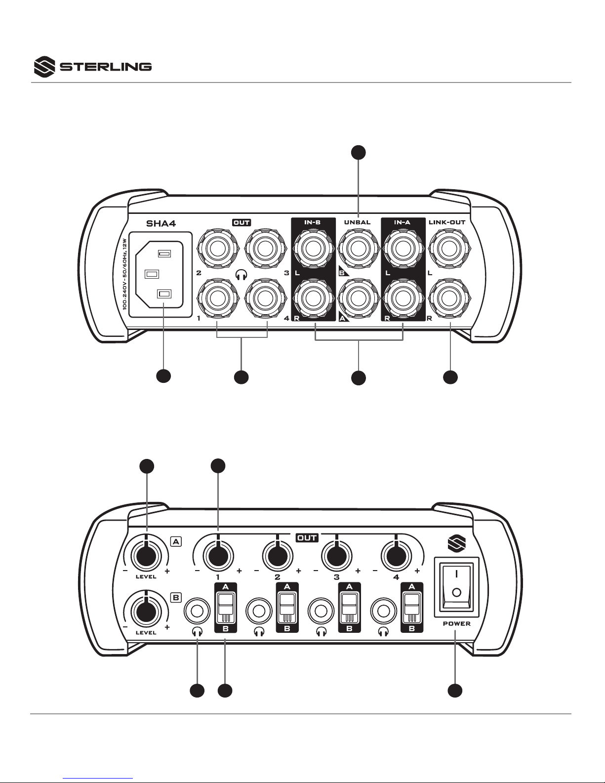
CONTROLS AND CONNECTIONS
CONTROLS - FRONT
7 8 10
69
12 5
3
4
CONTROLS AND CONNECTIONS
CONNECTIONS - REAR
5SHA4 4-CHANNEL HEADPHONE AMP
REAR CONNECTIONS
1AC POWER INLET
Use the supplied AC power cord to connect the unit
to AC socket. Make sure voltage and frequency
stated and set on the unit comply with your local
AC supply.
2HEADPHONE REAR OUTPUTS (Channels 1 - 4)
These are stereo (TRS) outputs suitable to drive
headphones.While headphones down to 32 Ohms
can be connected, a higher impedance type (>60
Ohms) is recommended for lower distortion at
high output levels. These outputs are in parallel
to the front panel outputs ( 7). Note that in case
headphones are connected to both front and
rear outputs, the load impedance will only be
half, so headphones must have a sufficiently
high impedance.
3MAIN INPUTS (BALANCED) L and R
(Inputs A and B)
These are balanced TRS connectors. The L input
shall be used when the source is mono, or shall
be used as the left channel input when the source
is stereo. The R input shall be used for the right
channel of stereo sources. Left and Right input
respectively is marked on the lower left corner
near the connector.
4MAIN INPUTS (UNBALANCED) STEREO
(Inputs A and B)
These are unbalanced 1/4” TRS input connectors
that provide left and right audio input signals. This
input shall not be used when the source is mono.
5LINK OUTPUT (INPUT A ONLY)
This is a pair of 1/4” balanced TRS output
connectors, that will output the signal provided
to audio INPUT “A” only. This can be used to
daisy chain multiple SHA4 units or send audio
input “A” signal to another piece of electronics
processing gear.
FRONT CONTROLS
6INPUT LEVEL CONTROLS (Inputs A and B)
Adjusts the input level of the signal connected via
the connectors ( 3) or ( 4).
7HEADPHONE FRONT OUTPUTS (Channel 1 - 4)
These are stereo 3.5mm (Mini-TRS) outputs
suitable to drive headphones. While headphones
down to 32 Ohms can be connected, a higher
impedance type (>60 Ohms) is recommended
for lower distortion at high output levels. These
outputs are in parallel to the rear panel outputs
(2). Note that in case headphones are connected
to both front and rear outputs, the load impedance
will only be half, so headphones must have a
sufficiently high impedance.
8SOURCE SELECTOR SWITCHES (Channels 1 - 4)
These switches determine whether the relative
output channel plays the signal of input “A” or
input “B”.
9OUTPUT LEVEL CONTROL (Outputs 1 - 4)
These controls set the outputs levels individually
for the relative headphone output ( 2) and ( 7).
10 POWER SWITCH
Switches the unit on and off. Make sure to switch
the unit off when not in use. When powered “on”,
the switch will illuminate.
6
SHA4 4-CHANNEL HEADPHONE AMP
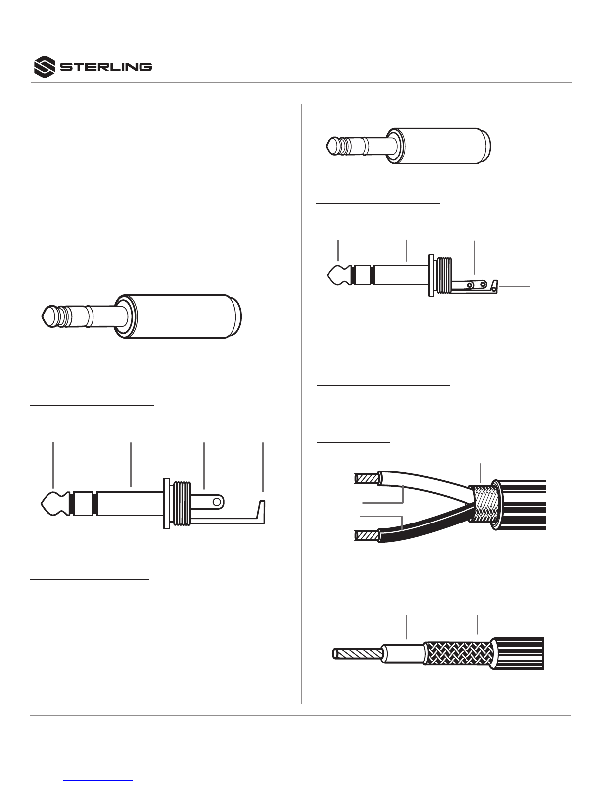
CONNECTIONS
The SHA4 uses the below connector types, for
which the pin assignment must comply with the
following specifications. Always make sure to use
good connectors and cables to ensure proper
operation. Balanced connections are to be preferred
over unbalanced connections where applicable and
feasible. Avoid unbalanced connections exceeding 2m
of cable length.
1/4”MM TRS-MONO TIP
3.5”MM TRS-STERIO TIP
CABLE TYPES
BALANCED CONNECTION
Red = Tip
Black = Sleeve
Shield = Uncon.
UNBALANCED CONNECTION
Red = Tip
Shield = Sleeve
BALANCED CONNECTION
Red = Tip
Black = Ring
Shield = Sleeve
UNBALANCED CONNECTION
Red = Tip
Shield = Sleeve+Ring
CABLE TIP STRUCTURE
CABLE TIP STRUCTURE
Tip Tip
Sleeve
1-conductor shielded cable
(for balanced connections)
ShieldRed
2-conductor shielded cable
(for balanced connections)
Red
Shield
Black
Tip TipSleeve Sleeve
Sleeve

7SHA4 4-CHANNEL HEADPHONE AMP
OPERATION
A. CONNECTIONS
For connecting this unit to AC mains, please note:
Check whether the AC mains voltage and frequency
is the same as this product is specified for (see rear
panel of product). Whenever the specified voltage or
your AC plug should not match the local conditions, do
NOT plug the AC cable into the wall outlet and contact
your Sterling Audio retailer immediately.
Do not operate this unit without the power cable earth
ground connected. To do so may increase the risk
of electric shock and increase line cable conducted
emissions.
For making audio signal connections, always
remember that good and reliable connections are
a basic requirement for good sound and reliable
operation. Bad soldering of cables can result in
intermittent audio signals or temporarily lost ground
connections, hence always use good cables. In case
of doubt about making proper connections, please
see check the standard pin assignments required for
proper operation in the following section of this manual.
B. POWERING UP
Following a proper power-up sequence protects your
equipment – specifically speakers – and your ears.
Follow the below procedure:
• Turn down all output volume controls of any
equipment in your audio system.
• Switch on your audio source(s) first.
• Switch on the audio mixer Switch on any audio
processor between the mixer and the amplifier(s)
Tuners, CD Players, PC’s with soundcards,
Tapedecks, etc.).
• Switch on the audio mixer.
• Switch on any audio processor between the mixer
and the amplifier(s) [if any].
• Switch on the amplifier(s).
• Turn up the audio level on your sources if such
controls are provided.
• Set the audio output of your mixer to a low level.
• Set the audio output of any audio processor
between the mixer and the amplifier(s) to a
medium level [if any such processors].
• Turn up the volume controls of your amplifier(s)
slowly.
• Make adjustments to all volume settings as
needed.
• For switching o, follow the inverse sequence –
always switch on your amplifier (s) first, then any
processors between mixer and amplifier (s), then
the mixer, then the sources.
C. USE
Apart from using good equipment, good sound comes
from using it correctly. Level setting mistakes are one
of the common reasons why even good equipment
may not perform as desired. For setting levels, please
be reminded that two guidelines need to be followed:
• Avoid distortion by leaving some headroom. Never
overrun any audio-equipment’s inputs. Level
meters and displays allow you to make sure that
signals do not enter critical levels.
• Avoid unnecessary amplification by using as little
gain as possible. For example, if you turn down
the input gain of a mixer to minimum, and then
increase the main output of the mixer to maximum
to drive your amplifier properly, you will create
unnecessary noise, as you first dispose of some
already existing signal level, and then later apply
amplification (tainted with noise) to make it up.
Obviously, these two requirements are marking a
leveling window that the operator must match to
achieve a good sound with as little distortion and noise
as possible.
TECHNICAL SPECIFICATIONS
Max Output Power
Per Channel: .....+21dBm (load impedance 100 Ω)
Signal/Noise: ....>90dBu (unweighted 22Hz-22KHz)
THD: .......................... <0.01% (Line)
Frequency Response: .............20Hz – 20KHz
AC Input: ..................100/240V ~ 50/60Hz
Power Consumption: ............. 12W, maximum
Dimensions:...........W: 6.2” x H: 1.92”x D: 5.17”
Weight ..............................1.43 lbs.

8
SHA4 4-CHANNEL HEADPHONE AMP
2 YEAR LIMITED WARRANTY
Subject to the limitations set forth below, Sterling
Audio® hereby represents and warrants that the
components of this product shall be free from defects
in materials and workmanship, including implied
warranties of merchantability or fitness for a particular
purpose, subject to normal use and service, for 2 years
to the original owner from the date of purchase, (proof
of purchase required).
Retailer and manufacturer shall not be liable for
damages based upon inconvenience, loss of use
of product, loss of time, interrupted operation
or commercial loss or any other incidental or
consequential damages including but not limited to lost
profits, downtime, goodwill, damage to or replacement
of equipment and property, and any costs of recovering,
reprogramming, or reproducing any program or data
stored in equipment that is used with Sterling Audio®
products.This guarantee gives you specific legal rights.
You may have other legal rights which vary from state
to state. Some states do not allow limitations on how
long an implied warranty lasts, so the above limitation
may not apply to you.
Sterling Audio
P.O. Box 5111, Thousand Oaks, CA 91359-5111
sterlingaudio.net
All trademarks and registered trademarks mentioned herein are
recognized as the property of their respective holders.
1802-17247629
Table of contents
Other Sterling Amplifier manuals


