STERO SD3 Series Building instructions

SD3 Series
SD3 ML-130232
SERVICE and PARTS
MANUAL
F45576 (1015)

TABLE OF CONTENTS
GENERAL .................................................................................................. 3
INTRODUCTION ....................................................................................... 3
MODELS COVERED ................................................................................... 3
SPECIFICATIONS ...................................................................................... 3
REFERENCE MATERIAL ............................................................................... 4
POWER-UP ............................................................................................ 4
FILL CYCLE ............................................................................................ 4
BOOSTER TEMPERATURE CONTROL ................................................................ 4
BOOSTER TEMPERATURE CONTROL ............................................................ 4
READY MODE ......................................................................................... 5
RUNNING A CYCLE .................................................................................... 5
CHANGING CYCLE TIME .............................................................................. 5
CHANGING CYCLE TIME .......................................................................... 5
LUBRICATION ......................................................................................... 5
TOOLS ................................................................................................. 5
SERVICE PROCEDURES AND ADJUSTMENTS ............................................................ 6
CONTROL BOARD PROGRAMMING ................................................................... 6
SERVICE PROGRAMMING ............................................................................. 7
TANK HEATER - TEST ................................................................................ 10
BOOSTER HEATER - TEST ........................................................................... 11
PUMP MOTOR - TEST ................................................................................ 12
THERMISTOR - TEST 1QTM, 2QTM & 3QTM .......................................................... 12
QUICK CHECK USING SERVICE DIAGNOSTICS .................................................. 12
MEASURING THERMISTOR RESISTANCE ....................................................... 12
TRANSFORMER 1T - TEST ........................................................................... 13
TRANSFORMER 2T - TEST ........................................................................... 14
DELIMIMG PROCEDURE ............................................................................. 15
DOOR TENSION ADJUSTMENT ...................................................................... 15
ELECTRICAL OPERATION ................................................................................ 16
COMPONENT FUNCTION ............................................................................ 16
COMPONENT LOCATION ............................................................................. 17
CONTROL BOARD / RELAY BOARD LAYOUT ........................................................ 18
SEQUENCE OF OPERATION ......................................................................... 19
CONTROL AND RELAY BOARD LEDS ................................................................ 21
WIRING DIAGRAM - 1 PHASE ........................................................................ 23
WIRING DIAGRAM - 3 PHASE ........................................................................ 24
TROUBLESHOOTING ..................................................................................... 25
QUICK REFERENCE CHART - ELECTRIC HEAT ...................................................... 25
CONTROL BOARD AND RELAY BOARD LEDS ................................................... 27
CONTROL BOARD AND RELAY BOARD .............................................................. 27
OPERATING CONDITIONS ....................................................................... 27
NO DISPLAY AFTER ON KEY IS PRESSED ....................................................... 28
NO FILL OR RINSE ............................................................................... 29
LONG FILL TIME (6 MINUTES) .................................................................... 30
NO WASH CYCLE ................................................................................ 30
NO TANK HEAT ................................................................................... 31
SERVICE DIAGNOSTICS ............................................................................. 32
SERVICE DIAGNOSTICS CHART ..................................................................... 33
OUTPUT TESTS ...................................................................................... 34
VERIFY CONTROL BOARD IS CONFIGURED AS AN SD3 ............................................ 35
ERROR CODE CHART ................................................................................ 35
TROUBLESHOOTING TABLE ......................................................................... 35
SD3 Series
F45576 (1015) Page 2 of 37
PARTS CATALOG ............................................................................................................................................. 36
© COMPETITIVE 2015

GENERAL
INTRODUCTION
This manual is applicable to the models and ML
numbers listed on the cover page. Procedures apply
to all models unless specified otherwise.
MODELS COVERED
SD3-H: Single water inlet. Incoming water of 110°F
minimum is heated by a booster tank mounted on the
machine. The machine is configured for a 70°F rise
depending on incoming water temperature. The
booster maintains water temperature to be used for
180°F final rinse.
SD3-P: Single water inlet. Water temperature to
machine must be a minimum of 180°F for the final
rinse. This water is provided by the customer external
of the machine. The SD3-P has the option to be
reprogramed to change from plain to chemical.
SPECIFICATIONS
• Operates as an atmospheric booster (SD3 with
built-in booster).
• Low water protection.
• One incoming plumbing connection to
dishwasher through an electrically operated
valve.
•The fill/rinse valve is installed prior to the 3.6
gallon booster tank.
• Supply flowing water pressure 20 ±5 psi.
• Provides a minimum 70°F rise with incoming
water temperature of 110°F for a final rinse
temperature of 180°F at 20 psi (flowing).
• The dishwasher, with the booster, can operate at
full capacity with back-to-back cycles (SD3).
• SD3 machines are available in several operating
voltages for single or three phase operation.
ELECTRICAL SPECIFICATIONS
Model Electrical Specs Rated Amps
Minimum Supply
Circuit Conductor
Ampacity
Maximum
Overcurrent
Protective Device
SD3 with Electric
Heat
208-240/60/1 43.0 50 50
208-240/60/3 24.9 30 30
480/60/3 13.4 15 15
Booster Ampacity
Ratings 8.5KW
208-240/60/1 35.4 50 50
208-240/60/3 20.4 30 30
480/60/3 10.2 15 15
Optional SD3 Single
Point Electrical
Service Connection
208-240/60/3 45.4 60 60
480/60/3 23.7 30 30
WATER SUPPLY REQUIREMENTS
Model Temperature
(minimum)
Flowing
Pressure
Hardness
grains/gal.1Chlorides ppm Water Usage
SD3 -P (Plain) 140°F 20±5 psi Under 3
1 to 3 ≤ 50 0.74 gal/rack
SD3-H (Hot) 110°F
SD3 Series - GENERAL
Page 3 of 37 F45576 (1015)
WATER SUPPLY REQUIREMENTS
Model Temperature
(minimum)
Flowing
Pressure
Hardness
grains/gal.1Chlorides ppm Water Usage
1 Water hardness below 4 grains/gal requires water treatment to reduce potential corrosion. Hardness
above 6 grains/gal should be treated by water conditioner, water softener or in-line treatment.
MACHINE CYCLE TIMES AND CAPACITY (RACKS / HOUR)
Model Cycle
Settings
Time in Seconds (maximun time settings)
1st 1/2 Fill 2nd 1/2 Fill Wash
Duration1Dwell2Rinse2Sani-Dwell2
All
1
Variable up
to 150
Variable
75-120
38 (38-99)
2 (2-15) 10 (10-35) 7 (7-15)2 120
4 360
1 Machine cycles 1, 2, and 4 are selected via the keypad. Cycle 1 wash duration is adjustable through the
SERVICE PROGRAMMING mode, where the wash time can be adjusted to values above NSF minimums.
2 Dwell, rinse and sani-dwell times are adjustable to values above NSF minimums. Times chosen for each
parameter will apply to all cycle selections.
REFERENCE MATERIAL
For replacement parts, refer to SD3 Catalog of
Replacement Parts.
Refer to Lubrications Manual F-20067 for current
values.
For operation and care instructions, refer to
Operator's Manual.
POWER-UP
On power-up, the control board will perform a
self-test. Once the control successfully
completes and exits the selftest routine, the
machine is ready for operation.
FILL CYCLE
The fill consists of two parts. The first part of the fill is
defined as the time required to fill the tank until the
float switch 1FS closes (150 seconds maximum). The
time duration for the second part of the fill is equal to
the time elapsed for the first part of fill multiplied by
1.25 (75 seconds minimum, 120 seconds maximum).
The chamber door must be closed for the fill/rinse
solenoid (1SOL) to be energized and begin filling the
tank. Opening the chamber door before the float
switch is closed will de-energize the fill/rinse solenoid
1SOL suspending the fill cycle. When the chamber
door is closed, the fill cycle will continue. If the
chamber door is opened any time after the float switch
is closed, the fill cycle will be terminated, even if
second part of fill did not complete. When the chamber
door is closed after the float switch is closed, a wash
cycle will begin.
If the float switch does not close after the maximum
allowed time for the first half of fill (150 seconds), an
[ E2 ] error code will be displayed. To clear an error
from the display, cycle power by turning the machine
off then back on. When the float switch closes, the
controls will begin regulating tank heat. When the fill
cycle is complete, the FILL icon turns off while the tank
temperature continues to be displayed. The machine
will continue heating the tank as required to reach and
maintain the tank heat set point.
BOOSTER TEMPERATURE
CONTROL
Booster Temperature Control
NOTE: The Rinse Assurance is on by default for an
SD3. Adjustments to this selection can be made by
the service technician through CONTROL BOARD
PROGRAMMING.
Once the initial fill is complete, if no cycles are run, the
booster has eight minutes to reach its set point. If the
booster does not reach temperature within the eight
minute timeout, an error code [ EE ] will be displayed.
To clear an error from the display, cycle power by
turning the machine off then back on.
SD3 Series - GENERAL
F45576 (1015) Page 4 of 37
The control board is programed to cause the booster
heater to turn on at the beginning of every rinse cycle
and turn off at the end of the cycle. This occurs even
if the booster water temperature meets or is above the
booster temperature set point. Should the booster
temperature be below the set-point, the booster
heater will remain energized until set-point is
achieved.
If the booster water temperature is below the booster
temperature set point at the end of a wash cycle, and
Rinse Assurance is enabled, the wash cycle will be
extended (maximum total wash time is one minute).
The extended wash time allows the booster water
temperature to reach set point before the rinse cycle
begins.
The tank float also controls the heat for the booster. If
the float is down (float switch open), the booster heater
circuit will be disabled. If the float is up (float switch
closed), the control board will regulate the booster
heat as needed.
READY MODE
When a cycle is not in progress, the machine will be
maintained in a ready state. In the ready state, tank
and booster temperatures are maintained. If water
level drops below the tank float in ready mode, tank
and booster heating elements are de-energized and a
fill cycle will be initiated the next time the chamber
door is opened and then closed. An error code [ Ed ]
will be displayed indicating the machine has a slow
leak. To clear an error from the display, cycle power
by turning the machine off then back on.
RUNNING A CYCLE
After the fill cycle is complete, a cycle is initiated by
raising and lowering the chamber door.
NOTE: If the chamber door is raised any time during
a cycle, the wash pump and rinse solenoid will
deenergize. The control will start a new cycle once the
chamber door is closed.
CHANGING CYCLE TIME
Changing Cycle Time
Wash cycle duration can be selected at any time
whether the machine is at rest or in a cycle. Pressing
the CYCLE button will step through the pre-
programmed timed cycle selections 1, 2, or 4. The
selected cycle time will be retained by the control even
when power is removed and turned back on.
Cycle selection 1 is programmable allowing the wash,
dwell, rinse, and sani-dwell times to be changed from
the default settings. Refer to SERVICE
PROGRAMMING for procedures on altering the pre-
programmed times of cycle one.
NOTE: Cycle 1's times cannot be adjusted below the
NSF minimums.
LUBRICATION
Component Lubrication Type
Impeller O - Ring P 80® Rubber Lube
Booster Heater Screws Never Seez
All NPT Fittings Pipe Thread Sealant,
Locktite 565
High-Limit Thermostat
1TAS Thermal-Joint Compound
High-Limit Thermostat
3TAS (Booster Option.) Thermal-Joint Compound
TOOLS
• Standard set of hand tools.
•VOM with A/C current tester (any quality VOM
with a sensitivity of at least 20K ohms per volt can
be used).
• Anti Static Kit
• Temperature Tester.
• Clamp on type amp meter for meausring heating
element current draw.
SD3 Series - GENERAL
Page 5 of 37 F45576 (1015)

SERVICE PROCEDURES AND ADJUSTMENTS
CONTROL BOARD
PROGRAMMING
Certain procedures in
this section require electrical test or
measurements while power is applied
to the machine. Exercise extreme
caution at all times and follow Arc Flash
procedures. If test points are not easily
accessible, disconnect power and
follow Lockout/Tagout procedures,
attach test equipment and reapply
power to test.
NOTE: The control board is mounted in the machine
in such a way that the printing is upside down. The
control board will be depicted in the manual as it is
found on the machine for consistency purposes.
NOTE: Prior to removing board from machine, check
and note the settings of the programmable variables
as outlined under SERVICE PROGRAMMING when
possible. When unable to access Service
Programming, check with establishment manager to
determine customer control settings.
NOTE: The replacement control board will come
programmed as a different model. Step through this
procedure to set up the control board to function as an
SD3.
1. Remove FRONT COVER.
2. Open control door.
3. Carefully short the two FACTORY pins of J5
together and press the ON key on switch
membrane keypad (user controls on front of
machine). Keep short across pins of J5 until
display indicates [ 88 ], then remove the short.
A. Display will cycle between [ SET ty ] and
[ Sd, fd, GL, AS, HL, or St ].
NOTE: SD3 machine type designation is [ St ].
Fig. 1
4. Program the control board using the information
retrieved from the board being replaced and the
information found in CONTROL BOARD
PROGRAMMING table.
5. Use the SELECT switch on control board to
select the feature and the (up arrow) switch to
change the feature settings.
Fig. 2
NOTE: The display will alternate between the feature
and setting.
6. Press OFF key on switch membrane keypad
(user controls on front of machine) to store
selections.
7. Program the variables. Refer to SERVICE
PROGRAMMING.
8. Close control door.
9. Check machine for proper operation by running
one fill cycle and two normal cycles.
SD3 Series - SERVICE PROCEDURES AND ADJUSTMENTS
F45576 (1015) Page 6 of 37

CONTROL BOARD PROGRAMMING
Feature Description Display Setting Display
Machine Type ty
Standard 1
Not Applicable in SD3
Sd
Not Applicable in SD3 fd
Not Applicable in SD3 GL
Not Applicable in SD3 AS
Not Applicable in SD3 HL
SD3 St
ID Id
Hot SD3 with Booster H
Chemical C
Plain SD3 No Booster P
Rinse Assurance tc Yes2yE
No no
Manual Temperature Control tr These parameters are not available for SD3. If either one of
these are displayed, return to MachineType and select [ St ].
Flow Options FL
Diagnostics override dG Show Error Codes21
Disable Error Codes 2
Shorted water thermistor
detections SP These parameters are not available for SD3. If either one of
these are displayed, return to MachineType and select [ St ].
1 Default setting.
2 This feature is not available on SD3 - Plain or Chemical models.
SERVICE PROGRAMMING
Certain procedures in
this section require electrical test or
measurements while power is applied
to the machine. Exercise extreme
caution at all times and follow Arc Flash
procedures. If test points are not easily
accessible, disconnect power and
follow Lockout/Tagout procedures,
attach test equipment and reapply
power to test.
SD3 Series - SERVICE PROCEDURES AND ADJUSTMENTS
Page 7 of 37 F45576 (1015)

NOTE: Service programming mode can be accessed by two methods.
Entering Programming Mode When Machine is OFF
1. Remove front cover.
2. Open control door.
3. Press and hold the PROG switch on the control board, then press the ON key on the switch membrane keypad
(user controls on front of machine) to enter programming mode.
A. Release PROG switch when display shows [ 88 ].
Entering Programming Mode When Machine is ON (Tank Temperature Displayed and Fill Cycle is Complete)
1. Remove FRONT COVER.
2. Open control door.
3. Press and hold the PROG switch on the control board, then press the CYCLE key on the switch membrane
keypad (user controls on front of machine) to enter programming mode.
A. Release PROG switch when display shows [ 88 ].
Programming Mode
NOTE: Refer to SERVICE PROGRAMMING CHART.
1. Change each function setting by pressing the (up arrow) switch on board until correct value is entered.
2. Press the SELECT switch on the board to enter next function.
NOTE: Pressing the OFF key on display keypad at any time during programming will store your selections.
Fig. 3
3. To exit service programming and store your selections do one of the following:
A. Press OFF key (machine will shut down).
B. Press PROG switch (machine will stay on with tank temperature being displayed).
C. Close control door.
D. Check for proper operation by running one fill cycle and two normal cycles.
SD3 Series - SERVICE PROCEDURES AND ADJUSTMENTS
F45576 (1015) Page 8 of 37

SERVICE PROGRAMMING CHART
PARAMETER DISPLAY PROGRAMMING
VARIABLES DEFAULT
ICONS NUMERIC VALUE
Tank Temperature SET
WASH
Programmed
Temperature
Chemical Models:
120-150°F 130°F
Hot Models: 150-170°F 158°F
Plain Models: 150-170°F 158°F
Booster Temperature (Hot
Machines Only
SET
RINSE
Programmed
Temperature
180 - 195°F (Hot Models
Only) 186°F
Cycle 1 Wash Time SET
WASH
Programmed Wash
Time 38 - 99 seconds 38 sec.
Dwell Time (all cycles) SET
[1dt] Alternating with
Programmed Dwell
Time
2 - 15 seconds 2 sec.
Rinse Time (all cycles) SET
RINSE
Programmed Rinse
Time 10 - 15 seconds 10 sec.
Sani-dwell Time (all cycles) SET
[dt] Alternating with
Programmed Sani-
Dwell Time
SD3 -H and -P
7 - 15 seconds 7 sec.
SD3 - C
dE = disabled; 1 - 15
seconds
dE
°F or °C
Display
SET
°F or °C No Numeric Display °F,° C °F
Idle Shut Down Time SET
IdL
[IdL] Alternating with
Programmed Shut
Down Time in Hours
dE = 0 = disabled; 0 - 12
(hours) 6
Empty Water Level Detection 1SET Present Sensitivity
Setting 20 - 80 60
Clean Float Setting 1SET Present Sensitivity
Setting or [dE] 0 - 18 15
1 Although parameter is adjustable, this setting has no affect on the float switch circuit of SD3 machines.
SD3 Series - SERVICE PROCEDURES AND ADJUSTMENTS
Page 9 of 37 F45576 (1015)
TANK HEATER - TEST
Certain procedures in
this section require electrical test or
measurements while power is applied
to the machine. Exercise extreme
caution at all times and follow Arc Flash
procedures. If test points are not easily
accessible, disconnect power and
follow Lockout/Tagout procedures,
attach test equipment and reapply
power to test.
NOTE: Tank must be filled with water (float switch
closed) in order to test tank heat circuit.
1. Remove FRONT COVER.
2. Open control door.
3. Apply power to machine.
A. Measure incoming voltage across line side
of the tank contactor 2CON and verify it
matches machine specifications on data
plate.
4. Verify the following conditions are met.
A. Tank is full of water.
B. Float switch 1FS is closed.
C. Wash tank thermistor 1QTM is good, not
open or shorted.
D. There is a demand for heat (tank water
temperature is below set point).
5. Turn machine on.
Shorting J8 terminals together without
having water in the tank may result in damaging the
tank heater.
A. If temperature control circuit is not calling for
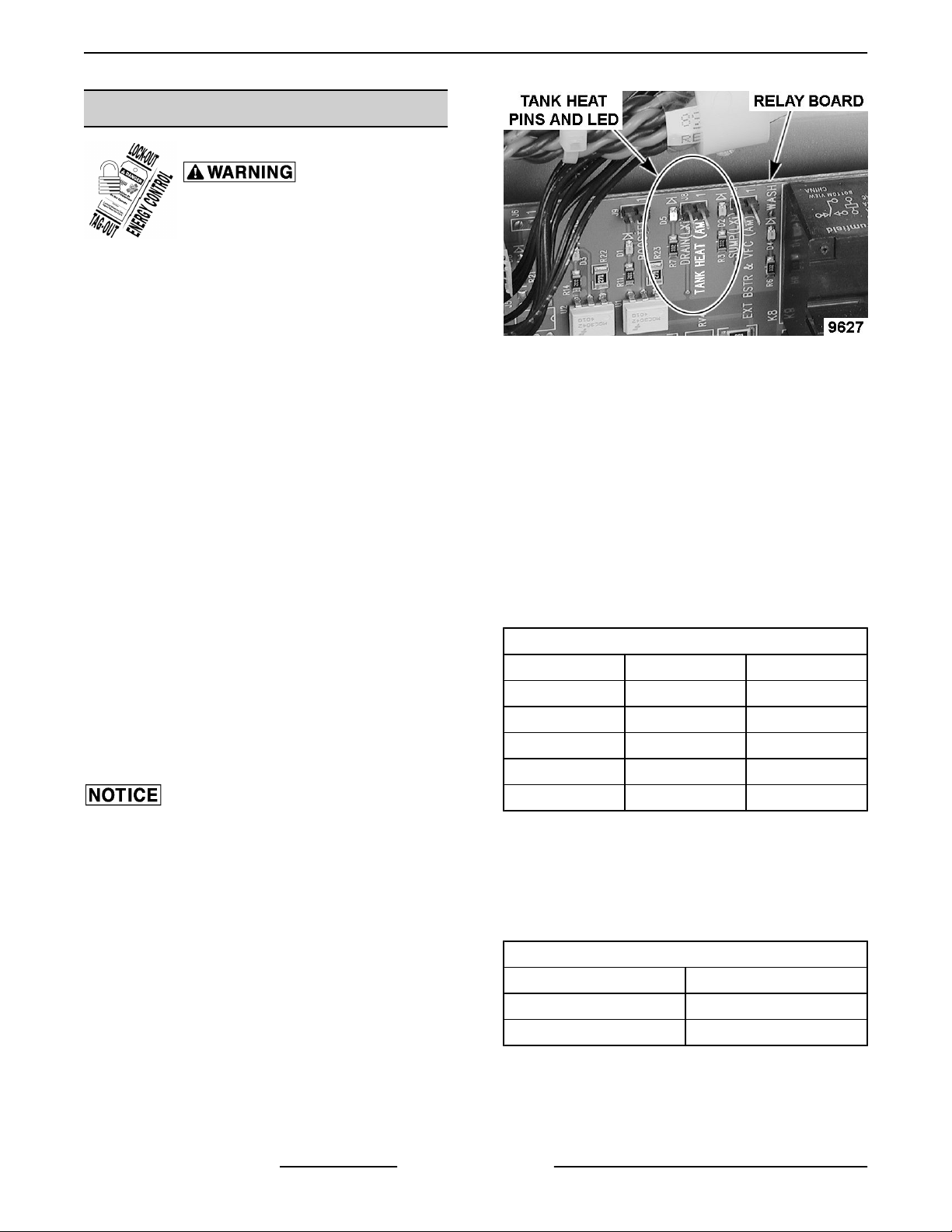
heat (relay board TANK HEAT LED not lit),
run machine through a cycle to activate tank
heater. Alternately, short the relay board
TANK HEAT (AM) -J8 pins together to
energize the tank heater.
Fig. 4
6. While the TANK HEAT (AM) LED is on, verify that
the tank heat contactor 2CON is energized.
A. If contactor is not energized, check for
120VAC across coil.
1) If 120VAC is not present, check high
limit thermostat 1TAS.
B. If contactor is energized, check:
1) Voltage across all legs on load side of
contactor.
2) Current flow through all elements of
heater.
RATED TANK HEATER ELEMENT CURRENTS
Voltage/Phase Amperes Power (Watts)
208/60/1 26A 5.4kW
240/60/1 30A 7.2kW
208/60/3 15A 5.4kW
240/60/3 17.3A 7.2kW
480/60/3 6A 5kW
7. If the current reading on any of the elements is
not correct:
A. Check the contacts of contactor 2CON.
B. Check the wash tank heater element
resistance.
INDIVIDUAL TANK ELEMENT RESISTANCE
Voltage Cold Resistance
208 - 240V 21.7 - 25.1Ω
480V 105 - 121.7Ω
SD3 Series - SERVICE PROCEDURES AND ADJUSTMENTS
F45576 (1015) Page 10 of 37

BOOSTER HEATER - TEST
Certain procedures in
this section require electrical test or
measurements while power is applied
to the machine. Exercise extreme
caution at all times and follow Arc Flash
procedures. If test points are not easily
accessible, disconnect power and
follow Lockout/Tagout procedures,
attach test equipment and reapply
power to test.
NOTE: Tank must be filled with water (float switch
closed) in order to test booster heat circuit.
1. Measure incoming voltage and verify it matches
machine specifications.
2. Remove FRONT COVER.
3. Open control door.
4. Apply power to machine and booster.
A. Measure incoming voltage across line side
of the tank contactor 2CON and booster
contactor 3CON. Verify voltages match
machine specifications on data plate.
5. Verify the following conditions are met.
A. Tank is full of water.
B. Float switch 1FS is closed.
C. Booster thermistor 3QTM is good, not open
or shorted.
D. There is a demand for heat (booster water
temperature is below set point).
6. Turn machine on.
Shorting J9 terminals together without
having water in the tank may result in damaging the
tank heater.
A. If temperature control circuit is not calling for
heat (relay board BOOSTER LED not lit),
run machine through a cycle to activate
booster heater. Alternately, short the relay
board pins BOOSTER - J9 together to
energize the booster heater.
Fig. 5
7. While the BOOSTER LED is on, verify that the
booster contactor 3CON is energized.
A. If contactor is not energized, check for
120VAC across coil.
1) If 120VAC is not present, check high
limit thermostats 2TAS and 3TAS.
B. If contactor is energized, check:
1) Voltage across all legs on load side of
contactor.
2) Current flow through all elements of
heater.
BOOSTER HEATER ELEMENT CURRENTS
Voltage/Phase Amperes Power (Watts)
200/60/1 45.1A 9kW
208/60/1 40.7A 9.8kW
240/60/1 54.2A 13kW
200/60/3 26A 9kW
208/60/3 27.2A 9.8kW
240/60/3 31.3A 13kW
480/60/3 13.6A 13kW
8. If the current reading on any of the elements is
not correct:
A. Check the contacts of contactor 3CON.
B. Check the booster heater element
resistance.
INDIVIDUAL ELEMENT RESISTANCE
Voltage Cold Resistance
200 - 208V 9.0 - 10.5Ω
220 - 240V 12 - 13.9Ω
380 - 415 30.2 - 34.9Ω
440 - 480V 48.2 - 55.7Ω
SD3 Series - SERVICE PROCEDURES AND ADJUSTMENTS
Page 11 of 37 F45576 (1015)

INDIVIDUAL ELEMENT RESISTANCE
Voltage Cold Resistance
575 - 600V 75.3 - 87.0Ω
PUMP MOTOR - TEST
Certain procedures in
this section require electrical test or
measurements while power is applied
to the machine. Exercise extreme
caution at all times and follow Arc Flash
procedures. If test points are not easily
accessible, disconnect power and
follow Lockout/Tagout procedures,
attach test equipment and reapply
power to test.
NOTE: The pump motor for all machines is rated at 2
H.P. and has thermal overload protection.
1. Remove FRONT COVER.
2. Open control door.
3. Apply power and measure incoming voltage
verifying it meets machine requirements.
4. Turn machine on and take an amperage reading
of one of the tank heater leads connected to
contactor (2CON).
SD3 MOTOR CURRENTS (Maximum)
Voltage/phase Amps
208/60/1 11.0A
240/60/1 10.6A
208/60/3 5.6A
240/60/3 5.4A
480/60/3 2.7A
NOTE: Current consumption for a normally operating
pump and motor assembly will be less than the
amperage values listed.
5. If motor current exceeds those values listed in the
table, inspect pump for blockage causing a
locked-rotor condition.
A. If blockage is not present, replace motor.
6. If current in one phase of a three phase motor is
low or missing, also inspect incoming line
service, contactor 1CON and other related
circuitry to missing phase.
THERMISTOR - TEST 1QTM, 2QTM
& 3QTM
Certain procedures in
this section require electrical test or
measurements while power is applied
to the machine. Exercise extreme
caution at all times and follow Arc Flash
procedures. If test points are not easily
accessible, disconnect power and
follow Lockout/Tagout procedures,
attach test equipment and reapply
power to test.
NOTE: The temperature/resistance characteristics
are the same for all the thermistors used in SD3.
NOTE: The resistance of each thermistor can be
measured by removing the plug connected to J2 on
the control board.
1. Remove FRONT COVER.
2. Open control door.
Quick Check Using Service Diagnostics
1. Enter Service Diagnostics mode.
A. Apply power. With machine off, press and
hold the PROG and SELECT switches on
control board and press and release the ON
key on the switch membrane keypad.
B. Continue to hold in on the PROG and
SELECT switches until display shows [ 88 ]
then release both switches.
NOTE: XXX represents the actual water temperature.
C. Press the SELECT switch repeatedly until
[ WASH XXX°F (°C) ] which is tank water
temperature.
D. Press the SELECT switch once to display
[ XXX°F (°C) RINSE ] which is rinse water
temperature.
E. Press the SELECT switch once to display
[ WASH XXX°F (°C) RINSE ] which is
booster water temperature.
Measuring Thermistor Resistance
1. Disconnect the plug from J2 on the control board.
SD3 Series - SERVICE PROCEDURES AND ADJUSTMENTS
F45576 (1015) Page 12 of 37

Fig. 6
2. Refer to the following photograph to locate the
thermistor leads of interest.
Fig. 7
PINS FOR THERMISTORS AND FLOAT
SWITCH
3. Refer to the table that follows for thermistor
resistance values.
TEMPERATURE VS. RESISTANCE FOR 1QTM,
2QTM AND 3QTM THERMISTORS
DEGREE (°F) RESISTANCE (Ω)
70°F 120 kΩ
80°F 91 kΩ
90°F 72 kΩ
100°F 55 kΩ
110°F 44 kΩ
120°F 34.5 kΩ
130°F 28 kΩ
140°F 22.5 kΩ
150°F 18 kΩ
160°F 14.5 kΩ
170°F 12 kΩ
180°F 10 kΩ
TEMPERATURE VS. RESISTANCE FOR 1QTM,
2QTM AND 3QTM THERMISTORS
DEGREE (°F) RESISTANCE (Ω)
190°F 8.2 kΩ
200°F 6.9 kΩ
210°F 5.8 kΩ
250°F 2.9 kΩ
257°F 2.626 kΩ
284°F 1.734 kΩ
290°F 1.6 kΩ
TRANSFORMER 1T - TEST
Certain procedures in
this section require electrical test or
measurements while power is applied
to the machine. Exercise extreme
caution at all times and follow Arc Flash
procedures. If test points are not easily
accessible, disconnect power and
follow Lockout/Tagout procedures,
attach test equipment and reapply
power to test.
NOTE: Transformer 1T steps down incoming line
voltage to 120VAC for use by the machine's control
components.
1. Remove FRONT COVER.
2. Open control door.
3. Remove right side cover.
4. Verify transformer is strapped correctly by
comparing connection wiring points on
transformer with machine data plate.
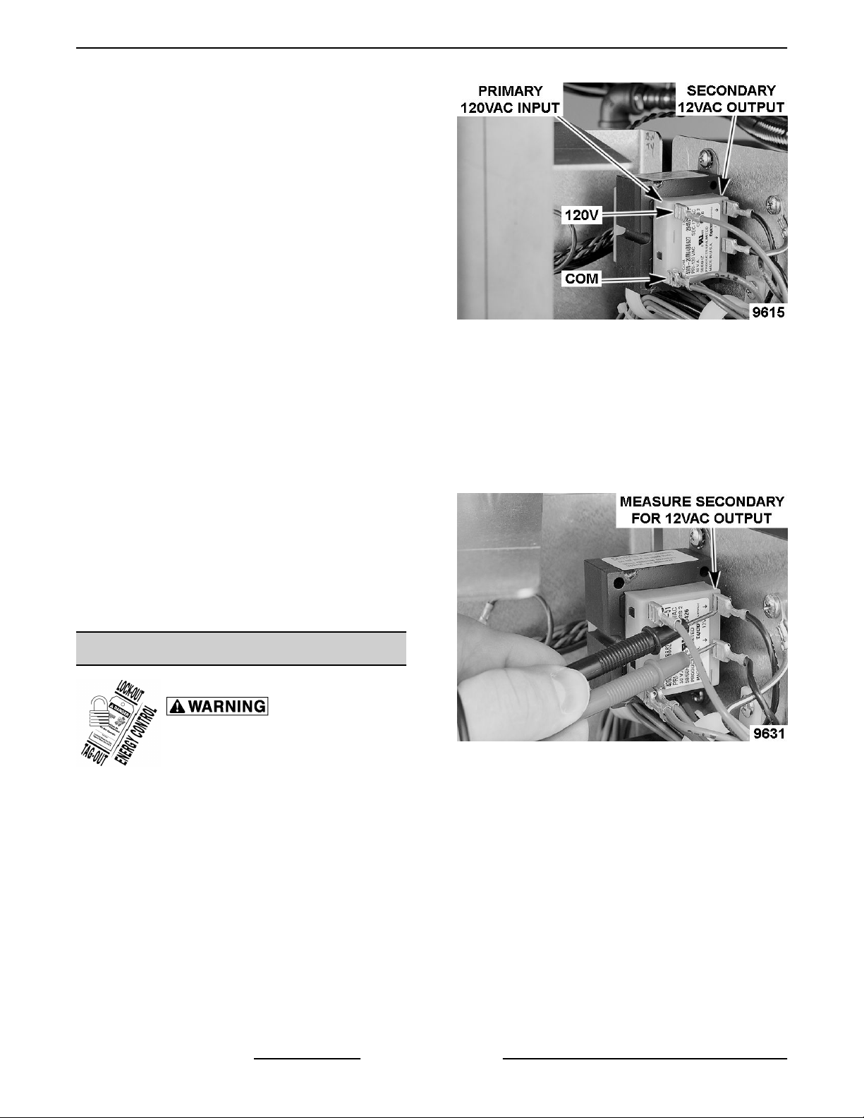
Fig. 8
SD3 Series - SERVICE PROCEDURES AND ADJUSTMENTS
Page 13 of 37 F45576 (1015)
5. Connect power to machine.
6. Verify incoming AC line voltage at the line service
connection point.
7. Verify incoming voltage is present to primary side
of transformer 1T.
8. Measure output AC voltage across secondary
windings of transformer. Voltage should be
approximately 120VAC.
A. If voltage is present, transformer is
functioning.
B. If output voltage is not present, verify
transformer wiring connections.
1) If connections are correct, replace
transformer.
C. If output voltage is low, disconnect power
from machine.
1) Disconnect one side of the secondary.
2) Apply power to machine.
3) Check output voltage across
secondary windings.
a. If voltage is still low, replace
transformer.
b. If voltage is approximately
120VAC, check components and
related wiring connected to the
secondary.
TRANSFORMER 2T - TEST
Certain procedures in
this section require electrical test or
measurements while power is applied
to the machine. Exercise extreme
caution at all times and follow Arc Flash
procedures. If test points are not easily
accessible, disconnect power and
follow Lockout/Tagout procedures,
attach test equipment and reapply
power to test.
1. Remove FRONT COVER.
2. Open control door.
3. Remove right side cover.
4. Connect power to machine.
5. Verify incoming 120VAC voltage is present to
primary side of transformer 2T.
Fig. 9
A. If 120VAC is not present, check fuse F2 on
relay board.
1) If fuse is good, perform
TRANSFORMER 1T - TEST.
6. Measure output AC voltage across secondary
windings of transformer. Voltage should range
between (11.5 - 16VAC).
Fig. 10
A. If voltage is present at output, transformer is
functioning.
B. If voltage is not present at output, verify
transformer wiring connections.
1) If connections are correct, replace
transformer.
C. If voltage is low, disconnect power from
machine.
1) Disconnect one side of the secondary.
2) Apply power to machine.
3) Check voltage across secondary
windings.
SD3 Series - SERVICE PROCEDURES AND ADJUSTMENTS
F45576 (1015) Page 14 of 37
a. If voltage at output is still low,
replace transformer.
b. If voltage at output is between
11.5 - 16VAC, check the control
board assembly.
DELIMIMG PROCEDURE
DELIMING SOLUTION, RINSE
AGENTS, OR ANY OTHER KIND OF ACID MUST
NOT COME IN CONTACT WITH BLEACH OR RINSE
SOLUTION CONTAINING BLEACH USED IN
CHEMICAL SANITIZING MACHINES. MIXING MAY
CAUSE HAZARDOUS GAS TO FORM. THIS
ENTIRE PROCEDURE MUST BE FOLLOWED
STEP-BY-STEP FOR SAFE AND SATISFACTORY
RESULTS.
1. Remove rack, drain tank, press "OFF".
2. Press and hold "Cycle & "ON for three seconds.
3. Open door & add delime agent per supplier
instructions for 14 gallon tank.
4. Close door, pump starts & display flashes
“DELIME”. After 12 minutes display scrolls
“DRAIN ”.
5. Check interior, close door to run additional cycles
if necessary.
6. Drain tank, turn unit off.
NOTE: The delime counter feature is disabled from
the factory.
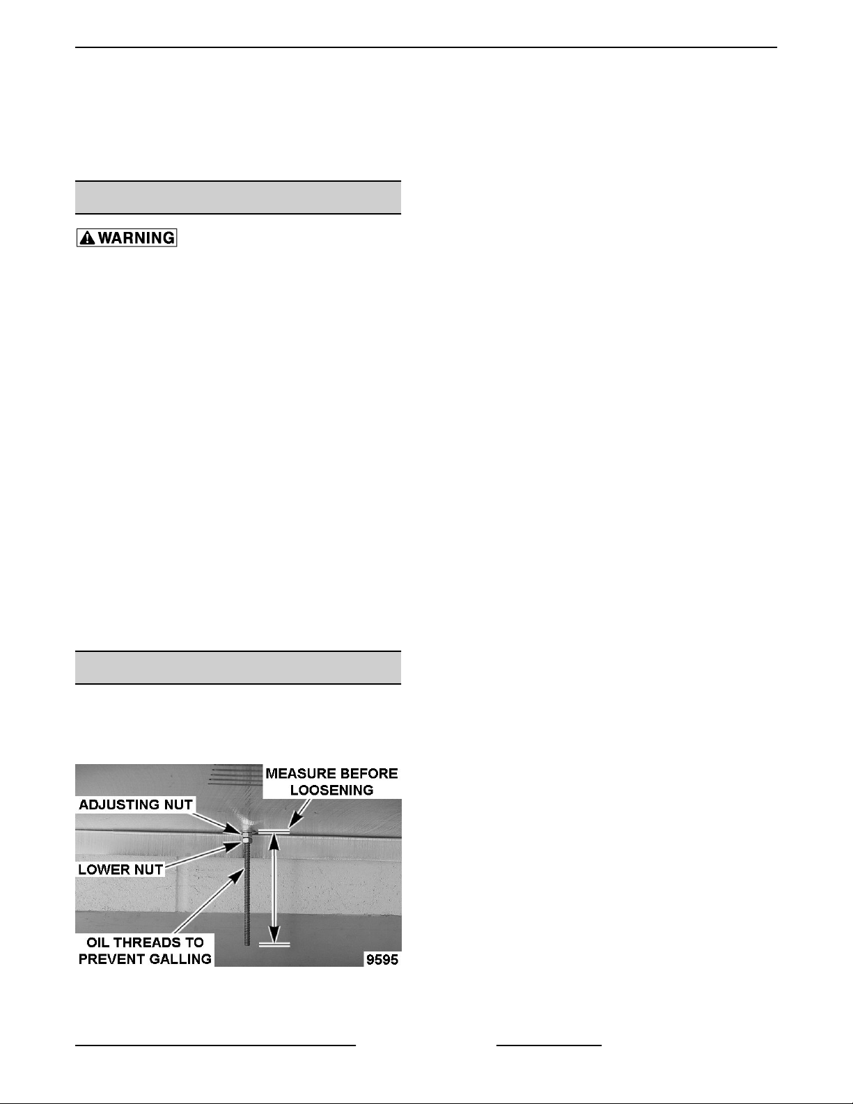
DOOR TENSION ADJUSTMENT
NOTE: Door is adjusted correctly if the door remains
in place at any position.
1. Loosen lock nut.
Fig. 11
2. Holding the spring rod in position to prevent
rotation, adjust the nut to provide proper tension.
3. Lock adjusting nut in position with lower nut.
SD3 Series - SERVICE PROCEDURES AND ADJUSTMENTS
Page 15 of 37 F45576 (1015)

ELECTRICAL OPERATION
COMPONENT FUNCTION
Control Board
Assembly .............
Controls dishwasher electrical operation.
Relay Board .......... Controlled by control board assembly, the on board relays and fuses deliver energy to
machine control components.
Fuse, Relay Board
(F1) ...................
1/10A fuse. Protects rinse feeder 1CR coil circuit.
Fuse, Relay Board
(F2) ...................
1.0A fuse. Protects primary of transformer 2T, 1CON, 2CON, 3CON, 1SOL and external
booster control from over-currents.
Switch Membrane
Keypad ...............
User interface to machine. Used to select wash mode and program control board
assembly.
Display Module ....... Provides machine information to user through the use of LEDs, lighted icons, and
illuminated text and numbers.
Contactor (1CON) ..... Controls electrical power to wash pump (120VAC coil).
Contactor (2CON) ..... Controls electrical power to wash tank heater (120VAC coil).
Contactor (3CON) ..... Controls electrical power to booster heater (120VAC coil).
Relay (1CR) ........... Controlled by the control board assembly through the relay board, provides a means of
controlling energy to RPS1 and RPS2 on terminal block 3TB.
Float Switch (1FS) .... Detects water level in tank. On SD3, control board only uses Low Water Level LED with
the float switch.
Heater, Booster (BSTR
HTR) ..................
Heating element for booster (8.5kW).
Heater, Tank (Tank
HTR) ..................
Heating element for wash tank (5kW to 7.2kW).
High Limit Thermostat
(1TAS) ................
Protects tank heater circuit.
High Limit Thermostat
(2TAS) ................
Protects booster circuit. Frame mounted, capillary design
High Limit Thermostat
(3TAS) ................
Protects booster circuit. Mounted on the booster.
Interlock Switch
(1LS) ..................
Feed back to control board on state of door (open or closed).
Solenoid (1SOL) ...... Fill/rinse solenoid.
Thermistor, Wash
(1QTM) ................
Senses tank water temperature.
Thermistor, Rinse
(2QTM) ................
Senses rinse water temperature
Thermistor, Booster
(3QTM) ................
Senses booster water temperature
Terminal Block
(1TB) ..................
Line service to tank contactor 2CON (1 phase only).
SD3 Series - ELECTRICAL OPERATION
F45576 (1015) Page 16 of 37

Terminal Block
(2TB) ..................
Line service to booster contactor 3CON (1 phase only).
Terminal Block
(3TB) ..................
Connection point for detergent and rinse aid control devices.
Transformer (1T) ..... Provides 120VAC to control circuit and 2T.
Transformer (2T) ..... Provides 12VAC to control board.
COMPONENT LOCATION
Control Door Mounted Components
NOTE: The components present are determined by
the voltage, hertz, phase, and options on the
dishwasher.
Control Panel Mounted Components
SD3 Series - ELECTRICAL OPERATION
Page 17 of 37 F45576 (1015)

CONTROL BOARD / RELAY BOARD LAYOUT
Control Board
SD3 Series - ELECTRICAL OPERATION
F45576 (1015) Page 18 of 37

Relay Board
NOTE: DETERGENT AND RINSE AID CIRCUITS
NOT USED ON SD3.
SEQUENCE OF OPERATION
Refer to the correct wiring diagram for model being
serviced when reviewing sequence of operation.
WIRING DIAGRAM - 3 PHASE
WIRING DIAGRAM - 1 PHASE
Initial Conditions
• Door up (Door Interlock 1LS open).
• Dishwasher tank empty (Float 1FS open).
• Water supply requirements (110°F @ 20 ± 5 psi)
to machine are satisfied.
• Voltage supplied to machine is correct.
• High limits are closed.
1. Machine is off. Display is not lit.
A. Line voltage present at the following
components.
1) Primary windings of transformer 1T.
2) Line sides of 1CON (pump motor) and
2CON (tank heater).
3) Booster heater line side of 3CON.
4) Relay terminals 1CR 4 and 8.
B. 120VAC from transformer 1T present at the
following components.
1) Triac Q2 (1CR coil) thru fuse F1.
2) Primary windings of transformer 2T
thru fuse F2.
3) Triac Q3 (3CON coil) thru fuse F2.
4) Triac Q4 (1SOL) thru fuse F2.
SD3 Series - ELECTRICAL OPERATION
Page 19 of 37 F45576 (1015)

5) Relay board relays K5-C, K8-C and K9-
C thru fuse F2.
NOTE: It is normal for the secondary voltage (output)
from transformer 2T to range between 11.5 to 16VAC.
C. 12VAC present to control board J1-1/3 from
secondary windings of transformer 2T.
Acceptable voltage is 11.5 - 16VAC.
1) Power supply on control board
converts AC voltage to 12VDC and
5VDC to power control board, display
and membrane switch.
2. ON key on membrane switch is pressed.
A. Control board enters self-test, also tests
display LEDs.
B. K5 coil on relay board energize.
1) EXT BSTR & VFC (AM) LED on relay
board turns on.
3. Self-test completes.
A. Machine type (AP, AH or AC) is displayed
followed by tank temperature.
B. MICRO LED on control board blinks at a 1
second on - 1 second off rate.
C. 5VDC present across 1QTM, 2QTM, 3QTM
and open contacts of 1FS.
D. Tank temperature is displayed.
E. Membrane switch - last selected cycle LED
is on. Cycle selection is enabled.
4. Door is shut.
A. Door interlock switch 1LS closes.
B. Control board senses float switch is open
and energizes fill/rinse solenoid 1SOL
through relay board. Tank begins to fill.
1) FILL LED on relay board turns on.
C. FILL icon and tank temperature are
displayed on display board.
NOTE: Once tank float switch is closed, a wash cycle
can be started by opening and closing the door even
though fill is not complete.
D. Tank float 1FS closes.
1) LOW LEVEL WATER LED on control
board turns on.
2) Control board energizes 3CON coil
through the relay board. 3CON
contacts close energizing booster
heater.
a. BOOSTER LED on relay board
turns on.
3) Control board signals relay board
(relay K9) to energize 2CON coil.
2CON contacts close energizing tank
heater.
a. TANK HEAT (AM) LED on relay
board turns on.
5. Depending on the fill time required to close float
switch 1FS, the control board will fill an additional
amount of time (75 - 120 seconds) after which
time the control board de-energizes the fill/rinse
solenoid 1SOL through the relay board.
A. FILL LED on relay board turns off.
NOTE: Tank Heat and Booster circuits remain
energized until set point has been reached; however,
a wash cycle may be started at any point.
6. Booster temperature reaches set-point.
A. Control board de-energizes 3CON coil
through the relay board. 3CON contacts
open de-energizing booster heater.
1) BOOSTER LED on relay board turns
off.
7. Tank temperature reaches set-point.
A. Control board de-energizes 2CON coil
through the relay board. 2CON contacts
open de-energizing tank heater.
1) TANK HEAT (AM) LED on relay board
turns off.
8. Door is opened and closed.
A. Control board senses that float switch 1FS
was closed before the door was closed and
energizes relay K8 on relay board. 1CON
contacts close energizing the pump motor
MTR. A wash cycle begins.
1) WASH LED on relay board turns on.
2) Machine line voltage present at
terminals DPS1 and DPS2.
9. Wash cycle.
A. The WASH icon and water temperature are
displayed.
B. Wash cycle continues for time selected.
C. Wash cycle completed.
1) Relay board K8 de-energizes. Wash
coil (1CON) de-energizes and pump
N.O. contacts open. Pump stops.
SD3 Series - ELECTRICAL OPERATION
F45576 (1015) Page 20 of 37
This manual suits for next models
2
Table of contents
Other STERO Dishwasher manuals


Popular Dishwasher manuals by other brands


Pelgrim
Pelgrim GVW448ONY Instructions for use

Fisher & Paykel
Fisher & Paykel DishDrawer DD605 Series installation instructions

Gaggenau
Gaggenau DF481101F INFORMATION FOR USE

Johnson
Johnson JWAS10EINT instruction manual

Classeq
Classeq C200G Installation & operator's manual

Asko
Asko D5894XXLFI installation instructions