STERO SG Building instructions

SG, SU-L, SU-H DISHWASHERS
SG
SU-L
SU-H
SERVICE and PARTS MANUAL
F45577 (1215)

TABLE OF CONTENTS
GENERAL .................................................................................................. 4
INTRODUCTION ....................................................................................... 4
MODELSCOVERED ................................................................................... 4
TOOLS ................................................................................................. 4
ELECTRICAL SPECIFICATIONS ....................................................................... 4
ENGINEERINGDATA .................................................................................. 5
INSTALLATION AND OPERATION CYCLES ............................................................ 5
PROGRAMMING MENUS .............................................................................. 6
REMOVAL AND REPLACEMENT OF PARTS ............................................................... 7
CONTROL PANEL SERVICE POSITION ................................................................ 7
LEFTANDRIGHTTRIMPANELS ...................................................................... 7
SWITCH MEMBRANE .................................................................................. 8
CONTROLPANELCOVER ............................................................................. 8
WATER LEVEL SENSORS ............................................................................. 9
CHEMICAL PUMPS - WELCO ......................................................................... 10
DRAINPUMP ......................................................................................... 10
FILLVALVE(1SOL) ................................................................................... 11
RINSEPUMP ......................................................................................... 11
RINSEPROBE(2QTM) ............................................................................... 12
WASH PIPE ASSEMBLY .............................................................................. 13
WASH PUMP/MOTOR (1MTR) ........................................................................ 14
BOOSTERHEATER(SU-H) ........................................................................... 15
BOOSTER THERMISTOR & HIGH LIMIT PROTECTION (SU-H) ....................................... 15
SUMP THERMISTOR & HIGH LIMIT PROTECTION ................................................... 16
AIRGAP .............................................................................................. 16
DOORSWITCH ....................................................................................... 17
SERVICEPROCEDURESANDADJUSTMENTS ........................................................... 18
REPLACEMENT CONTROL BOARD PROGRAMMING ................................................ 18
SERVICE PROGRAMMING (8934) .................................................................... 18
SOAP PROGRAMMING (7627) ........................................................................ 25
MANAGER PROGRAMMING (1001) ................................................................... 27
TESTING SANITIZER (BLEACH) CONCENTRATION (P.P.M.) ......................................... 29
BYPASS WASH/HEAT CYCLES FOR TROUBLESHOOTING .......................................... 30
10KOHMTHERMISTORTEST-BOOSTER(3QTM)&SUMP(1QTM) ................................. 30
PURGEBOOSTER/HOLDINGTANKFORSERVICE ................................................... 31
DOORADJUSTMENT ................................................................................. 31
SUMPHEATERTEST ................................................................................. 32
BOOSTERHEATERTEST ............................................................................ 32
100K OHM THERMISTOR TEST - RINSE PROBE (2QTM) ............................................. 33
ELECTRICAL OPERATION ................................................................................ 34
COMPONENT FUNCTION ............................................................................ 34
COMPONENTLAYOUT ............................................................................... 35
CONTROLBOARDLEDS ............................................................................. 37
CONTROLBOARDTESTPOINTS .................................................................... 38
CONTROL BOARD JUMPERS ........................................................................ 40
CONTROL BOARD WIRE CONNECTIONS ............................................................ 41
POWERSUPPLYBOARDLEDS&TESTPOINTS ..................................................... 42
SU-L&SGWIRINGDIAGRAM ........................................................................ 43
SU-H(3WIRE-1PH)WIRINGDIAGRAM .............................................................. 45
SU-L & SG SEQUENCE OF OPERATION ............................................................. 47
SU-H SEQUENCE OF OPERATION ................................................................... 49
CYCLETIMINGCHART ............................................................................... 52
TROUBLESHOOTING ..................................................................................... 53
SG, SU-L, SU-H DISHWASHERS
F45577 (1215) Page 2 of 59

TOGGLE DIAGNOSTICS .............................................................................. 53
ERRORCODES ...................................................................................... 53
TROUBLESHOOTING GUIDE WARE .................................................................. 55
TROUBLESHOOTING GUIDE MACHINE .............................................................. 56
SG, SU-L, SU-H DISHWASHERS
© COMPETITIVE 2015
Page 3 of 59 F45577 (1215)
PARTS CATALOG .................................................................................... 60
GENERAL
INTRODUCTION
This manual is applicable to the models on the cover
page. Procedures apply to all models unless specified
otherwise.
MODELS COVERED
The SU and SG Series dishwashers are fully
automatic, front-loading dishwashing machines.
SU-L 33 racks per hour
SU-H 31 racks per hour
SG 34 racks per hour
All SU and SG Series dishwashers shut down
automatically 4 hours after last use to conserve
energy.
SU-H dishwashers include Rinse Assurance to insure
proper hot water temperature during rinse.
MODEL DESCRIPTION
SU-L
SG
Fresh water rinse; low-temperature,
chemical-sanitizing models for use
with 6% or 8.40% sodium hypochlorite
solution (bleach) as the sanitizing
agent.
SU-H
Fresh water rinse with a built-in 70° F
rise booster heater. This allows an
incoming water temperature of 110° F.
TOOLS
Standard
• Standard set of hand tools.
• Metric set of hand tools.
• VOM with measuring micro amp current tester.
Any VOM with minimum of CAT III 600V, CE
certified. Sensitivity of at least 20,000 ohms per
volt can be used. In addition, meter leads must
also be a minimum of CAT III 600V.
• Temperature tester (thermocouple type).
• Field service grounding kit.
Special
• Precision Chlorine Test Paper Vial, for testing
sanitizer p.p.m.
• Cleaner used in removal of switch membrane.
• T25 Torx bit. Used in removal of door.
• Service Tool: Used in removal of Wash Pump Nut
and Wash Manifold Nut.
Fig. 1
ELECTRICAL SPECIFICATIONS
NOTE: Always check incoming voltage to verify
service connection meets machine specification.
ELECTRICAL SPECIFICATIONS
Model Volts / Hertz / Phase Rated Amps
Minimum Supply
Circuit Conductor
Ampacity
Maximum Protective
Device Ampacity
SG 120/60/1 15.4 20 20
SU-L 120/60/1 13.4 20 20
SU-H
120/208-240(3W)/60/1 30.5 40 40
NOTE: This system requires three power wires that include a current carrying neutral. An additional
fourth wire must be provided for machine ground.
SG, SU-L, SU-H DISHWASHERS - GENERAL
F45577 (1215) Page 4 of 59

ENGINEERING DATA
3/4 HP pump motor, thermally protected internally, automatic reset.
Required water supply characteristics are as follows:
Model Temperature Flowing Pressure
SG
SU-L 120°F minimum 15 - 65 psi
SU-H 110°F minimum 15 - 65 psi
INSTALLATION AND OPERATION
CYCLES
INSTALLATION
Generally, all installations are made by the
dealer or others contracted by the dealer or
owner.
POWER-UP DIAGNOSTICS
When the Power Button is pressed, the control
board checks the probes and sensors to be
within operational range. Once the self-check is
passed, the machine automatically enters Fill/
Preheat Mode.
NOTE: If there is a detectable water level in the
sump prior to turning the machine on, the
dishwasher will perform a power drain.
PRIMING CHEMICAL PUMPS
Chemical pumps prime on Power Up or at the
start of a Wash Cycle if sensors do not detect
chemicals.
1. Initial prime attempt is 60 seconds.
A. If chemical not sensed "Add Chemical" will
display.
NOTE: The 60 second prime is in intervals of 6
seconds.
2. If not primed after 3 attempts, the "Add
Chemical" indicator will continue to display.
3. Priming is terminated.
4. Reset by cycling power.
5. Once chemical is sensed, pumps continue to
prime for 10 seconds to allow chemicals to reach
machine.
FILL/PREHEAT
Without Booster (SG & SU-L): The holding
tank will fill. The water is then moved through the
rinse arms to the sump. Process repeats until
the sump is at operational water level. Sump
heater maintains wash temperature.
With Booster (SU-H): The booster will fill and
heat to 140°F. The booster water is then moved
through the rinse arms to the sump. Process
repeats until the sump is at operational water
level. Sump heater maintains wash
temperature.
NOTE: If the door is opened during the Fill
cycle, the process is suspended. After door is
closed the process continues where it left off.
NOTE: During the Fill cycle, the detergent pump
is activated for the normal detergent cycle.
READY MODE
While a cycle is not in process, the SU and SG
Series will maintain in idle state. In this mode,
the heat will be maintained in both the sump and
booster. The sump temperature will be
displayed.
NORMAL OPERATION (WASH CYCLE)
After the fill cycle is completed, a wash cycle is
begun by pressing the WASH key.
On 120VAC cold machines, sump heater is de-
energized while wash motor is energized.
If the door is opened during the Wash cycle, the
process is suspended. After door is closed the
process continues where it left off.
During a cycle, both sump and booster heat are
controlled. Hot machines only.
During the wash portion of the cycle, the sump
temperature will be displayed. During the rinse,
the final rinse temperature will be displayed.
RINSE
SG, SU-L, SU-H DISHWASHERS - GENERAL
Page 5 of 59 F45577 (1215)

After the wash cycle ends, water is drained from
the sump to allow for the rinse water from the
holding tank (cold machines) or booster (hot
machines).
POWER-DOWN / DRAIN
When the POWER key is pressed, the unit will
enter a drain cycle. Booster or holding tank will
be purged, and sump will be drained. After the
completion of the drain cycle, power to the
controls is removed under software control. At
this point, the control is inoperable until the
POWER key is pressed.
PROGRAMMING MENUS
There are 3 Programming Menus that can be
accessed when the Menu/Down Arrow button is
selected. Each menu has parameters that can be
changed that affects the way the dishwasher
operates. Each menu is protected by a 4 digit access
code.
Use the arrow keys to change the ( -> ) to the desired
number and press enter to move to the next digit.
NOTE: The Manager Programming menu uses 1001
as the access code. Just select enter to move to the
next digit.
•MANAGER PROGRAMMING (1001)
•SOAP PROGRAMMING (7627)
•SERVICE PROGRAMMING (8934)
SG, SU-L, SU-H DISHWASHERS - GENERAL
F45577 (1215) Page 6 of 59

REMOVAL AND REPLACEMENT OF PARTS
CONTROL PANEL SERVICE
POSITION
Disconnect the
electrical power to the machine and
follow lockout / tagout procedures.
Certain components in this system are
subject to damage by electrostatic discharge during
field repairs. A field service grounding kit is required
to prevent damage. The field service kit must be used
anytime the control board is handled.
1. Pull dishwasher out from underneath counter.
2. Open door and remove two screws using #3
Phillips screwdriver.
Fig. 2
3. Pull out control cover, then hinge up and back.
Fig. 3
4. Reverse procedure to install.
5. Check for proper operation.
LEFT AND RIGHT TRIM PANELS
Disconnect the
electrical power to the machine and
follow lockout / tagout procedures.
Certain components in this system are
subject to damage by electrostatic discharge during
field repairs. A field service grounding kit is required
to prevent damage. The field service kit must be used
anytime the control board is handled.
Control Panel Service Position
1. Open door and remove (2) screws.
Fig. 4
2. Slide control cover forward (Approximately 2-3").
Left and Right Trim Panel Removal
1. Remove left and right trim panel screws, using #3
Phillips screwdriver.
Fig. 5
2. Remove left and right trim panels.
3. Close unit door.
SG, SU-L, SU-H DISHWASHERS - REMOVAL AND REPLACEMENT OF PARTS
Page 7 of 59 F45577 (1215)
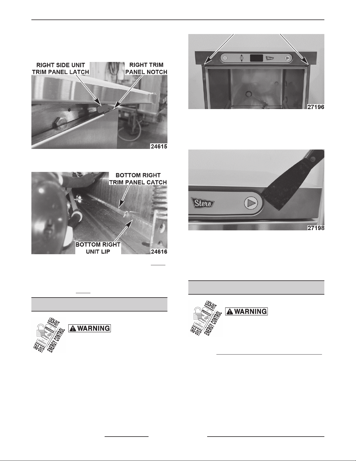
Left and Right Trim Panel Installation
1. Insert right trim panel notch into right side unit
trim panel latch.
2. Verify bottom right trim panel catch is fastened to
the bottom right lip of the unit.
3. Insert and tighten right trim panel screw. (Fig. 5)
4. Repeat steps 1 - 3 for left trim panel installation.
5. Slide control cover back in place and tighten with
(2) screws. (Fig. 4)
SWITCH MEMBRANE
Disconnect the
electrical power to the machine and
follow lockout / tagout procedures.
1. Open door and remove screws, using #3 Phillips
screwdriver.
Fig. 8
2. Pull out control cover and disconnect switch
membrane ribbon cable from connector.
3. Pry up switch membrane.
Fig. 9
4. Reverse procedure to install.
NOTE: Before installing replacement membrane, use
cleaner to remove old adhesive and allow to dry.
5. Check for proper operation.
CONTROL PANEL COVER
Disconnect the
electrical power to the machine and
follow lockout / tagout procedures.
1. Pull dishwasher out from underneath counter,
when CONTROL PANEL SERVICE POSITION
is not possible or entire cover needs replaced.
2. Open door and remove two screws, using #3
Phillips screwdriver.
SG, SU-L, SU-H DISHWASHERS - REMOVAL AND REPLACEMENT OF PARTS
F45577 (1215) Page 8 of 59

Fig. 10
3. Slide control cover forward and disconnect
switch membrane ribbon cable from connector.
4. Loosen nut, washer and center bearing washer
from both sides. (Do NOT remove hardware)
Fig. 11
5. Remove control cover.
6. Reverse procedure to install.
NOTE: Center bearing washer must be centered in
hole to allow rotation.
Fig. 12
7. Check for proper operation.
WATER LEVEL SENSORS
Disconnect the
electrical power to the machine and
follow lockout / tagout procedures.
1. Remove CONTROL PANEL COVER.
2. Remove LEFT AND RIGHT TRIM PANELS
(Booster/Holding Tank) or LEFT AND RIGHT
TRIM PANELS (Sump tank).
3. Drain sump or Booster/Holding tank below air
trap (1, Fig. 13) inlet.
NOTE: Not draining sump or booster / holding tank
may cause a leak.
Fig. 13
4. Disconnect water level cable from sensor and
tube clamp.
5. Push plastic tabs (using screwdriver or pliers) to
remove.
NOTE: Do NOT over squeeze pinch clamps on
bottom of sensors.
Fig. 14
SG, SU-L, SU-H DISHWASHERS - REMOVAL AND REPLACEMENT OF PARTS
Page 9 of 59 F45577 (1215)

6. Reverse procedure to install.
A. Verify there is no water in air trap.
B. Verify there is no water, kinks or holes in
pressure sensor tubing.
C. Verify tubing clamp is properly installed.
7. Check for proper operation.
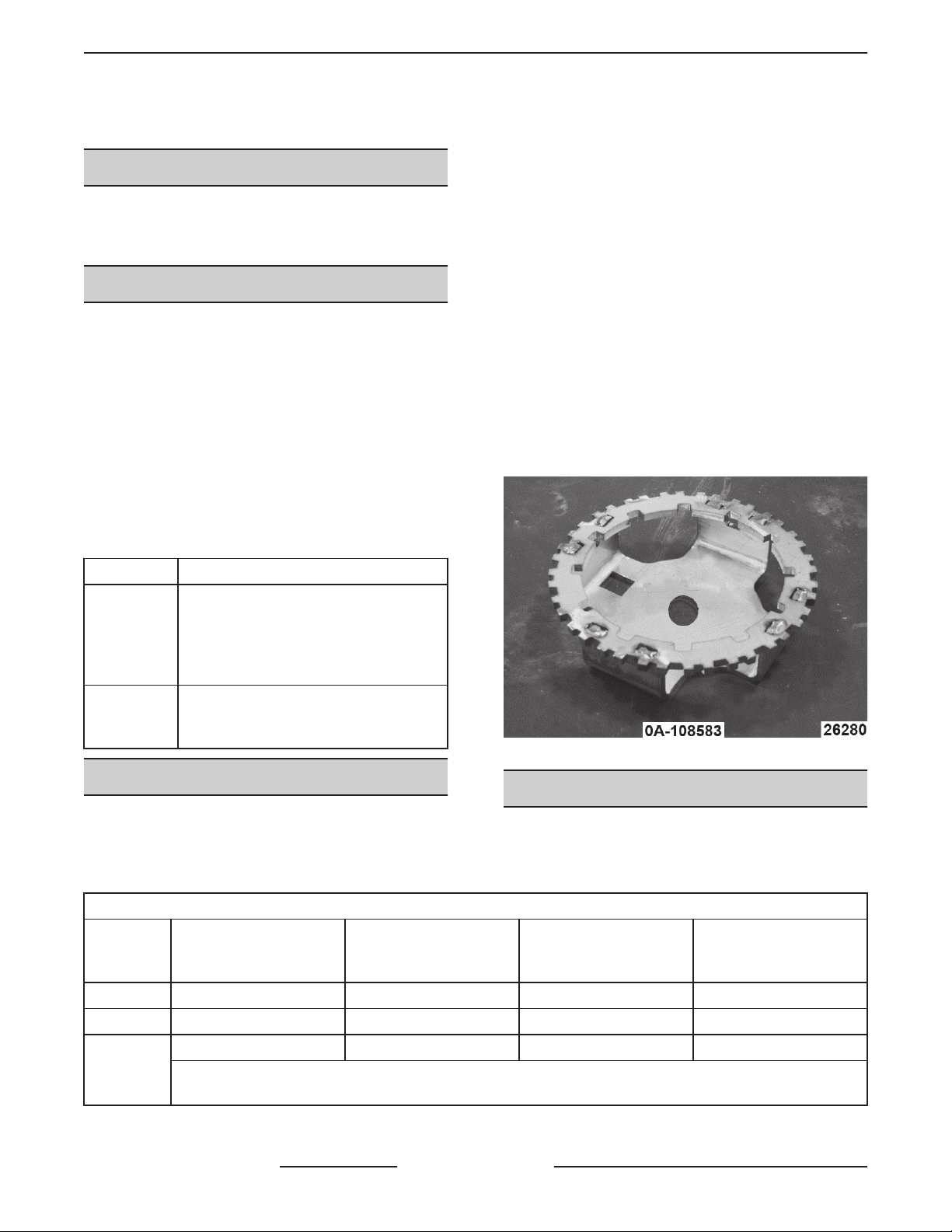
CHEMICAL PUMPS - WELCO
If chemical pump label is no longer visible, replace
label to identify pump for future servicing.
Disconnect the
electrical power to the machine and
follow lockout / tagout procedures.
Fig. 15
NUMBER DESCRIPTION
1Chemical Pump Motor
2Detergent Chemical Pump
3Rinse Aid Chemical Pump
4Chemical Sensor
5Sanitizing Chemical Pump (SU-L & SG
only)
1. Remove front trim panel.
2. Remove clamps and tube and pull from sensor.
3. Remove snap cover.
4. Remove tube from chemical sensor [5].
5. Replace with new chemical sensor [5].
6. Replace snap cover.
7. Replace hose to tube and sensor. Secure with
clamps.
NOTE: Do NOT use zip ties.
NOTE: Do NOT over squeeze clamp. Over squeezing
causes leaks.
Replacing Chemical Pump
1. Twist pump Counter Clock Wise and slide off
shaft.
2. Reverse procedure to install.
DRAIN PUMP
Disconnect the
electrical power to the machine and
follow lockout / tagout procedures.
1. Remove front trim panel and LEFT AND RIGHT
TRIM PANELS.
2. Remove electrical connections noting their
location.
Fig. 16
3. From left side using a long flathead screwdriver,
GENTLY open tab securing drain pump.
NOTE: Tab is easily broken. Do not need to replace
broken tab.
SG, SU-L, SU-H DISHWASHERS - REMOVAL AND REPLACEMENT OF PARTS
F45577 (1215) Page 10 of 59
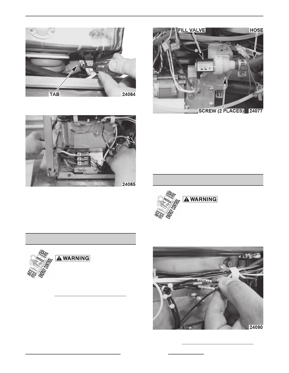
Fig. 17
4. Twist drain pump clockwise (CW) to remove.
Fig. 18
5. Reverse procedure to install.
NOTE: If tab on wash manifold is broken during drain
pump replacement, DO NOT replace wash manifold.
Drain pump can still be mounted securely without tab.
6. Check for proper operation.
FILL VALVE (1SOL)
Disconnect the
electrical power to the machine and
follow lockout / tagout procedures.
1. Shut off water supply.
2. Remove LEFT AND RIGHT TRIM PANELS.
3. Disconnect and drain water hose.
Fig. 19
4. Disconnect electrical connections from valve.
5. Remove mounting bracket screws.
6. Remove fill valve from bracket.
7. Disconnect and drain braided water line.
8. Reverse procedure to install.
9. Check for proper operation.
RINSE PUMP
Disconnect the
electrical power to the machine and
follow lockout / tagout procedures.
1. Remove front trim panel.
2. Disconnect rinse motor connections, 2MTR-1,
2MTR-2 and Ground.
Fig. 20
3. Remove LEFT AND RIGHT TRIM PANELS.
SG, SU-L, SU-H DISHWASHERS - REMOVAL AND REPLACEMENT OF PARTS
Page 11 of 59 F45577 (1215)

4. Remove fill valve (1SOL) from rinse pump.
NOTE: Leave electrical connections and hoses
connected to fill valve. Fill valve will be transferred to
replacement rinse pump.
Fig. 21
5. Disconnect inlet and outlet hoses from rinse
pump.
6. Remove 2 nuts securing rinse pump to base of
unit.
Fig. 22
7. Slide mounting bracket out from underneath clip
on base of unit, and remove rinse pump.
8. Transfer mounting bracket and fill valve to
replacement rinse pump.
9. Reverse procedure to install.
10. Check for proper operation.
RINSE PROBE (2QTM)
Disconnect the
electrical power to the machine and
follow lockout / tagout procedures.
1. Remove LEFT AND RIGHT TRIM PANELS.
2. Disconnect 2QTM at harness.
Fig. 23
3. Remove rinse probe from rinse tee.
Fig. 24
4. Reverse procedure to install.
NOTE: Use tape or thread compound to help seal
threads.
5. Check for proper operation.
SG, SU-L, SU-H DISHWASHERS - REMOVAL AND REPLACEMENT OF PARTS
F45577 (1215) Page 12 of 59
WASH PIPE ASSEMBLY
Disconnect the
electrical power to the machine and
follow lockout / tagout procedures.
1. Remove rinse pump and chemical pump bracket.
2. Remove WASH PUMP/MOTOR (1MTR).
3. Remove upper and lower wash and rinse arms.
4. Remove screw and retainer (top and bottom).
NOTE: Be careful to not drop screw or retainer into
wash pipe.
NOTE: Ensure retainer is off by removing wash
pipe.
Fig. 25
NOTE: Ensure retainer is off before removing
wash pipe.
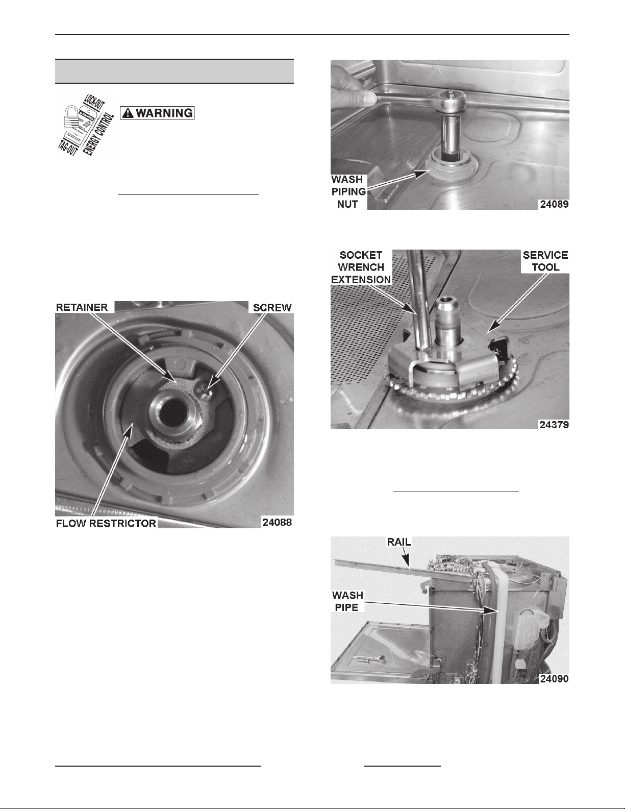
5. Remove spindle using 13/16" deep well socket.
6. Remove flow restrictor (lower manifold only).
Fig. 26
7. Remove wash piping nut using service tool.
Fig. 27
8. Disconnect any wiring that impedes wash pipe
assembly removal.
9. Remove CONTROL PANEL COVER.
10. Remove rear nut of rail.
11. Loosen front nut and rotate rail.
Fig. 28
12. Disconnect and note location of all electrical
connections to wash pipe assembly as
necessary.
SG, SU-L, SU-H DISHWASHERS - REMOVAL AND REPLACEMENT OF PARTS
Page 13 of 59 F45577 (1215)

13. Remove wash pipe assembly.
NOTE: If any tubes or wiring are routed between
wash pipe and rinse hose, disconnect rinse hose at
rinse tee to free tubes/wiring.
14. Transfer rinse hosing to replacement wash pipe.
15. Replace wash pipe O-rings.
16. Reverse procedure to install.
17. Check for proper operation.
WASH PUMP/MOTOR (1MTR)
Disconnect the
electrical power to the machine and
follow lockout / tagout procedures.
1. Remove front and right trim panels.
2. PURGE BOOSTER/HOLDING TANK FOR
SERVICE
3. Remove RINSE PUMP with fill valve (1SOL)
attached for a path to remove wash pump/motor
assembly.
NOTE: Stainless steel fill valve intake hose can
remain connected, but slack will need to be fed
through back of machine to clear assembly out of the
way.
Fig. 29
4. Remove any chemical tubing blocking removal
through the right side.
5. Disconnect pump manifold hose.
Fig. 30
6. Remove locator nut and rubber motor mount.
Fig. 31
7. From front of machine, unhook drain hose to
pump manifold and disconnect 1MTR
connections.
Fig. 32
8. Remove DRAIN PUMP.
9. Open door and remove strainers.
SG, SU-L, SU-H DISHWASHERS - REMOVAL AND REPLACEMENT OF PARTS
F45577 (1215) Page 14 of 59

10. Using service tool, remove pump nut.
NOTE: ⅜" drive extension can be used to turn service
tool.
Fig. 33
11. If clearance is necessary to remove wash pump/
motor, move chemical pump mounting bracket
assembly.
Fig. 34
12. Remove wash pump and motor assembly.
13. Reverse procedure to install.
NOTE: Transfer motor mount with locator nut just
started on threads onto replacement wash pump/
motor assembly.
NOTE: Once wash pump and motor are positioned
under dishwasher with motor mount slid into place,
tighten pump nut inside sump one thread for stability.
Once hose and electrical connections have been
made, tighten pump nut.
14. Check for proper operation.
BOOSTER HEATER (SU-H)
Disconnect the
electrical power to the machine and
follow lockout / tagout procedures.
1. Remove front trim and right side panel.
2. PURGE BOOSTER/HOLDING TANK FOR
SERVICE.
3. Disconnect booster heater wires from contactor.
4. Remove mounting screws.
Fig. 35
NOTE: Proper position with element wires on bottom.
5. Remove booster heater.
6. Reverse procedure to install.
7. Check for proper operation.
BOOSTER THERMISTOR & HIGH
LIMIT PROTECTION (SU-H)
Disconnect the
electrical power to the machine and
follow lockout / tagout procedures.
NOTE: Before replacing the High Limit, push reset
button on face of both high limit protectors. Verify that
this does not fix issue before proceeding.
Surface-Mount Thermistor
1. Remove front, left, and right trim panels.
2. Remove mounting nut and disconnect wires at
connector.
SG, SU-L, SU-H DISHWASHERS - REMOVAL AND REPLACEMENT OF PARTS
Page 15 of 59 F45577 (1215)

NOTE: When installing thermistor, verify there is
thermal paste on the side of the thermistor that is
mounted to the booster. Mount tightly to booster
surface and in same position as from the factory.
Thermal paste can be purchased at local store.
Fig. 36
3. Reverse procedure to install.
4. Check for proper operation.
High Limit Protectors
1. Remove front, left, and right trim panels.
2. Remove 2 screws and position FILL VALVE
(1SOL) out of the way.
3. Remove mounting bracket for 3TAS / 4TAS high
limit protectors.
Fig. 37
4. Remove high limit protector.
5. Reverse procedure to install.
6. Check for proper operation.
SUMP THERMISTOR & HIGH LIMIT
PROTECTION
NOTE: Before replacing the High Limit, push reset
button on face of both high limit protectors. Verify that
this does not fix issue before proceeding.
1. Drain the sump.
2. Remove LEFT SIDE PANEL.
3. For Surface Mounted Thermistor, remove
mounting nut and disconnect lead wires at
connector.
NOTE: When installing thermistor, mount tightly to
booster surface and in same position as from the
factory.
4. For High Limit Protectors, remove electrical
connections at high limits [1] and heater element.
Fig. 38
5. Remove sump heater mounting nuts [2].
6. Remove high limit protector mounting bracket.
7. Remove high limit protector.
8. Reverse procedure to install.
9. Check for proper operation.
AIR GAP
Disconnect the
electrical power to the machine and
follow lockout / tagout procedures.
1. Remove right side panel.
2. Remove air gap mounting screw.
SG, SU-L, SU-H DISHWASHERS - REMOVAL AND REPLACEMENT OF PARTS
F45577 (1215) Page 16 of 59
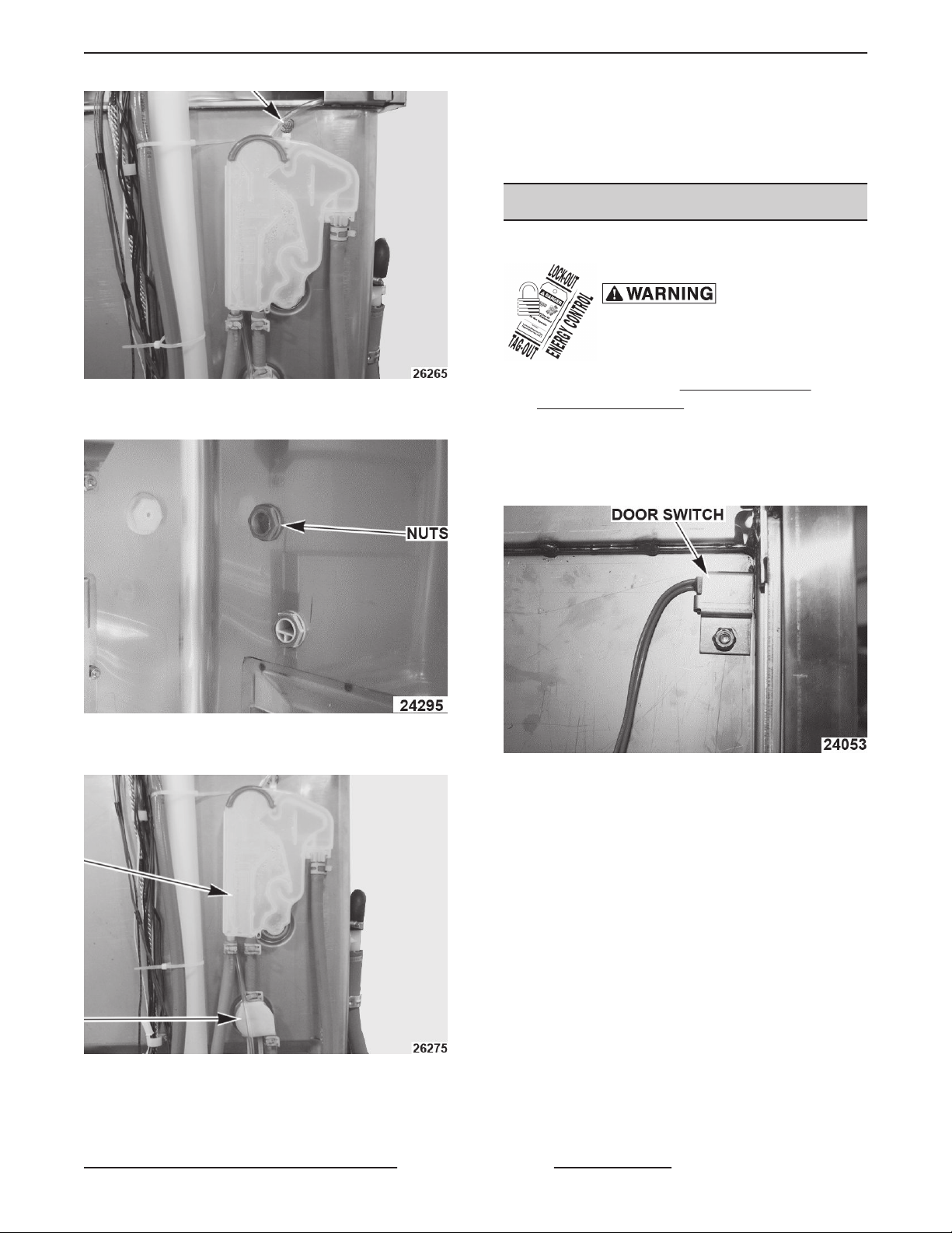
Fig. 39
3. Remove nuts from inside washer.
Fig. 40
4. Remove air gap.
Fig. 41
5. Disconnect hoses.
6. Reverse procedure to install.
NOTE: Make sure gasket is installed between inside
wall of tank and air gap. Replace gaskets as
necessary.
7. Check for proper operation.
DOOR SWITCH
NOTE: Door magnet is part of door.
Disconnect the
electrical power to the machine and
follow lockout / tagout procedures.
1. Place dishwasher in CONTROL PANEL
SERVICE POSITION.
2. Remove left side panel.
3. Disconnect door switch from control board (J10).
4. Remove screw securing door switch.
Fig. 42
NOTE: Door switch magnet is located inside the door
and is not serviceable.
5. Reverse procedure to install.
NOTE: Add small amount of Permagum between
sensor and bracket.
NOTE: Verify sensor is not lose and rattling.
6. Check for proper operation.
7. Check for rattles.
SG, SU-L, SU-H DISHWASHERS - REMOVAL AND REPLACEMENT OF PARTS
Page 17 of 59 F45577 (1215)

SERVICE PROCEDURES AND ADJUSTMENTS
REPLACEMENT CONTROL BOARD
PROGRAMMING
Certain procedures in
this section require electrical test or
measurements while power is applied
to the machine. Exercise extreme
caution at all times and follow Arc Flash
procedures. If test points are not easily
accessible, disconnect power and
follow Lockout/Tagout procedures,
attach test equipment and reapply
power to test.
Certain components in this system are
subject to damage by electrostatic discharge during
field repairs. A field service grounding kit is required
to prevent damage. The field service kit must be used
anytime the control board is handled.
NOTE: The replacement control board comes
programmed as an SG, SU-L, and SU-H or other OEM
machines must be reprogrammed to Stero.
Prior to removing board from machine, check and note
the settings of programmable variables as outlined
under SERVICE PROGRAMMING (8934) when
possible. When unable to access SERVICE
PROGRAMMING, check with establishment manager
to determine customer control settings. If control
settings cannot be determined, program according to
machine type SG, SU-L, and SU-H.
1. Press MENU button on keypad.
NOTE: Menu can also be accessed by shorting J27
(SVC) pins on control board. See CONTROL PANEL
SERVICE POSITION.
2. Enter SERVICE MENU.
3. Enter Service code 8934.
4. Select Edit Parameters, then Models.
5. Pick model based on data plate on door.
6. Select Exit Menu.
7. Shut down and cycle power to the dishwasher.
(Reboot)
8. Once power is reapplied turn machine on and re-
enter service programming to verify replacement
board is still set for the appropriate model.
9. Program replacement board to customer's
specifications using SERVICE PROGRAMMING
(8934).
10. Check for proper operation.
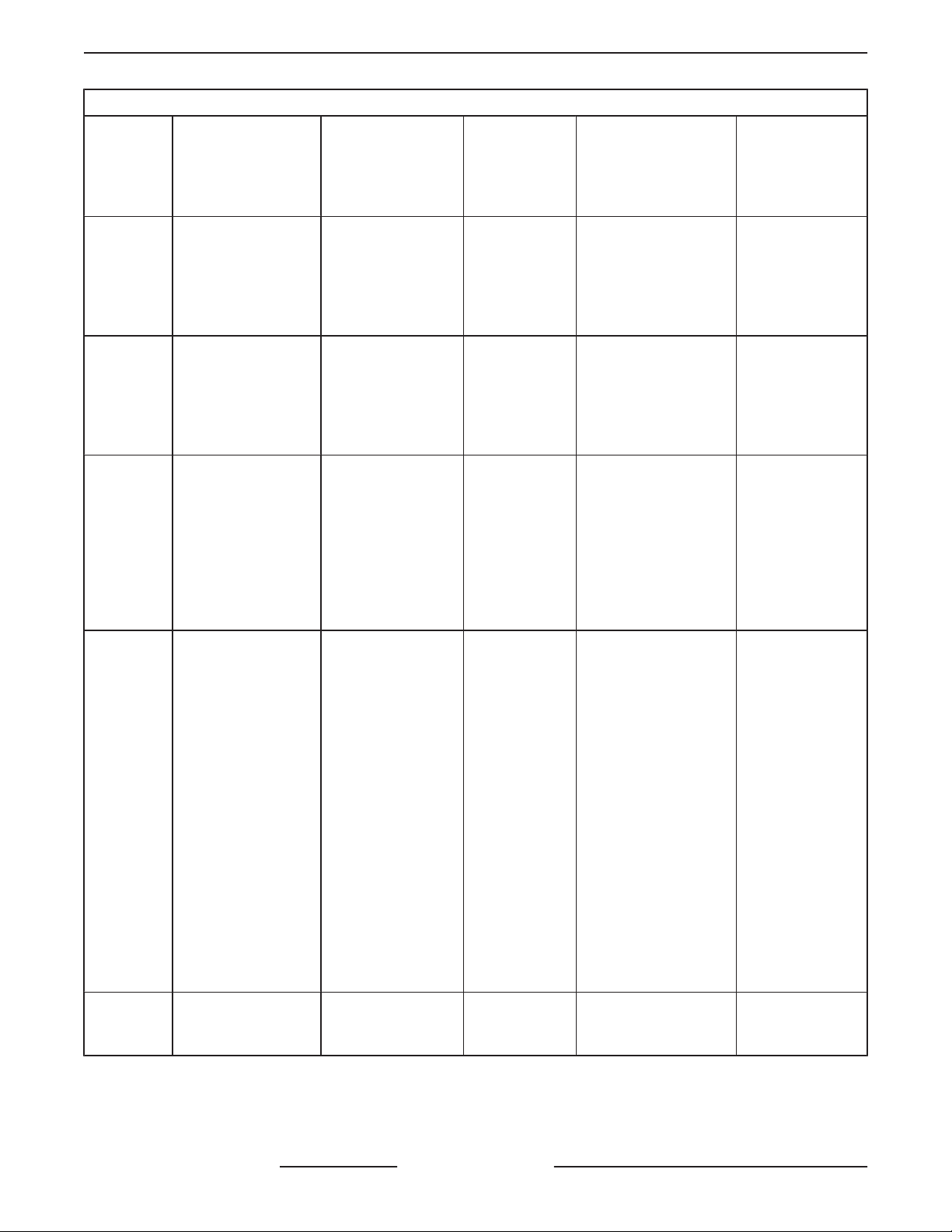
SERVICE PROGRAMMING (8934)
Service Programming
•EDIT PARAMETERS
•VIEW ERROR LOG
•VIEW STATS
•TOGGLE DIAGNOSTICS
•PRIME PUMPS
•IMMEDIATE SHUTDOWN
•SHOW SOFTWARE REVISION
•RESET PARAMETERS
•EXIT MENU
1. Press MENU button on keypad.
2. Enter SERVICE MENU.
3. Enter Service code 8934.
EDIT PARAMETERS
Parameter
Name
Cold Units
(Stero Cold SU-L)
(Glass Washer:
Stero Cold SG)
Hot Units
(Stero Hot SU-H) Description Possible Values Default Values
Model Stero Cold SU-L
Stero Cold SG Stero Hot SU-H
Select
programming
for appropriate
model of
dishwasher.
Stero Hot SU-H
Stero Cold SU-L
Stero Cold SG
LXeH Base Hot
SG, SU-L, SU-H DISHWASHERS - SERVICE PROCEDURES AND ADJUSTMENTS
F45577 (1215) Page 18 of 59

EDIT PARAMETERS
Parameter
Name
Cold Units
(Stero Cold SU-L)
(Glass Washer:
Stero Cold SG)
Hot Units
(Stero Hot SU-H) Description Possible Values Default Values
Booster
Temp Set
Pt.
N/A Stero Hot SU-H
Booster
temperature
set point.
FSP -12 to FSP +12 FSP 0
Sump
Temp Set
PT.
Stero Cold SU-L
Stero Cold SG Stero Hot SU-H
Sump
temperature
set point.
120-170°F/49-77°C
130°F / 54°C
(Stero SU-L &
SG)
165°F / 77°C
(Stero SU-H units
only)
Detergent
Pump
Stero Cold SU-L
Stero Cold SG Stero Hot SU-H Detergent
pump option. Disabled / Enabled Enabled
Detergent
Flow Rate
Stero Cold SU-L
Stero Cold SG Stero Hot SU-H
Detergent flow
rate measured
in mL per cycle.
OFF through 20.0 mL 7.9 mL
Rinse Aid
Pump
Stero Cold SU-L
Stero Cold SG Stero Hot SU-H
Rinse Aid
pump
operation.
Disabled / Enabled Enabled
Rinse Aid
Flow Rate
Stero Cold SU-L
Stero Cold SG Stero Hot SU-H
Rinse aid flow
rate measured
in mL per cycle.
OFF through 8.8 mL 1.8 mL
Sanitizer
Flow Rate
Stero Cold SU-L
Stero Cold SG N/A
Sanitizer flow
rate measured
in mL per cycle.
Off to 100 mL 60 mL
Detergent
PWM Freq
Stero Cold SU-L
Stero Cold SG Stero Hot SU-H
DO NOT
ADJUST.
Contact Stero
technical
support.
5000-50,000 (by
1000's) 10,000
Rinse Aid
PWM Freq
Stero Cold SU-L
Stero Cold SG Stero Hot SU-H
DO NOT
ADJUST.
Contact Stero
technical
support.
5000-50,000 (by
1000's) 10,000
Sanitizer
PWM Freq
Stero Cold SU-L
Stero Cold SG N/A
DO NOT
ADJUST.
Contact Stero
technical
support.
5000-50,000 (by
1000's) 10,000
Detergent
Threshold
Stero Cold SU-L
Stero Cold SG Stero Hot SU-H
Sets maximum
allowable
chemical
sense reading
(mV) for
detergent.
0-4000 (by 100's) 1100
SG, SU-L, SU-H DISHWASHERS - SERVICE PROCEDURES AND ADJUSTMENTS
Page 19 of 59 F45577 (1215)
EDIT PARAMETERS
Parameter
Name
Cold Units
(Stero Cold SU-L)
(Glass Washer:
Stero Cold SG)
Hot Units
(Stero Hot SU-H) Description Possible Values Default Values
Rinse Aid
Threshold
Stero Cold SU-L
Stero Cold SG Stero Hot SU-H
Sets maximum
allowable
chemical
sense reading
(mV) for rinse
aid.
0-4000 (by 100's) 2500
Sanitizer
Threshold
Stero Cold SU-L
Stero Cold SG N/A
Sets maximum
allowable
chemical
sense reading
(mV) for
sanitizer.
500-4000 (by 100's) 1100
Rinse
Assurance N/A Stero Hot SU-H
Lengthens
wash time, if
necessary, to
allow booster
to heat
incoming
110°F water to
180°F. Time
may vary.
Disabled / Enabled Enabled
Soft Start
Period
Stero Cold SU-L
Stero Cold SG Stero Hot SU-H
Reduces
voltage and
current to wash
pump at
beginning of
wash cycle for
5-6 seconds.
Lower is not
softer and
higher is not
harder. If
unsure how to
adjust, call
Stero technical
support.
1.67 ms
2.09 ms
2.50 ms
2.92 ms
3.34 ms
3.75 ms
4.17 ms
4.59 ms
5.00 ms
5.42 ms
5.84 ms
6.26 ms
6.67 ms
4.17 ms
Exit Menu Stero Cold SU-L
Stero Cold SG Stero Hot SU-H
Exits
Parameter
Menu.
SG, SU-L, SU-H DISHWASHERS - SERVICE PROCEDURES AND ADJUSTMENTS
F45577 (1215) Page 20 of 59
This manual suits for next models
2
Table of contents
Other STERO Dishwasher manuals


